The joint operation of a motion sensor and a lamp increases the level of comfort in a home, apartment and even office. The lighting turns on automatically when a person enters the room. When the room is empty, the light automatically goes out, which is an additional energy saving. To connect a motion sensor to a light bulb, the article presents installation diagrams, basic connection rules and operating principles that even novice electricians can understand.
Main functions and operating principle
The motion sensor is designed to detect a moving object and send a corresponding signal to the control body through switching the electrical circuit. Works with active and active-inductive loads in the circuit.
If movement is detected in the controlled area, the light detection process chain starts (if the sensor supports this function). When readings are below the set response threshold, the contacts close, current is supplied to the lamp and the lamp lights up.
According to this principle, the sensor is ready to work in the dark and during daylight hours. The response threshold is set by regulators in the range of 3-2000 Lux.
But a motion sensor can work on a different principle: capturing electromagnetic oscillations of waves in the infrared spectrum. At the same time, sensors often have an adjustable delay to turn on when motion is detected
The shutter speed mode is set by turning the knob. In this case, the delay for operation can be different for everyone: from 10 seconds to 15 minutes.
At the same time, there is no need to buy a finished product in the form of a lamp with a sensor. It is enough to purchase a sensor suitable for this role and include it in the electrical circuit.
Configuring and adjusting device settings
In order for the device to correctly respond to movement and not react to interference, the movement of pets or branches outside the window, it is important not only to install it correctly, but also to configure it correctly.
Viewing angle
Some devices allow you to control the viewing angle using a special switch on the device body. This makes it possible to reduce or, conversely, increase the angle of the controlled zone by the motion sensor for correct operation. Those devices that do not have viewing angle adjustment can be adjusted by turning them in the desired direction or using a wall as a limiter. Craftsmen also resort to using electrical tape, artificially limiting the sensor’s view by taping its scanning screen in the right places.
Sensitivity (SENS)
This switch allows you to reduce the number of false alarms from pets, tree branches outside the window and other factors. Adjustment for this factor begins with the minimum value of the switch, followed by an increase to the desired value. All this is done experimentally with mandatory testing.
Shutdown delay (TIME)
The ability to configure the delay depends on the specific device and can range from 5 seconds to 30 minutes. This parameter is adjusted based on user preferences and the purpose of the room or lighting. It works as follows: when motion is detected, the lighting turns on and then turns off only after the configured delay on the device has expired.
Light level (LUX/DAY LIGHT)
Setting this parameter is made to adjust the switching on of the lighting device at a given illumination. That is, it will turn on only if movement is detected at the adjusted light level. If the illumination in the room is higher, the device will not turn on. The adjustment is made from the minimum value, gradually increasing to the required value.
Two-wire connection of a motion sensor
Regardless of the design, motion sensors are divided into two-wire and three-wire based on the connection method.
By design, two-wire ones are usually placed in socket boxes. Basic elements for connection:
- Automatic switch for electrical appliances from a 220V network (usually located in the distribution panel).
- Junction box (usually recessed into the wall/ceiling).
- Motion Sensor.
- Lamp.
The sensor connection is the same as for a single-key switch for artificial lighting. That is, the phase through which the current will flow must be brought to the sensor, and passed through it further to the lamp. In this case, it is recommended to install it on a separate circuit and install it on general lighting.
Installation
The installation process goes like this:
- Lead the three-core cable VVGng-Ls 3*1.5 mm2 from the circuit breaker panel into the distribution box. Mark the conductors for convenience: L (phase), N (working zero), protective zero or ground (PE).
- Lead the two-core wire (extension cord) from the other side into the junction box, first connecting it to the sensor on the other side through the terminal blocks.
- It is recommended to place the motion sensor (if it is a socket box) at a level of 1.2 - 2 meters from the floor level.
- Such sensors should not be confused with wall sensors, which are placed at the entrance, in corridors or in the entrances of a multi-story building. Those used for lighting are usually installed under the ceiling near the doors.
- The viewing level should not be blocked by moving objects (open doors or curtains).
- Also lead the cable from the lamp into the distribution box. First connect the power supply + lamp. Then ground the first and second cable together.
- Connect phase (L) from the circuit breaker to the first core. Connect the second wire to phase (L) of the lamp. For high-quality and aesthetic connections, it is recommended to use Wago terminals.
- The sensor is connected in the socket box according to the following diagram: the first wire (which comes from the machine) is connected to the socket marked (L).
- The second core is inserted into the socket marked “load”.
- Hide the connected sensor in the socket box and put on the structure housing.
Settings
The electrical connection is complete. Now you should configure the sensor on the front panel:
- Turn the first knob to set it to auto mode.
- The second regulator is responsible for sensitivity to light. To activate the sensor only in the dark, turn the control the required number of degrees to the left.
- Timer to turn off lighting when there is no movement in the controlled area. The time range is usually indicated in the device characteristics in the operating instructions.
Ready. At the switchboard, turn the circuit breaker to the "on" position and check the work you just did.
Advantages
Among the positive aspects of this scheme are:
- Easy installation and step-by-step configuration;
- Versatility;
- Automatic switching on of light without installing additional switches;
- Interchangeability with single-key switch.
Flaws
A significant disadvantage of a two-wire sensor is poor interaction with LED and energy-saving lamps. The latter can flicker quite strongly, which, in addition to discomfort, increases the possibility of rapid burnout.
Connection features
If you are planning to install a motion sensor with your own hands, then your toolkit must have a voltage indicator. In principle, this is a common rule for all professional electricians. But if a mechanical switch can still be installed in the neutral gap without catastrophic consequences, then it is absolutely impossible to supply a phase to the N terminal of the device, this will cause its failure.
The device will not work until voltage appears at the L terminal - its signal circuit will not be energized and will remain “dead”. This property is used when connecting in series.
The rated power of the sensor must correspond to the power consumption of the controlled element. But it’s better if it is one and a half to two times more. Failure to comply with this condition will lead to mechanical melting of the power relay contacts or electrical breakdown of the semiconductor switch, after which the sensor will be easier to replace than to repair.
Knowing the principle, you can easily connect motion sensors in any combinations and combinations with other types of switching devices. Of course, all work must be carried out with the voltage completely removed and other electrical safety standards observed.
Three-wire motion sensor connection diagram
Three terminal sensors are typically used in IR sensor type designs. A fairly common manufacturer of inexpensive infrared motion sensors is IEK. You can find good products on Aliexpress without any problems.
More expensive products are made according to a similar principle; the connection diagram for a lamp with a sensor is similar for a sensor model from any manufacturer. Devices must have a degree of protection IP44 against penetration of solid objects greater than 1 mm and drops of moisture. If the motion sensor needs to be moved outside the house, then installation is only possible under a canopy.
If you want to protect the device from rain and snow, look for a model with IP65 dust and moisture protection and a temperature rating for your climate. Most IR sensors can only operate down to minus 20 degrees Celsius.
To connect a three-wire IR motion sensor, a full phase and zero are started. For correct placement you will need the same basic 4 elements:
- Circuit breaker (which is in the switchboard).
- Distribution box (in which the main installation).
- Sensor (a wire from the junction box is connected to it).
- Lamp (second wire from the junction box).
The sensor is connected with three wires to the factory in the distribution box of three cables:
- There are three wires from the machine: L (phase), N (working zero), protective zero or ground (PE).
- There are three wires per lamp if the body of the lighting fixture is made of metal.
- Three wires per sensor.
How to connect a motion sensor to a light bulb using three wires is discussed in detail in the diagram.
The zeros (N) are collected at one point (as in the case of the previous diagram). The ground from the circuit breaker is also connected to the luminaire ground (zero drive or PE). The motion sensor with three terminals is now supplied with phase-zero:
- Two input ones are for 220V power supply, usually labeled as L (phase) and N (zero).
- One output is designated by the letter A.
Installation
To install a three-wire motion sensor:
- Unscrew the two screws in the housing. The terminals are located under the back cover.
- Some models are already led out of the housing by three wires of different colors. By color you can determine what it means: ground (A) red, zero (N) blue, phase (L) brown. But if the cover opens without much effort, it is recommended to verify the correctness of certain markings in person by looking at the inscriptions next to the terminals.
- A simplified diagram of connecting a motion sensor to a light bulb looks like this:
- A little clarity in this picture.
- You can do without a junction box for connecting wires and run all the wires directly into the sensor box, if the inside is spacious enough and has its own terminal block. Phase-zero was supplied from one cable, and phase-zero was removed from the other.
- The result is a simplified, but the same three-wire circuit, only without a junction box.
Setting and adjusting sensitivity
After successfully connecting a lamp with a motion sensor, you need to set its parameters correctly:
- On the back of the case, find the main controls. LUX with the positions of the month and the sun is responsible for triggering depending on the illumination. Do you need the sensor to turn on in a room with a window only when it is cloudy or the sun goes down? Turn the regulator towards the moon.
- Use the second regulator to set the shutdown time. The delay can be set from a few seconds to 5-10 minutes.
- The rotation angle of the entire sphere allows you to adjust the detection of animals.
Advantages and nuances of use
To prevent the sensor from reacting to animals, do not turn the sensor head down towards the floor. Position it so that it captures the movements at the level of the head (shoulders) of all residents of the house. Typically, animal capture does not occur at this level.
If you need the sensor to temporarily not work, then point its head at the ceiling. Therefore, motion capture is not possible. The sensor's motion capture depends on the angle of inclination. In reality, the maximum distance reaches 9 meters. But according to the passport it may be higher.
The sensor uses infrared rays for detection. If you move from beam to beam, the device notices activity and reacts. When you walk directly into the beam, the sensitivity of the sensor is minimal and the device may not immediately respond to you.
For this reason, motion sensors are installed not directly above the doorway, but slightly to the side. For example, in the corner of the room.
Flaws
The disadvantage of the three-wire circuit for connecting the motion sensor to the lamp is that the light does not turn on forcibly. If the sensor malfunctions for some reason, problems will begin with its correct operation. To avoid this, it is recommended to add a switch to the circuit.
Types and varieties
Motion sensors for turning on lights can be of different types, designed for different operating conditions. First of all, you need to look at where the device can be installed.
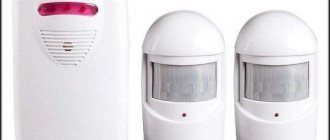
A motion sensor to turn on the lights is needed not only on the street
Outdoor motion sensors have a high degree of housing protection. For normal use outdoors, take sensors with an IP of at least 55, but better - higher. For installation in a home, you can take IP 22 and higher.
Power type
Next, you need to consider what source the light sensor is powered from. There are the following options:
- Wired sensors powered by 220 V.
- Wireless, powered by batteries or rechargeable batteries.
Motion sensors are wired and wireless
The largest group is wired for connecting to 220 V. There are fewer wireless ones, but there are also enough of them. They are good if you need to turn on lighting powered by low-voltage power sources - rechargeable batteries or solar panels, for example.
Method for determining the presence of motion
The motion sensor for turning on the light can detect moving objects using various detection principles:
- Infrared motion sensors. They react to the heat generated by the body of warm-blooded creatures. They are classified as passive devices, since they themselves do not produce anything, they only register radiation. These sensors also react to the movement of animals, so there may be false alarms.
- Acoustic motion (noise) sensors. Also belongs to the passive group of equipment. They react to noise and can be turned on by a clap or the sound of a door opening. They can be used in the basements of private houses, where noise occurs as soon as someone enters there. Use elsewhere is limited.
The operation of infrared motion sensors is based on tracking the heat generated by a person - Microwave motion sensors. Belong to the group of active devices. They themselves produce waves in the microwave range and monitor their return. In the presence of a moving object, contacts are closed/opened (there are different types). There are sensitive models that “see” even through partitions or walls. Typically used in security systems.
- Ultrasonic. The principle of operation is the same as that of microwaves, but the range of emitted waves is different. This type of device is rarely used, since animals can react to ultrasound, and long-term exposure to humans (the devices constantly generate radiation) will not bring any benefit.
Various designs, but the color is mainly white and black - Combined (dual). Combines several motion detection methods. They are more reliable, have fewer false positives, but are also more expensive.
Most often, infrared motion sensors are used to turn on lights on the street or at home. They have a low price, a large range of action, and a large number of adjustments that will help you customize it. On stairs and in long corridors it is better to install a sensor with ultrasound or microwave. They are able to turn on the lighting even if you are still far from the light source. Microwaves are recommended for installation in security systems - they detect movement even behind partitions.
Scheme for connecting a motion sensor with a switch
This circuit is considered universal, because it uses a single-key switch.
Since the switch has two wires, and the sensor has three, there is a great way for this - parallel connection:
- Connect the phase from the automatic power supply simultaneously to the switch and the sensor (Wago terminals help).
- Connect the second wire from the one-key switch to the output wire from the sensor (again using Wago terminals).
This circuit will allow you to turn the lighting in the room on and off, regardless of the operation of the motion sensor. Even if it breaks down temporarily, you will not be left without lighting at the right time.
The serial connection (a phase break occurs before the sensor) in this circuit has a significant flaw - completely de-energizing the motion sensor resets its original settings, to which it returns within 20 seconds. Imagine a situation where you turn on the light, stand in the dark, wave your hands in front of the sensor, but it does not react in any way to these movements. The comfort of such a gadget disappears instantly.
Video description
The video shows how to connect a motion sensor:
Connection diagram with switch
It should be noted right away that the motion sensor and the switch in the circuit are connected in parallel to each other. Therefore, in addition to the fact that all wires, namely ground and zero, are connected in exactly the same way as in the previous case, the connection of phase conductors is carried out like this:
- the wire from the machine is connected to the incoming core of the sensor;
- the same wire from the machine is connected to the switch;
- the output wire from the motion device is connected to the lamp;
- A wire is laid from it to the switch.
This circuit will allow you to turn on the lighting using a switch, regardless of the time of day, and also regardless of whether the motion sensor is working or is broken.
Connection diagram of a sensor with a switch Source elektromontagy.ru
Connecting a three-wire sensor to two wires
A fairly common question is: can a three-wire sensor be connected not in parallel with a switch, but instead of a single-key switch. Essentially, remove it from the circuit and allow it to break into phases, as in the case of a two-wire circuit.
Theoretically, this trick can actually work with some lamps. But for this you will need additionally:
- Diode VDI 1N4007;
- Capacitor 2.2 MKF at 400V.
The diode must be installed between the two terminals A-output from the sensor and where zero N is connected. The capacitor itself must be soldered parallel to the light bulb in the lamp. According to the diagram, it turns out that one phase arrives at the sensor, enters contact L and leaves contact N. Output A apparently remains unconnected.
The scheme is popular among residents of houses where a two-core power cable is laid and they do not want to change anything in this direction.
Flaws
The disadvantages are the following:
- Doesn't work with all LED bulbs.
- The pulsation can be so high that it causes enough discomfort, creating additional strain on the eyes.
- You cannot add any other load to the circuit, because nothing else will work here.
- The maximum power of this lighting is 80W.
The light sensor works in reverse
And if for some needs you need the relay to operate in reverse mode? It supplied voltage and turned on the load during the day and turned it off at night.
For example, for lighting in a barn with animals where there are no windows. What to do in this case?
Then go to the nearest store and buy an intermediate relay, in which one of the contacts closes and the other opens when triggered.
All you need to do is connect this intermediate relay after the light sensor according to the diagram below.
A starter with additional contacts can also act as such a relay.
Circuit with two sensors
If you need to illuminate a long, L-shaped or other type of room, you will need to install several sensors to capture motion. To avoid using extra meters of cables, connect both devices in parallel.
In this scheme, the number of connected sensors is not limited.
It works according to this principle:
- We stepped onto the threshold of a long corridor with a corner turn and the light automatically came on.
- We reached the activation zone of the second sensor - the lighting did not stop.
- Turned 90 degrees and your movement was caught by the third sensor. The coverage is still ongoing.
- After leaving the corridor completely, the lighting stops.
Recommendations for choosing an installation location
Sensors can be installed inside the house or outside.
Street sensors monitor the area adjacent to a particular building. The perception range of these devices is usually large. For some devices it reaches hundreds of meters. But such indicators are not particularly suitable for the courtyard of a private house.
When returning home or going out in the dark, the devices will be especially convenient for the owners. The LUX button helps with settings.
Internal sensors work indoors. Differences from other types lie in the following properties:
- Poor protection from atmospheric influences.
- Smaller field of view. If there is no movement, work stops.
- Reduced cost.
Circuit with starter or contactor
The previous connection diagrams are designed for loads within one kilowatt. But there is an alternative type of lighting with powerful loads, for example, sodium arc tube lamps. Or a large load is required to run the fans in the hood along with the lighting.
In this case, a circuit with a starter is used (the load passes through the contacts of the starter). And Sensor-IR in this circuit controls the contactor coil.
The energized output contact from the sensor will energize the coil. Zeros are combined into one common one.
Common errors during installation
The most common mistakes made when installing a motion sensor are:
- lighting equipment is located next to the motion sensor, leading to malfunctions;
- the viewing angle does not cover part of the territory, which is why the light turns on only once;
- a heater or air conditioner is located in the control zone, the air flows of which affect correct operation;
- There is a bulky object in front of the sensor, which significantly narrows the viewing angle.
Operational problems or connection errors
Problems with motion sensors include:
- Connecting phase and neutral. According to the operating logic of the device, it does not matter where the zero and phase are connected. But for safety reasons, the break should be located precisely on the conductor connected to the phase. An analogy for such inclusion can be given with a lamp socket.
- False positives. Possible if the sensors are positioned incorrectly, installation near warm or heating elements, installation outdoors, near tree leaves or other extraneous factors.
- Unreasonable activation immediately after deactivation. If a lamp or other light-emitting device is directed at the photorelay of the sensor, this will cause this behavior of the device. A nearby lamp with an incandescent lamp, which does not go out immediately when turned off. The sensor can detect IR waves and start the lighting activation chain. Cases of an endless cycle of activation by IR waves cannot be excluded.
- Mounting the motion sensor on the wall, although according to the passport it is ceiling mounted. It’s not for nothing that the technical specifications indicate the mounting option (wall/ceiling). This has to do with the design of the diagrams. Such devices have different viewing angles and, as a result, problems arise if installed incorrectly.
- Glare and air currents. Factors such as glare and strong air currents cause the IR sensor to react. If a similar situation with glare is discussed in the third paragraph, then with wind things are different. Installation directed towards windows, split systems, or outdoors where there is a strong draft is not recommended.
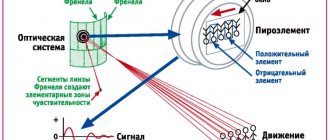
- Cracks or contamination on the sensitive element when connected to the spotlight. This element in the sensor is the Freckel lens. It is needed to focus IR radiation using concave segment mirrors located inside. If there is a lot of dirt or a crack appears in the front, this means that the device is not working properly.
Specifications
Once you have decided which motion sensor you will install to turn on the lights, you need to select its technical characteristics.
The technical characteristics of wireless models also include the frequency at which they operate and the type of batteries
Viewing angle
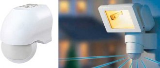
The motion sensor for turning on the light can have a different viewing angle in the horizontal plane - from 90° to 360°. If an object can be approached from any direction, sensors with a radius of 180-360° are installed, depending on its location. If the device is mounted on a wall, 180° is enough, if on a pole, 360° is already needed. Indoors, you can use those that track movement in a narrow sector.
Depending on the installation location and the required detection zone, select the viewing radius
If there is only one door (a utility room, for example), a narrowband sensor may be sufficient. If the room can be entered from two or three sides, the model should be able to see at least 180°, and better yet, in all directions. The wider the coverage, the better, but the cost of wide-angle models is much higher, so you should proceed from the principle of reasonable sufficiency.
There is also a vertical viewing angle. In ordinary inexpensive models it is 15-20°, but there are models that can cover up to 180°. Wide-angle motion detectors are usually installed in security systems, and not in lighting systems, since their cost is considerable. In this regard, it is worth choosing the correct height for installing the device: so that the “dead zone”, in which the detector simply does not see anything, is not in the place where the movement is most intense.
Range
Here again, you should choose taking into account whether a motion sensor will be installed indoors to turn on the lights or outdoors. For indoor environments, a range of 5-7 meters is sufficient.
Choose range with reserve
For the street, it is desirable to install more “long-range” ones. But look here too: with a large coverage radius, false positives can be very frequent. So having too much coverage can even be a disadvantage.
Power of connected luminaires
Each motion sensor for turning on the light is designed to connect a certain load - it can pass a current of a certain rating through itself. Therefore, when choosing, you need to know the total power of the lamps that the device will connect.
The power of the connected lamps is critical if a group of lamps or one powerful one is turned on
In order not to overpay for the increased capacity of the motion sensor, and even save on electricity bills, use not incandescent lamps, but more economical ones - gas discharge, fluorescent or LED.
Installation method and location
In addition to the obvious division into street and “home”, there is another type of division according to the location of installation of motion sensors:
- Case models. A small box that can be mounted on a bracket. The bracket can be fixed: on the ceiling;
- on the wall.
The type of motion sensor cannot be determined by its appearance, you can only understand whether it is installed on the ceiling or on the wall
If the lighting is turned on only to increase comfort, cabinet models are chosen, since they are cheaper with equal characteristics. Built-in ones are installed in security systems. They are miniature, but more expensive.
Additional functions
Some motion detectors have additional features. Some of them are obvious overkill, others, in certain situations, can be useful.
- Built-in light sensor. If a motion sensor to turn on the light is installed on the street or in a room with a window, there is no need to turn on the light during daylight hours - the illumination is sufficient. In this case, either a photo relay is built into the circuit, or a motion detector with a built-in photo relay is used (in one housing).
- Protection from animals. A useful feature if you have cats or dogs. With this function there are much fewer false positives. If the dog is large, even this option will not save you. But it works well with cats and small dogs.
For many, a useful feature would be protection against triggering when animals appear. - Light off delay. There are devices that turn off the light immediately after the object leaves the coverage area. In most cases this is inconvenient: light is still needed. That’s why models with a delay are convenient, and even more convenient are those that allow you to adjust this delay.
These are all features that may be useful. Pay special attention to animal protection and shutdown delay. These are really useful options.
Light sensor installation
It would seem, what is so wise here? I screwed it on (see the picture at the beginning of the article), connected it, configured it, and that’s it! But sometimes the installation location is chosen poorly, and problems begin.
On our street at one time the street lights turned on in an intricate way in the evening. They will turn on, go out, turn on again, and so on with a period of about 1 minute. Then, with the onset of good darkness, they turned on completely.
Why is that? The light sensor was simply mistakenly installed in the illumination zone of the flashlight being turned on. It turns out: it became dark - the sensor worked - the flashlight came on - it became light - the sensor turned off - it became dark... And so on, a vicious circle.
Installation.
There are many options for placing wall sensors, but the best option is in the corner of the room. This is also evidenced by the beam opening diagram in the figure above (top view). Look at my example. I have a sensor installed in the corner, and to the right of it, above the door, there is a lamp hanging.
From personal experience I will say that the sensor-lamp combination is best used separately from the existing lighting. To do this, draw a separate line in which only the sensor, lamp and switch will be involved. This way you can always turn off the motion sensor when it is not needed.
By the way, you can also use a working switch. For example, if you have a single one, then we change it to a double one, and use the free contact of the switch to supply 220V power to the sensor. If there is a double switch, then accordingly we change it to a triple one. I have it distributed like this:
Let's consider the option of installing a wall sensor in the hallway of an apartment.
As a rule, in our apartments, doors from all rooms lead to the hallway. Task
: where to install the sensor so that when leaving any room it turns on the light? Everything is very simple.
Knowing the diagram of the rays
wall sensor, choose the most optimal location for installation. For example:
In the figure, the controlled zone is indicated in yellow; when crossed, the sensor will trigger and the light will turn on. But there are also dead zones
where he can't see you. But these zones can be neglected, since when leaving any room, you still find yourself in a controlled zone.
Of course, the physics of the beam is difficult to predict, so the controlled area is shown approximately, but this is exactly how it will be distributed in the hallway with a deviation, plus or minus a few centimeters. Here is a real example corresponding to the picture above:
In any case, experiment. It is even possible to install a combined wall and ceiling sensor at the same time, where the operation of only one type will not be effective.
Pinout of PIR sensor HC-SR501
The HC-SR501 has a 3-pin connector that connects it to the outside world. The following contacts are displayed on it:
Figure 8 – Pinout of PIR sensor HC-SR501
VCC is the power pin for the HC-SR501 PIR sensor, to which we connect the 5V pin on the Arduino.
The output pin is a logic output with a TTL level of 3.3 V. A low logic level means that no motion is detected, a high logic level means that some motion has been detected.
GND should be connected to Arduino ground.
Things to Consider Before Designing PIR Sensor Applications
Like most PIR sensors, the HC-SR501 takes some time to adapt to the infrared energy in the room. This takes 30 to 60 seconds the first time you turn on the sensor.
Additionally, the sensor has a "reset" period of about 5 or 6 seconds after reading. During this time it will not detect any movement.
When designing a system based on the HC-SR501, you will need to take these delay times into account.
Original article:
- How HC-SR501 PIR Sensor Works & Interface It With Arduino
Features and application of radio wave monitoring equipment
Principle of operation
Radio wave sensors are based on the reflection of electromagnetic waves from an object.
- insensitivity to infrared radiation - heat, acoustic waves and small vibrations;
- radio transparency for walls and glass within the field of action.
- sensors with a 360° field of action are mounted centrally to the ceiling;
- with 180° field on the wall;
- at 90° or less in a corner or on a wall, depending on the direction towards the security object.
PIR motion detector HC-SR501
For most of our Arduino projects that need to detect when a person has left, entered, or approached an area, the HC-SR501 PIR sensors are an excellent choice. They have low power consumption and low cost, are quite durable, have a wide range of lenses, are easy to interact with, and are wildly popular among hobbyists.
The HC-SR501 PIR sensor has three pins: VCC power, output and ground (shown in the figure below). It has a built-in voltage regulator so it can be powered by any DC voltage from 4.5 to 12 volts, 5V is commonly used. In addition, it has several settings. Let's check them out.
Figure 4 – PIR sensor pinout. Arrangement of components on the board.
The board has two potentiometers for setting a couple of parameters:
- Sensitivity – Sets the maximum distance at which motion can be detected. It varies from 3 to 7 meters. The actual distance you get may be affected by the layout of your space.
- Time – Sets the time the output signal will remain high after detection. Minimum – 3 seconds, maximum – 300 seconds or 5 minutes.
Finally, there is a jumper on the board (on some models the jumper is not soldered). It has two configuration options:
- H – this is hold/repeat/restart. In this position, the HC-SR501 will continue to output logic high as long as it continues to detect motion.
Figure 5 – Operation of the HC-SR501 PIR sensor in restart mode - L – is intermittent or non-repeating/non-restarting. In this position, the output signal will remain at a logic high level for the time set by adjusting the TIME potentiometer.
Figure 6 – Operation of the HC-SR501 PIR sensor in non-restart mode