A motion sensor is most often used to turn on lights when you pass or are near them. With its help, you can save electricity and save yourself from having to flip the switch. This device is also used in alarm systems to detect unwanted intrusions. In addition, they can also be found on production lines, where they are needed to automatically perform any technological tasks. Motion sensors are sometimes called presence sensors.
Types of motion sensors
Motion sensors are distinguished by their operating principle; their operation, accuracy and features of use depend on this. Each of them has strengths and weaknesses. The final price of such a sensor also depends on the design and type of element used.
The motion sensor can be made in one housing or in different housings (the control unit is separate from the sensor).
Contact
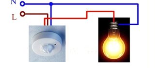
The simplest option for a motion sensor is to use a limit switch or reed switch. A reed switch (sealed contact) is a switch that is activated when a magnetic field appears. The essence of the work is to install a limit switch with normally open contacts or a reed switch on the door, when you open it and enter the room, the contacts will close, turn on the relay, and it will turn on the lighting. Such a diagram is shown below.
Infrared
They are triggered by thermal radiation and react to temperature changes. When you enter the field of view of such a sensor, it is triggered by thermal radiation from your body. The disadvantage of this detection method is false positives. Thermal radiation is inherent in everything that is around. Here are some examples:
1. An IR motion sensor is installed in a room with an electric heater, which periodically turns on and off using a timer or thermostat. When the heater is turned on, false alarms may occur. You can try to avoid this by taking a long time and carefully adjusting the sensitivity, as well as by trying to direct it so that there is no heater in the direct line of sight.
2. When installed outdoors, it may be triggered by gusts of warm wind.
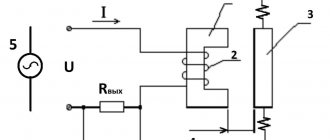
Overall these sensors work fine and are the cheapest option. A PIR sensor is used as a sensitive element; it creates an electric field proportional to thermal radiation.
But the sensor itself does not have a wide directionality; a Fresnel lens is installed on top of it.
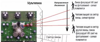
It would be more correct to say - a multi-segment lens, or multilens. Pay attention to the window of such a sensor, it is divided into sections; these are lens segments; they focus the incoming radiation into a narrow beam and direct it to the sensitive area of the sensor. As a result, radiation beams from different directions fall on the small receiving window of the pyroelectric sensor.
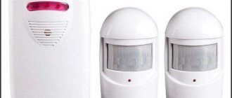
To increase the efficiency of motion detection, dual or quad sensors or several separate ones can be installed. Thus, the field of view of the device expands.
Based on the above, it should also be noted that the sensor should not be exposed to light from the lamp, and there should be no incandescent lamps in its field of view, this is also a strong source of IR radiation, then the operation of the system as a whole will be unstable and unexpected. IR rays don't travel well through glass, so it won't work if you're walking behind a window or glass door.
This is the most common type of sensor; you can buy it or you can assemble it yourself, so let’s look at its design in detail.
How to assemble an IR motion sensor with your own hands?
The most common option is the HC-SR501. It can be bought in a radio parts store, on Aliexpress, and is often supplied in Arduino kits. Can be used in conjunction with a microcontroller or independently. It is a printed circuit board with a microcircuit, wiring and one PIR sensor. The latter is covered with a lens, there are two potentiometers on the board, one of them regulates the sensitivity, and the second is the time at which a signal is present at the sensor output. When motion is detected, a signal appears at the output and lasts for the set time.
It is powered by a voltage of 5 to 20 volts, operates at a distance of 3 to 7 meters, and the output signal lasts from 5 to 300 seconds, you can extend this period if you use an NE555 monostable, a microcontroller or a time delay relay. The viewing angle is about 120 degrees.
The photo shows the sensor assembly (left), the lens (bottom right), and the reverse side of the board (top right).
Let's take a closer look at the board. There is a sensitive element on its front side. On the back there is a microcircuit, its wiring, on the right there are two trimming resistors, where the top one is the signal delay time, and the bottom one is the sensitivity. In the lower right part there is a jumper for switching between modes H and L. In mode L, the sensor produces an output signal only for the period of time set by the potentiometer. Mode H produces a signal while you are in the range of the sensor, and when you leave it, the signal will disappear after a time set by the upper potentiometer.
If you want to use a sensor without microcontrollers, then assemble this circuit, all elements are labeled. The circuit is powered through a quenching capacitor, the supply voltage is limited at 12V using a zener diode. When a positive signal appears at the sensor output, relay P is turned on through an NPN transistor (for example BC547, mje13001-9, KT815, KT817 and others). You can use a car relay or any other with a 12V coil.
If you need to implement some other functions, you can use it in conjunction with a microcontroller, such as an Arduino board. Below is the connection diagram and program code.
Ultrasonic
The emitter operates at high frequencies - from 20 kHz to 60 kHz. This leads to one problem - animals, such as dogs, are sensitive to these frequencies, moreover, they are used to scare them away and train them. Such sensors can irritate them and this causes problems.
The ultrasonic motion sensor operates on the Doppler effect. The emitted wave, reflected from a moving object, returns and is received by the receiver, while the wavelength (frequency) changes slightly. This is detected and the sensor produces a signal that is used to control a relay or triac and switch the load.
The sensor processes movements well, but if the movements are very slow, it may not work. The advantage is that they are not sensitive to changes in environmental conditions.
Laser or photo sensors
They have an emitter (for example, an IR LED) and a receiver (a photodiode of a similar spectrum). This is a simple sensor, it can be implemented in two versions:
1. The emitter and photodiode are mounted in the passage (controlled area) opposite each other. When you pass through it, you block the radiation and it does not reach the receiver, then the sensor is triggered and the relay is turned on. This can also be used in alarm systems.
2. The emitter and the photodiode are located next to each other, when you are in the range of the sensor, the radiation is reflected from you and hits the photodiode. This is also called an obstacle sensor and is successfully used in robotics.
Designation of the motion sensor in the diagram
MINISTRY OF INTERNAL AFFAIRS OF THE RUSSIAN FEDERATION
MAIN DIRECTORATE OF NON-DEPARTMENTAL SECURITY
TECHNICAL EQUIPMENT FOR OBJECT SECURITY SYSTEMS. CONVENTIONAL GRAPHICAL SYMBOLS OF SYSTEM ELEMENTS
This document was developed by the staff of the Research Institute: Yu.A. Safonov, A.V. Shepelev, S.N. Voronkov, N.A. Salapina, N.P. Ivanov with the participation of specialists from the private security departments at the Moscow City Internal Affairs Directorate and the Moscow Region Main Internal Affairs Directorate, as well as specialists and approved by the Main Directorate of Private Security (GUVO) of the Ministry of Internal Affairs of Russia on July 9, 1999.
The document has been assigned a symbol confirming its departmental affiliation.
This document includes the current RD 78.B0.01-99 “Technical means of facility security systems. Symbols of conventional graphic elements of systems. Part 1. Technical means of security and fire alarm systems.
1 AREA OF USE
This guidance document (RD) applies to conventional graphic symbols (GID) of technical means of newly developed and modernized security systems of objects (SBO) and can be used by design, construction and other organizations and enterprises involved in the design, construction, technical and organizational support of the functioning of SBO .
2 REGULATORY REFERENCES AND INFORMATION SOURCES
The following sources were used in developing this document:
GOST 26342-84 Security, fire and security-fire alarm systems. Types, main parameters and sizes
GOST R 50775-95 Alarm systems. Part 1. General requirements. Section 1. General provisions
GOST R 51241-98 Technical means of protection and security. Access control and management tools and systems. Classification. General technical requirements. Test methods
RD 25.953-90 Automatic fire extinguishing, fire, security and fire alarm systems. Symbols of conventional graphic elements of systems
Selection and application of television video monitoring systems:
Recommendations (R 78.36.002-99). - M.: Scientific Research Center "Security", 1999. - 51 p.
Directory of technical engineers and electricians of technical means of security and fire alarm systems. - M.: Scientific Research Center "Security", 1997.-262 p.
3 DEFINITIONS AND ABBREVIATIONS
The following definitions and abbreviations are used in this RD:
— Object Security System (FSS)
- a set of jointly operating technical means, methods and measures, created and maintained to ensure the normal operation of the object and to prevent and/or exclude accidental or unauthorized access of people and vehicles in order to disrupt the operation of the protected object.
— Security and fire alarm system (OPS system)
— a set of jointly operating technical means for detecting the appearance of signs of an intruder at protected objects and/or a fire at them, transmitting, collecting, processing and presenting information in a given form.
— Access control and management tools and systems (ACS)
— a set of jointly operating technical means of control and management (mechanical, electromechanical, electrical, electronic devices, structures and software) that have technical, information, software and operational compatibility and monitor and manage access of people and vehicles.
— Television surveillance system (STN)
— a set of jointly operating technical means that have technical, information, software and operational compatibility and carry out television surveillance.
— Module
- a unified unit, designed structurally as an independent product and performing a specific function in the technical means of the SBO.
— Panel
— a structural part of the control panel for SBO technical equipment, where control, monitoring and signaling organs are located.
Video surveillance system using autonomous cameras with Savecam cloud service.
Matrix 2 Megapixel 1/3″ Progressive CMOS Lens 4.3mm (included) Maximum resolution - 1280x1024 (30 fps) Removable IR filter IR illumination 20 m Video compression H.264/MJPEG Slot for MicroSD up to 32 GB IP66 housing Operating temperatures -40
+50 Power supply – 12V OS / 24V AC
The cost of the set is 30,000 rubles
4 GRAPHICAL SYMBOLS
4.1 Technical means of fire and security alarm systems
4.1.1 Wired systems and notification media
Graphic and letter symbols in electrical circuits
Just as it is impossible to read a book without knowing the letters, it is impossible to understand any electrical drawing without knowing the symbols.
In this article, we will look at the symbols in electrical diagrams: what types there are, where to find the decoding if it is not indicated in the project, how this or that element on the diagram should be correctly designated and labeled.
But let's start a little from afar. Every young specialist who comes to design begins either by folding drawings, or by reading regulatory documentation, or by drawing “this” according to this example. In general, normative literature is studied in the course of work and design.
It is impossible to read all the normative literature related to your specialty or even a narrower specialization. Moreover, GOST, SNiP and other standards are periodically updated. And each designer has to monitor changes and new requirements of regulatory documents, changes in the lines of electrical equipment manufacturers, and constantly maintain their qualifications at the proper level.
Remember Lewis Carroll in Alice in Wonderland?
“You have to run as fast as you can just to stay in place, and to get somewhere, you have to run at least twice as fast!”
This is not my way of whining about “how hard the life of a designer is” or boasting “look, what an interesting job we have.” That's not what we're talking about now. Given such circumstances, designers adopt practical experience from more experienced colleagues; they simply know how to do many things correctly, but do not know why. They work according to the principle “That’s the way it is here.”
Bottom line
At first glance, it seems that the designation of security sensors on the diagrams is a Chinese letter. In fact, even a superficial study of the topic will help you understand this issue and make it clear which symbols refer to which types of detectors, simplifying work with systems of this type.
To install an alarm system, first of all, it is recommended to call a certified team of installers who have a license to carry out this type of work. In the future, they can carry out maintenance of the security complex and carry out the necessary repairs if something suddenly breaks down. They can also provide a guarantee for their work.
But, if the owner is confident in his abilities and wants to carry out this process himself, then it is worth first studying all the instructions, becoming familiar with the diagrams and safety precautions.
You cannot connect the alarm system to the network without first turning off the electricity supply to the room.
YouTube responded with an error: The provided API key has an IP address restriction. The originating IP address of the call (87.236.20.136) violates this restriction.
Types and types of electrical circuits
Before talking about symbols on diagrams, you need to understand what types and types of diagrams there are. On July 1, 2009, GOST 2.701-2008 “ESKD. Scheme. Types and types. General requirements for implementation." In accordance with this GOST, schemes are divided into 10 types:
- Electric scheme
- Hydraulic circuit
- Pneumatic circuit
- Gas circuit
- Kinematic scheme
- Vacuum circuit
- Optical circuit
- Energy scheme
- Division scheme
- Combined scheme
Types of schemes are divided into eight types:
- Structural diagram
- Functional diagram
- Schematic diagram (complete)
- Connection diagram (installation)
- Connection diagram
- General scheme
- Layout diagram
- Combined scheme
As an electrician, I am interested in circuits of the “Electrical circuit” type. In general, the description and requirements for circuits are given in GOST 2.701-2008 using the example of electrical circuits, but since January 1, 2012 GOST 2.702-2011 “ESKD. Rules for the execution of electrical circuits." For the most part, the text of this GOST duplicates the text of GOST 2.701-2008, and other GOSTs also refer to it.
GOST 2.702-2011 describes in detail the requirements for each type of electrical circuit. When making electrical circuits, you should be guided by this GOST.
GOST 2.702-2011 gives the following definition of the concept of an electrical circuit: “An electrical circuit is a document containing, in the form of conventional images or symbols, the components of a product operating with the help of electrical energy, and their interconnections.” Next, GOST refers to documents regulating the rules for the implementation of conventional graphic images, letter symbols and designations of wires and contact connections of electrical elements. Let's look at each separately.
Graphic symbols in electrical diagrams
Regarding graphic symbols in electrical circuits, GOST 2.702-2011 refers to three other GOSTs:
- GOST 2.709-89 “ESKD. Conventional designations of wires and contact connections of electrical elements, equipment and sections of circuits in electrical circuits.”
- GOST 2.721-74 “ESKD. Conditional graphic designations in schemes. Designations for general use"
- GOST 2.755-87 “ESKD. Conventional graphic symbols in electrical diagrams. Switching and contact connection devices."
Conventional graphic symbols (UGO) of automatic circuit breakers, switches, contactors, thermal relays and other switching equipment that is used in single-line diagrams of electrical panels are defined in GOST 2.755-87.
However, there is no designation for RCDs and difavtomats in GOST. I think it will soon be reissued and the RCD designation will be added. In the meantime, each designer depicts an RCD according to his own taste, especially since GOST 2.702-2011 provides for this. It is enough to provide the UGO designation and its explanation in the explanations of the diagram.
In addition to GOST 2.755-87, to complete the circuit, you will need to use images from GOST 2.721-74 (mainly for secondary circuits).
All designations of switching devices are based on four basic images:
using nine functional features:
Motion sensor circuit.
A motion sensor circuit is a circuit of an electronic infrared device that allows you to detect the presence and movement of a person, and also helps to switch power to lighting devices and other electrical equipment.
Motion sensors are a great purchase for those who value the security of their home. They are not only convenient helpers, but also means of saving energy: sensors turn on the light when entering a room and turn it off when leaving.
The principle of operation of a motion sensor is very simple - when movement appears in its sensitivity area, the electrical circuit is closed and all devices connected to it are turned on. When there is no movement, the circuit automatically opens and all connected devices turn off automatically.
To easily calculate the required number of lamps, use the Calculator for calculating the number of lamps.
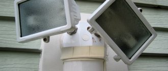
In this article we will look at a motion sensor for lighting the ultralight ask 1403 model with a viewing angle of 180 degrees.
As a rule, motion sensors are used to automatically turn on lighting, but these devices are also used for other purposes. There are also motion sensors with a viewing angle of 360 degrees.
Such a sensor is capable of detecting movement from any direction. This makes it a useful device if you own a store, office, or other facility that needs an alarm. In this case, the security alarm is connected in series to the sensor.
Adjustment
After installation, any sensor can be adjusted to the parameters of the room or the landscape design of the area. To do this, you can use the functionality on the case, the purpose of which we will consider in more detail.
Rice. 10. Motion sensor adjustment
Tilt angle.
The need to adjust the angle of inclination depends on the coincidence of the active zone with the desired path, sidewalk or porch area. If you need to move the active zone, you can adjust the sensor on the bracket. Some models use special handles for this. However, note that in models with a small vertical angle, the active zone should be adjusted not only by rotation, but also by the hanging height.
Rice. 11. Tilt angle adjustment
Sensitivity.
The sensitivity function allows you to adjust the light on depending on the size of the object. It is designated SEN on the body and can be adjusted from minimum to maximum. The lower the sensitivity you set, the worse the motion sensor will respond to small objects, for example, cats or dogs. As necessary, the sensitivity is increased so that the light turns on when the smallest member of the family moves.
Delay time.
This parameter specifies how long the light will remain on. To adjust it, you need to use the knob marked Time. As a rule, most motion sensors allow you to set the glow time from a few seconds to 10 – 15 minutes. But, if necessary, you can choose another range on the market.
Light level.
This option is available only to models with a built-in photo relay that responds to changes in time of day. On the equipment body it is marked with a LUX switch, which allows you to change the response limit depending on the decrease in the intensity of sunlight.
Motion sensor connection diagram to the lamp.
Installing a motion sensor is a fairly simple process. It is similar to connecting a regular switch. The motion sensor closes and opens the electrical circuit into which the lamp is connected in series. This is the similarity between the diagrams for connecting a motion sensor and a switch to a lamp .
When purchasing a motion sensor, you should be provided with standard installation, configuration and connection instructions. Another option for studying the connection diagram is to depict it on the device body.
Once you remove the back cover, you will find a terminal block and three colored wires that are connected to it - these will come out from inside the case. These wires are connected to terminal clamps. If a stranded wire is used for connection, special insulated lugs NSHVI are best suited.
Let's look at the features of the circuit diagram for connecting a motion sensor.
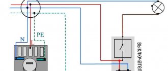
The sensor is powered from the network via two wires: phase L (brown wire) and zero N (blue wire). The phase after leaving the sensor arrives at one end of the incandescent lamp. The second end will be connected to wire N - zero.
When the sensor detects movement, it is triggered and the relay contact closes, the phase comes to the lamp, and it, accordingly, turns on.
Since the connection terminal block is equipped with screw clamps, the wires to the sensor must be connected using NShVI lugs.
It is better to connect the phase wire according to the schematic diagram. A similar motion sensor circuit should be indicated in the instructions.
After connecting the wires to the sensor, you can put on the cover and proceed to connecting the wires to the junction box.
Seven wires enter the distribution box: 2 supply wires, 3 from the sensor and 2 from the lamp. In the power cable, the phase has a brown wire color, and the zero is blue.
Let's move on to the wires. The cable connected to the sensor has a white wire that is phase, a green wire that is neutral, and a red wire that is connected to the load.
We connect the wires as follows: we connect the phase wire of the power cable together with the phase wire from the sensor (brown and white). After this, we connect the neutral wire from the power cable, the neutral wire from the sensor (green) and the neutral wire from the lamp.
Two wires remain unused: red from the sensor and brown from the lamp. We connect them together. This completes the motion sensor circuit . Obviously, there is nothing complicated about it.
This is how the motion sensor in the box is connected. I believe that figuring out the connection will not be difficult. Now you can apply power. As planned, the motion sensor reacts, closes the circuit and turns on the lamp.
Here is a diagram of the motion sensor. The sensor is connected to the lamp. Then we apply power, the sensor is triggered by movement and closes the circuit, turning on the lamp.
Designation of sockets
A socket is a switching device that is part of a plug connection, works in tandem with a plug, and is designed to connect electrical appliances to the network.
The designation of sockets in the drawings is done in a semicircle, from the convex part of which one or more lines extend, depending on the type of switching device.
The video shows the main symbols of electrical equipment:
Sockets according to the installation method are:
- External (for open wiring). They are mounted on a wall surface. They are indicated by an empty semicircle that does not have any additional lines inside.
- Internal (for hidden wiring). They are mounted inside the wall; to do this, you need to make a hole and insert a special socket into it, reminiscent of a shallow glass in shape. In the schematic representation of such switching devices, the semicircle inside has a line in the center.
Double sockets are often used in household networks. They are a monoblock in which there are two plug connectors (that is, you can connect two plugs from two different electrical appliances) and one installation location (installation is carried out in one socket box). The designation of a double socket on the electrical diagram looks like a semicircle with two lines on the outer convex side:
In modern household networks, sockets with grounding are increasingly used; they guarantee long-term reliable operation of electrical appliances and the safety of people in terms of electric shock.
These devices differ from ordinary ones in that they have a third contact to which the ground wire is connected.
This wire goes to the general distribution panel, where it is connected to a special ground terminal. The designation of such an outlet on the electrical diagram is as follows:
As you can see, grounding is indicated by a horizontal line, which is tangentially adjacent to the convex part of the semicircle.
It is no longer uncommon for a modern home to be supplied not with a single-phase electrical network, but with a three-phase one. Some electricity consumers require a voltage of 380 V (heating boilers, water heaters, electric stoves). To connect them, three-pole sockets with protective grounding are used. Switching devices of this type have five contacts - three phase, one neutral and one more for protective grounding. A three-pole socket is indicated with three lines on the outside of the semicircle:
And this is what the symbols for double sockets with protective grounding look like:
Sometimes you can see the designation of a socket, in which the semicircle inside is completely painted in black. This means that the switching device is moisture-resistant; it is equipped with a protective cover that prevents moisture or dust from entering the socket. The degree of protection of such elements is marked with special symbols:
- The two English letters IP denote the very concept that the outlet has a certain level of protection.
- Then follow two numbers, the first of which indicates the degree of protection from dust, the second - from moisture.
In the diagram, sockets with degree of protection IP 44-55 look like this:
If they have a protective grounding contact, then another horizontal line is added accordingly:
If you make a wiring diagram in specialized programs, then the video shows an example of a drawing in AutoCad:
Is it possible to connect a sensor with a switch?
Sometimes it becomes necessary to connect a motion sensor to a lamp along with a switch.
The switch turns on the light fixture, and the sensor, when motion is detected, performs the same task. Many people do not understand why connect two similar devices together. Let's find out how and why this is done?
If you need the lighting to be on regardless of the light level and the presence or absence of movement, then a motion sensor circuit , where the sensor is connected to a switch by connecting a regular single-key switch in the circuit in parallel with the motion sensor.
Video description
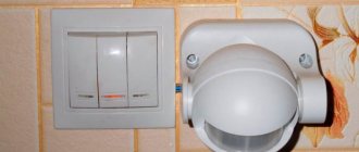
The video shows a connection diagram for a motion sensor installed instead of a switch:
Other connection schemes
There are many situations when you need to correctly approach the connection of motion sensors. For example, if you need to install this device in a long corridor with turns. It is clear that connecting a cable to each sensor requires large financial costs and a large amount of work. Therefore, a parallel installation scheme for two motion devices is proposed. That is, one common supply line is laid along the corridor. And motion sensors crash into it parallel to each other.
In this case, a person passing along the corridor first falls into the coverage area of one sensor, which turns on the first light bulb along the way. Then it leaves this zone, ending up in another neighboring one. And so on along the entire length of the corridor. That is, along the path of movement, the light bulbs light up and go out.
Another option is when it is necessary to turn on powerful lighting. After all, a standard device is designed for a maximum load of 1 kW. Or today the sensor is connected to ventilation systems or door opening systems. In this case, it is necessary to add magnetic starters or contactors to the circuit. The load is connected through the starter contacts, but the sensor terminals are connected to the coil through the phase circuit.
Diagram of parallel connection of two motion sensors Source i0.wp.com
Connecting a motion sensor with a switch - how to do it and why?
A switch connected in parallel to the sensor can be included in the circuit for continuous operation of the luminaire, regardless of the presence of movement in the response zone. The switch can repeat the operation of the sensor and allow you to forcibly control the lighting. This is a simple motion sensor circuit.
I’ll explain using an example of a situation where I need to connect a switch with a motion sensor. I live in a private house and come home late in the evening when it is dark outside, especially in winter.
So I installed a motion sensor for lighting and directed it to the entrance gate. When I enter the yard, the motion sensor is triggered and the lights turn on. I set it up for such a period of time that I could walk from the gate gate to the door of the house.
Let's assume that I need to leave the house at night (to go to the store, for example). Or I'll hear rustling in the yard and the lights aren't on. In addition, the sensor does not cover the entire yard. It turns out that I need to go outside and wave my hands in the dark until the motion sensor goes off?
That's why I needed to connect the switch along with the motion sensor. Now I just press the switch and the lamp lights up regardless of the sensor. Making such a connection is quite simple.
Now there is a motion sensor circuit, where the switch and sensor are connected together, but the lamp operates from the switch and turns on regardless of the sensor.
Installation and connection errors
Now let’s look at situations where the motion sensor suddenly starts working incorrectly. One of the main troubles is false inclusions. This is the situation here. If your device suddenly starts turning on spontaneously, then first of all you need to look for extraneous factors. For example, if the sensor is installed on the street, then there is a high probability that the movement of trees in the wind caused the trigger.
It's easy to check. It is necessary to close the device window with opaque tape. If it continues to “glitch”, then the reason is in it, or rather in its malfunction. If the lighting does not turn on, it means that you just need to configure the device correctly. Or move it to another place.
The next mistake is that the phase and zero have been swapped. In principle, for two-wire devices it makes no difference which wire passes through it. Its task is to open and close the circuit. But in terms of safety, the sensor must crash into the phase wire.
Ceiling sensor cannot be installed on a wall Source dachadecor.com
The third situation is when the light bulb suddenly turns on again after being turned off. This usually happens when incandescent light bulbs are installed in the lamp. After all, they do not immediately extinguish, because the filament must cool down. And this is additional radiation of infrared rays. The latter are picked up by the sensor and triggered by their impact. Therefore, the lamp must be installed so that it does not directly hit the window of the motion device.
The fourth situation is when the ceiling sensor is installed on the wall, or vice versa. That is, when purchasing a device, you should know that manufacturers offer ceiling and wall models with different viewing angles. This means they work differently in terms of coverage of the traffic area. Therefore, ceiling models cannot be mounted on a wall, and vice versa.
Fifth, the instrument window is dirty or has a crack. Not everyone knows that there is more than just transparent glass installed on the sensor window. This is the so-called Frenkel lens. It is she who focuses infrared radiation, transmitting signals further along the chain. Any defect or small speck of dirt makes the motion device operate incorrectly.
And other situations of incorrect operation of the motion sensor: glare from windows, a strong gust of wind, operation of an external air conditioner unit, convection of heating devices, movement of warm air.
What types of motion sensors are there?
- IR detectors respond to thermal radiation emitted by surrounding objects. If they move, this is caught by special lenses. It is a passive motion sensor, as it does not emit anything into space. Resistant to sound and vibration. It is not recommended to install them in places where light rays or heat sources will be directed at the sensor. The most inexpensive and simple devices are recommended for everyday use in lighting systems. In the diagrams, the OPS is depicted as a black square with a white triangle on its right side, the top of which reaches the center of the figure;
- An ultrasonic detector is an active device, like the next type of sensor. It transmits ultrasonic waves into the environment, which then return to the device, or go to the receiver if it is located separately from the transmitter. By the nature of the changes in these waves, the device judges the movement within its visibility zones. It is not recommended to use sensors of this type in rooms where there are animals, as they hear ultrasound and this causes them anxiety. On security alarm diagrams it looks like a black square, across the entire area of which there is a white triangle, pointing to the left. There is a line from its top to its base;
- Microwave devices emit radio waves. They are more accurate and sensitive than their ultrasonic counterparts. Signals from such a sensor can pass through obstacles, and the level of radiation from them is so low that it will not cause any harm to living beings. Resistant to vibration and heat. The schematic representation of this device is similar to the ultrasonic one, with the only difference being that it is completely white;
- combined detectors require the presence of several types of sensors within one system, which makes the device the most accurate and reduces the number of false alarms to a minimum. The symbol for this sensor looks like a white square with a black triangle on its right side, from the top of which there is a line to the opposite part of the square;
- perimeter systems are located along the perimeter of the territory, covering a certain area, triggered when an intrusion into the coverage area occurs;
- peripheral ones can be installed on the walls of buildings, fences, inspecting areas in their field of view;
- indoor ones are intended for indoor use, have a less durable and resistant body and do not have such a wide temperature range at which they can remain operational;
Room motion sensor
- single-position devices are a receiver and transmitter in one housing;
- two-position - different shells for the translator and the catcher, which implies their placement in different places so that the required area is located exactly between them;
- multi-position systems are equipped with several devices, which makes it possible to monitor a fairly large area using one set of security devices;
- overhead sensors are the simplest, mounted on any flat surface;
- built-in ones are more expensive models; they allow you to disguise them if there is a need to hide them from prying eyes, or you need to maintain the design integrity of the room. They are mounted on the same plane as the work surface, which makes it possible to disguise them if the owner so requires;
- Wired detectors operate from the network and transmit a signal through wires. This results in a more stable transmission signal, which may not be available in some cases when using their wireless counterparts. In the event of a power failure, the device can be protected from shutdown by being connected to a backup generator. This is mainly practiced in large organizations, where it is undesirable to remain without power for a long time (for example, food warehouses with refrigerators), as well as in private homes;
- wireless and stand-alone devices are installed if it is not possible to run a cable to the installation site. In this case, power is supplied from a battery located inside the device. And data transmission is carried out over a wireless network - Wi-Fi or GSM. This communication method is highly dependent on electromagnetic interference, the number of obstacles between the receiver and transmitter, and can also respond to changing weather conditions. But, in general, this method is the fastest and most accurate.
Varieties
The division of motion sensors for turning on lights into types is carried out according to several criteria. Based on their operating principle, they can be divided into:
- Infrared - based on measuring the temperature of objects falling within the coverage area of the motion sensor. The main disadvantage is a false reaction to elements of the heating system or incandescent lamps located in close proximity.
Rice.
2. Infrared sensor Ultrasonic – operate based on the Doppler effect. The emitted sound wave in the frequency range from 20 to 60 kHz is not audible to the human ear in accordance with clause 2.1.1.3 of GOST R 50030.5.2-99. When faced with an obstacle, ultrasound is reflected and returns to the receiver, which sends a signal to an electronic key or relay.
Rice. 3. Ultrasonic sensor
Microwave - use a special antenna that sends a high-frequency signal into the surrounding space. When a signal collides with a moving object, a reflected signal is generated that returns to the sensor. Today these are the most sensitive, but also the most expensive models for turning on the light.
Rice. 4. Microwave sensor
- Laser - usually consist of an LED and a photodiode mounted in the controlled area. The LED emits a signal that spreads into the surrounding space. As soon as an object appears in the area of action that blocks the light flow, it is reflected and perceived by the photodiode. From which the signal is supplied to the actuator of the motion sensor.
- Tomographic - use radio waves to diagnose space. Unlike other models, they are able to penetrate walls, structural elements and other obstacles. Used to turn on lighting in large areas, shopping centers, etc.
Depending on the method of interaction with moving objects, motion sensors can be active, passive or combined . Active ones independently emit measured signals, and then perceive them. Passive ones are focused on the human body’s own radiations or are driven by their interaction with the environment. Combined ones consist of an active emitter installed on one side and a passive receiver located on the other side.
Depending on the installation location, motion sensors are divided into devices for external and internal use . The first ones are intended for use outdoors. The latter are used for placement indoors, sometimes under canopies, on verandas, covered terraces and patios.