Although direct current is of better quality than alternating current, the latter is mainly used in electrical networks. The reasons are cheaper engines (generators), minimal losses when transporting electricity over long distances and the ability to convert current by transformation.
Next, let's look at what AC electrical circuits are and what they consist of.
AC electrical circuits
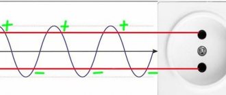
Alternating current, unlike direct current, changes direction and magnitude with a certain periodicity. It is generated by rotating a coil of wire in a magnetic field or, conversely, a magnetic field with a stationary coil.
The induced EMF depends on the sine of the angle through which the generator rotor is rotated. Therefore, all variable electrical quantities are sinusoidal. There are two types of alternating current circuits - single- and three-phase.
AC parameters:
- amplitude: maximum deviation from zero. It is achieved when the coil plane is positioned perpendicular to the field lines. At the moment when the plane of the coil and the lines of force become parallel, the emf drops to zero, then changes sign;
- frequency: the number of complete cycles per second (mainly a current with a frequency of 50 Hz is used);
- instantaneous value: the value of the parameter at a given time;
- effective value (see below).
Disadvantage of alternating current: at low frequencies it is more dangerous for living organisms than direct current.
Single-phase
In a single-phase circuit, the generator has one winding for inducing EMF and one conductor is connected to it. There can be several current sources, but they must operate in the same phase and at the same frequency.
Three-phase
In the stator of a 3-phase circuit generator there are 3 windings for induction, shifted relative to each other by an angle of 120 n degrees, where n is the number of pole pairs.
Accordingly, the EMF induced in each winding differs in phase by an angle of 120 degrees (electric angle). When each winding is connected separately, 6 wires are required to transmit energy. The system is called disconnected and today it is not used due to the increased costs of materials.
A connected system is more economically feasible when the windings are connected in one of two ways:
- "star" . The windings on one side are closed at one point. This makes it possible to use one neutral wire, common to all phases, that is, the system turns out to be 4-wire. And if the currents in the phases are equal (symmetrical load), there is no need to use a neutral wire: the currents cancel each other (their vector sum is zero). In this case, a 3-wire system is used;
- "triangle" . The windings form a closed circuit: each end is connected to the beginning of the next. In each phase, a linear voltage is formed that is equal to the phase voltage. But the value of the phase current will be 1.72 times lower than the linear one.
A three-phase power supply system is superior to a single-phase power supply system in the following ways:
- Fewer materials are required for the manufacture of power cables;
- For one installation, two voltages are available: phase (phase - neutral) and linear (phase - phase). That is, when changing the load connection diagram from “star” to “triangle”, two power levels are obtained;
- It is possible to obtain a rotating magnetic field, which reduces the cost of the design of electric motors and other devices. To do this, three windings connected to different phases are placed equidistantly in the motor stator;
- the system is balanced. For example, 3-phase fluorescent lamps almost do not flicker, unlike 1-phase ones. Such a lamp has three lamps or groups of lamps connected to different phases. When the luminosity of one lamp decreases, the neighboring one flares up. Mutual compensation occurs.
Thanks to the balance, the load on the generator is equally distributed and it lasts longer.
Advantages of single-phase connection
Let's consider the advantages of a single-phase connection.
| Advantages | Description |
| Easy installation | As mentioned above, a single-phase network has only three wires. Therefore, installing a single-phase network is not as difficult as installing three-phase wiring. |
| Low cost | A single-phase electrical network requires cheaper components: single-phase circuit breakers, RCDs, voltage relays, etc. |
As for the disadvantages of a single-phase connection, we can only highlight its low power and the inability to power three-phase consumers.
Structure
An electrical circuit is a set of devices and elements aimed at delivering current to the consumer and converting it into another type of energy: heat, light or mechanical work.
There are three parts in the circuit:
- power supply;
- transmitting part: wires, switches, transformers, stabilizers, etc. Everything that is used to transmit, transform electrical energy and maintain its quality at the proper level;
- consumers: lamps, electric motors, heaters, etc.
The power source - generator, battery, solar panel - is called the internal part of the circuit, the remaining components are called external. The source is also called an active element, others - passive. The electrical circuit functions only in a closed form, that is, in a continuous form. When opened, the current in it drops to zero, although the section on the generator or battery side remains energized.
Based on the number of pins, circuit components are divided into two types:
- bipolar : have one pair of terminals. Example - diode, resistor;
- multi-terminal : have more than two terminals. Example - transformer (4 pins).
Processes in an electrical circuit are described by Ohm's and Kirchhoff's laws.
The components in it are connected in three ways:
- sequentially;
- parallel;
- in a combined way.
The following terms are used:
- branch _ A section of series-connected elements in a parallel or combined circuit. The laws of electrical engineering state: the current strength within a branch is the same, regardless of the resistance value of its constituent components, and the total resistance of a branch is equal to the sum of the resistances of all its components. In a circuit with only a series connection of components, no branches are distinguished; it is called an unbranched circuit;
- knot . The place where the chain branches. It is generally accepted that the sum of currents converging at a node is equal to the sum of currents emanating from it. The voltage drop for parallel branches between the branching and convergence points is the same;
- outline . A set of branches that represents a closed path for current.
According to functionality, individual parts in the structure of the electrical circuit are divided into the following types:
- power _ Includes elements that generate, conduct, convert and consume electricity;
- auxiliary _ Various additional devices not related to the power section. For example, reactive power compensation installations, fuses;
- measuring _ The devices related to this part allow you to monitor the parameters of the network and devices connected to it;
- manager _ Equipment for adjusting device parameters or turning them on/off.;
- signaling . Reports changes in network parameters by turning on alarm devices.
According to complexity, electrical circuits are divided into:
- simplest: source connected to consumer;
- simple: contain one circuit;
- complex: have several circuits.
In complex chains there are:
- multi-circuit;
- multi-node;
- planar;
- volumetric.
Zeroing in the apartment
This is the connection of the neutral cable with the neutral conductor of the electrical network and the device body. It is assumed that the procedure ensures faster disconnection of the device from the network when touching a dangerous place, if the voltage is above a certain threshold. But it is associated with an additional danger: if there is a zero break, all devices connected at that moment to the apartment’s network will have a phase (and not zero) on the surface, which creates a significant threat to the health of residents. Therefore, such installation work is strictly regulated.
Knowing what exactly is called a phase in an electrical network and how to detect it is extremely important when carrying out electrical installation work. Otherwise, there is a high risk of harming the health of the tenants or the condition of electrical appliances.
Circuit calculation
The main purpose of the calculation is to determine in individual sections of the chain:
- tension;
- current strength;
- power and phase angle.
In simple cases, when only a resistive load is present in the circuit, the alternating current, which is inconvenient for calculations, is replaced by the so-called effective value. This is a direct current equivalent to a given alternating current, that is, releasing the same amount of heat.
For sinusoidal variables of current and voltage, the following expressions are valid:
- I = Imax / root of 2 = Imax / 1.41;
- U = Umax / root of 2 = Umax / 1.41;
- where I and U are the effective values of current and voltage, respectively;
- Imax and Umax are the amplitudes of current and voltage, that is, their maximum deviations from zero.
The standard voltage in a household electrical network is 210-230 V - this is the effective value. The actual value ranges from -296 to 296 V (210 V) or -324 to 324 V (230 V).
Similarly, when they say that a 2.2 kW device consumes a current of 10 A, they mean the effective value, while its real value ranges from -14 to 14 A.
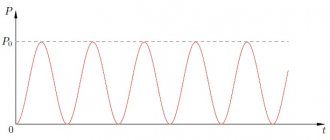
Graph of sinusoidal alternating current
The task becomes more complicated when the complex contains the following elements:
- inductors: EMF of self- and mutual induction occurs;
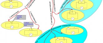
- capacitors: currents appear - charging and discharging.
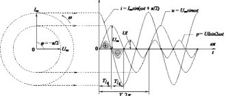
Under the influence of these processes, voltage and current are shifted in phase relative to each other, the difference is 90 degrees, while in systems:
- with inductance – U leads I;
- with capacitors - the voltage lags behind the current.
In such circuits, the same laws apply as in DC circuits, but it is impossible to replace alternating voltages and currents with effective values; there are two ways:
- handling instantaneous values of variables;
- recording them in vector (complex) form.
In the first option, you have to deal with trigonometric equations, since the instantaneous values of the current and other parameters are expressed through the function “sin(ωt)”, where ω is the angular frequency of rotation of the generator rotor, t is time. Solving such equations is difficult, which is why this path is unpopular. It is easier to operate with vector quantities.
This method is called symbolic. When composing equations, vectors are written in the form of complex numbers, given a conditional positive direction for current, voltage and emf.
In algebraic form, a complex number looks like this: A = a + jb, where:
- A is the real (real) part;
- j is the imaginary unit;
- b is the imaginary part.
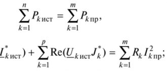
The letter expressing the electrical parameter is underlined in the complex notation. To check the correctness of the circuit calculation, a balance of active and reactive powers is drawn up.
Calculation using the symbolic method is similar to calculating a DC circuit, only all real electrical parameters are expressed in complex numbers. The result of the calculation—currents and voltages in sections of the circuit—are also written in complex form.
Generation and transformation
The principle of generating electricity is simple. If a magnetic field rotates along a stationary set of coils of turns of a conductor or, conversely, a coil rotates around a stationary magnetic field, then due to the phenomenon of electromagnetic induction, a potential difference arises at the ends of the windings. With each change in the angle of rotation resulting from the described circular motion, the output voltage will also change in both magnitude and direction.
The described conditional generator at a constant angular speed of rotation of the shaft produces a sinusoidal AC with a waveform that is no different from that supplied in a household network. Real generators are much more complex, but operate on the same principles of electromagnetic induction.
These same laws help not only in the production of AC, but also in its transmission and distribution. Voltage conversion by power companies cannot be accomplished without electrical machines called transformers.
This is why Tesla's invention was so important to the revolution in electricity transportation.
Any transformer consists of the following elements:
- primary and secondary windings;
- core.
The word “primary” is used for the winding to which the electrical voltage that needs transformation is applied. The induced voltage on the secondary coil is always equal to that applied on the primary, multiplied by the ratio of turns of the secondary to the primary. The transformer allows you to change the voltage step by step.
Conclusion
Both power supply options are safe only if all necessary installation requirements are met.
As a rule, in the private sector, the user can choose which type of electrical network is more suitable for him. But there is a main determining factor - the maximum permitted power, which is indicated in the technical specifications for connecting the house to the electrical network. For example, if a SNT has a limitation of 5 kW of power (from the SNT itself or the supply networks), then it is regulated exclusively for one phase. As a rule, this is done to make it easier to divide all SNT houses into 3 phases (for example, with 300 plots, each phase is distributed among 100 houses), knowing for sure that none of these houses will be able to consume more than 5 kW and overload any out of phase, causing imbalance.
A three-phase network allows you to get three phases, but each with 5 kW, which will triple the capabilities (15 kW in total), and, again, each phase remains limited to consumption of no more than 5 kW, which will not allow a particular house to cause imbalance.
Considering all the positive and negative aspects of a three-phase network, its installation in a house is necessary only in cases where the connection is planned:
- a large number of single-phase consumers;
- powerful three-phase loads (for example, heating equipment or hobs);
- three-phase power tools (for example, for organizing a workshop in the house).
If we talk about electrical protection, then for both three-phase and single-phase networks, many users install voltage stabilizers that protect the load from unstable mains voltage. This is especially true for private houses, cottages and dachas, where low-quality network voltage is often found. The voltage stabilizer becomes as integral an element of the home's electrical system as an input circuit breaker, RCD or electric meter.
Power distribution system
Initially, the voltage is always three-phase. By “initially” I mean a generator at a power plant (thermal, gas, nuclear), from which a voltage of many thousands of volts is supplied to step-down transformers, which form several voltage stages. The last transformer lowers the voltage to a level of 0.4 kV and supplies it to end consumers - you and me, apartment buildings and the private residential sector.
Large enterprises with power consumption of more than 100 kW usually have their own 10/0.4 kV substations.
Visually:
Three-phase power supply – stages from generator to consumer
The figure shows in a simplified way how from generator G a voltage (everywhere we are talking about three-phase) 110 kV (can be 220 kV, 330 kV or another) is supplied to the first transformer substation TP1, which lowers the voltage for the first time to 10 kV. One such transformer substation is installed to power a city or region and can have a capacity of the order of a few to hundreds of megawatts (MW).
Next, the voltage is supplied to the second stage transformer TP2, at the output of which the end-user voltage is 0.4 kV (380V). The power of transformers TP2 is from hundreds to thousands of kW. From TP2, voltage is supplied to us - to several apartment buildings, to the private sector, etc.
Such voltage level conversion stages are necessary in order to reduce losses during the transportation of electricity. Read more about losses in cable lines in my other article.
The circuit is simplified, there may be several steps, the voltage and power may be different, but the essence does not change. There is only one final voltage of consumers - 380 V.
Disadvantages of three-phase input
A three-phase connection also has its significant disadvantages. Let's take a closer look at them.
| Flaws | Description |
| Uniform load distribution across phases | To avoid phase imbalance, it is necessary to evenly distribute single-phase consumers across three phases. Therefore, when designing three-phase electrical wiring in a private house, great attention must be paid to proper load distribution. |
| Power limitation for single-phase loads. | For example, if the allocated power per house is 15 kW, then each phase will have 5 kW with a maximum current of no more than 22 A. In this case, a problem will arise in connecting a more powerful single-phase load. |
| High price | Laying a three-phase network inside a house will be much more expensive than a single-phase one. The use of cables and wires with a large number of cores (each phase must be routed with a separate cable), the installation of a more modernized electrical panel, a three-phase meter, circuit breakers, as well as special protection devices - all this will affect the final cost. |
| Mains voltage sags | Some users believe that if one of the phases subsides, you can freely use the other two. But in this case they can easily be overloaded. To safely switch phases, you will need an electronic switch. |
| Features of connecting consumers with three-phase motors | To connect consumers with three-phase motors, you will need a special device to find the correct phase rotation (phasing). True, this phasing must be observed only on the motor itself when connecting. |
Determination of phase-zero loop resistance
To ensure the normal functioning of electrical appliances and check machines, it is necessary to periodically measure the resistance of the phase-zero loop. Because the primary causes of breakdowns of lighting devices are network overloads and short circuits. Measuring resistance allows you to quickly identify a malfunction and prevent a similar situation.
Not everyone knows what the concept of a “phase-zero loop” is. This phrase hides a circuit formed as a result of connecting the neutral wire located in a grounded neutral. The closure of this electrical network forms a phase-zero loop.
Resistance in this circuit is measured using the following methods:
- drop in voltage level in a disconnected circuit
- a drop in voltage level due to the resistance of an increasing load
- using a professional tool to interpret the short circuit in the circuit
The second method is used most often, as it is convenient, the ability to quickly measure resistance, and also safe.
Cable color marking
This is one of the simplest methods. To determine what phase and zero are by color, you need to clearly know which shades correspond to what. You can use information about the standards adopted in the country.
It's no secret that each wire has an individual color. Therefore, recognizing zero should not be a particular problem. The knowledge gained will allow you to easily cope with the installation of a lighting fixture or installation of an outlet. This method is especially relevant for new buildings. After all, there, as a rule, wires are laid by experienced specialists who strictly comply with norms and standards. The IEC 60446 standard, adopted on the territory of the Russian Federation in 2004, strictly regulates the separation of phase, grounding and zero by color.
It is worth considering that:
- if the wire has a blue or blue-white tint, we can safely say that this is a working zero
- the protective zero is represented by cables in a yellow-green sheath
- other colors are characteristic of the phase. It can be red, brown, white or black. Other options are also possible.
This designation is successfully used in most cases. But if the wiring is old, or there are doubts about the professionalism of electricians, it is more advisable to use additional methods.
How to distinguish phase, zero, ground
The easiest way to determine the purpose of the conductors is by color marking. In accordance with the standards, the phase conductor can have any color, the neutral can be blue, and the ground can be yellow-green. Unfortunately, when installing electrics, color coding is not always observed. We must not forget the likelihood that an unscrupulous or inexperienced electrician can easily confuse phase and zero or connect two phases. For these reasons, it is always better to use more precise methods than color coding.
You can determine the phase and neutral conductors using an indicator screwdriver. When the screwdriver comes into contact with the phase, the indicator will light up, as electric current passes through the conductor. Zero has no voltage, so the indicator cannot light up.
You can distinguish zero from ground using a dial tone. First, the phase is determined and marked, then with a continuity probe you need to touch one of the conductors and the ground terminal in the electrical panel. Zero will not ring. When you touch the ground, a characteristic sound signal will be heard.
Advantages of three-phase connection
Let us note the main advantages of a three-phase network.
| Advantages | Description |
| Universal use | Both single-phase loads (220 V) and electrical installations operating on line voltage (380 V) - machine tools, welding machines and other specialized high-power electrical equipment - can be connected to a three-phase network. |
| Connecting a large number of electrical appliances | Higher output power – from 15 kW, which allows you to connect a large number of electrical appliances. |
| Rational phase distribution | For a large household, introducing a three-phase network into a private house is more rational. Since there is a choice of distributing 3 phases between rooms or consumers in the house. For example, you can use one phase for home electrical wiring, a second for powerful household appliances, and a third for utility rooms. |
