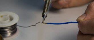
There are various types of electric motors installed in household appliances and equipment. These differences depend on the operating conditions, purpose and functions they perform. For example, commutator motors are used in electric drills, mixers, food processors, vacuum cleaners, washing machines and other devices with frequent changes in shaft rotation speed. If it is necessary to ensure long-term stable operation, then such equipment uses asynchronous electric motors, which are most suitable for small home-made machines. However, in all cases it is often necessary to check the motor armature at home.
Typical faults
The electric motor armature is not subject to wear under normal operating conditions. Only the brushes are replaced, measuring the permissible length. But under prolonged loads, the stator windings begin to heat up, which leads to the formation of carbon deposits.
Due to mechanical stress, the armature of the electric motor may become distorted if the bearing units are damaged. The engine will work, but gradual wear of the lamellas or plates will lead to its final failure. But to save expensive equipment, it is often enough to carry out preventive repairs and the device can be used for a long time.
Negative factors affecting the armature of an electric motor include moisture getting on metal surfaces. Prolonged exposure to moisture and the appearance of rust are critical. Due to red accumulations and dirt, friction increases, which increases the current load. The contact parts get hot and the solder can flake off, creating an intermittent spark.
The service center can help, but this will require certain costs. You can deal with the breakdown yourself by reading the question: how to check the armature of an electric motor at home. For diagnostics you will need a device that measures resistance and tools.
Checking the rotor with a multimeter
The procedure for checking the rotor for interturn short circuit includes two stages:
- determining the presence of a short circuit;
- detection of a specific fault location.
To establish the very fact of the presence of an interturn short circuit, you need to set the multimeter to the ringing mode. To do this, place the switch handle on the speaker symbol. One probe is applied to the lamellas, and the second to the armature winding body. If a beep sounds, it means there is an interturn short circuit. And we need to start searching for it.
To find the specific section of the winding in which the short circuit has occurred, the multimeter is switched to resistance measurement mode and the limit is set to 200 Ohms. Next, probes measure the resistance between the windings located in the vicinity. Then the slats are tested. On a working armature, all resistance readings should be the same. In the closed part of the winding, the resistance will tend to zero.
How is a fault diagnosed?
Checking the motor armature begins with identifying the fault itself. Complete failure of this unit occurs due to scattered commutator brushes, destruction of the dielectric layer between the plates, and also due to a short circuit in the electrical circuit. If there is sparking inside the device, it is concluded that the current collectors are worn or damaged.
Sparking of the brushes begins due to the appearance of a gap at the point of contact with the commutator. This is preceded by a fall of the device, a high load on the shaft when jammed, as well as a violation of the integrity of the solder on the winding terminals.
A malfunction on a running electric motor manifests itself in typical conditions:
- Sparking is the main sign of a malfunction.
- Rumble and friction when the armature rotates.
- Noticeable vibration during operation.
- Changing the direction of rotation when the armature passes a trajectory of less than a revolution.
- The appearance of a smell of melting plastic or strong heating of the case.
Detection of inter-turn short circuit
You can understand that the rotor turns may have shorted out not only by the sound and smell of the running engine, sparking on the brushes and its uneven heating. There are other ways to determine this malfunction. True, this is done with the electric motor disconnected from the network. These are the methods.
- visual inspection of the anchor;
- measuring the load on each rotor phase using current clamps;
- use of a special tester;
- use of a homemade throttle;
- check with a multimeter.
Checking the rotor for interturn short circuit with a multimeter will be discussed further. But before that, let’s briefly analyze the device and operating principle of the multimeter.
What to do if the listed deviations in work occur?
The rotation speed of the electric motor armature is maintained constant. At idle speed the malfunction may not appear. Under load, friction is compensated by an increase in current flowing through the windings. If deviations in the operation of the angle grinder, drill, or starter become noticeable, then you need to remove the voltage supply.
Continued use of the devices may result in a fire or electric shock. First of all, it is recommended to inspect the product body, evaluate the wiring for integrity, the absence of melted parts and damage to the insulation. Check the temperature of all parts of the device by touch. Try to rotate the armature by hand; it should move easily, without jamming. If the mechanical parts are intact and there are no contaminations, proceed to disassembly.
Diagnostics of internal parts
The armature winding of the electric motor should not have carbon deposits or dark spots similar to the consequences of overheating. The surface of the contact parts and the gap area should not be dirty. Small particles reduce motor power and increase current. Do not disassemble devices with a plug connected to the network for safety reasons.
It is recommended to film the disassembly process to eliminate complications during the reverse process. Or you can write down each step of your actions on a piece of paper. Some wear of brushes and lamellas is allowed. But if scratches are found, you should find out the cause of their origin. Perhaps this was caused by a crack in the case, which can only be noticed under load.
Multimeter
A multimeter is a device designed to measure the current consumed by an electrical appliance, the resistance of the conductor and the voltage of electricity in the network. That is, an ohmmeter, an ammeter and a voltmeter are connected in it. The device includes two wires with plugs at one end and probes or clamps at the other. These wires are colored red and black. The plug of the black wire is always inserted into the negative socket, marked on the multimeter body with the letters “COM” or the minus sign “–”. The red wire is connected to one of the two remaining sockets, depending on what needs to be measured.
A rotating switch is located on the electronics-filled housing. With its help, the operating mode of the device and the measured limit are set. Information about the measurement results is displayed on the display or on a digital scale with an arrow. Depending on this, multimeters are divided into two types: digital and analog. Digital devices are more modern and accurately record readings that are easy to read. Analog multimeters, although less common now, still have some positive qualities, among which professionals highlight greater sensitivity to changes in the characteristics of the electromagnetic field.
Before starting to check for interturn short circuit, it is necessary to disassemble the engine and prepare the armature for testing.
Working with an ohmmeter
Sincere could occur due to the loss of electrical contact in one of the lamellas. To measure resistance, it is recommended to place probes on the side of the current collectors. While rotating the motor shaft, observe the dial readings. The screen should show zero values. If the numbers slip by even a few ohms, then this indicates carbon deposits. When an infinite value appears, an open circuit is judged.
Regardless of the results, you should next check the resistance between each adjacent lamellas. It should be the same for each measurement. In case of deviations, you need to inspect all the connections of the coils and the contact surface of the brushes. The brushes themselves should wear evenly. If chipped or cracked, they must be replaced.
The coils are connected to the core by wiring that may have come loose. Solder often does not withstand shock from drops. In a starter, the current through the contacts can reach 50A, which leads to burnout of poor-quality connections. External inspection determines the location of damage. If no malfunction is found, then measure the resistance between the lamella and the coil itself.
Features of disassembling the electric motor
Even before you start trying to remove the rotor from the electric motor, you can try replacing the brushes. Of course, this should be done only if their condition makes it clear that the elements have served their purpose. After all, excessive sparkling, loss of power and the smell of burnt wiring can be a consequence of wear on the current collection brushes. And only after replacing them has not brought results, you need to take on the rotor and stator.
You need to disassemble the engine very carefully so as not to damage the components and serviceable winding. It is recommended to pay attention to the selection of a screwdriver, since a tool of the wrong size can damage the bolt heads and will require a lot of effort to unscrew them. Novice electricians are advised to take photographs of all stages of disassembling an electronic device, so that later there will be no problems with assembling the motor. Moreover, electric motors are often installed in technically complex products with many different fasteners.
If you don't have an ohmmeter?
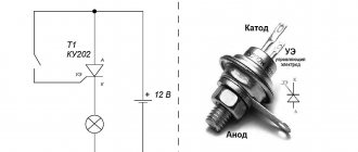
If you don’t have a multimeter, you will need a 12 Volt power source and a light bulb for the appropriate voltage. Any car enthusiast will have no problems with such a set. The positive and negative terminals are connected to the plug of the electrical appliance. An incandescent lamp is placed in the gap. The result is observed visually.
The armature shaft is rotated by hand, the lamp burns without jumps in brightness. If attenuation is observed, the engine is faulty. Most likely, an interturn short circuit has occurred. Complete disappearance of the glow indicates a break in the circuit. The reasons may be non-contact of the brushes, a break in the winding, or a lack of resistance in one of the lamellas.
Device
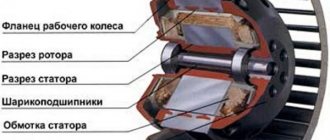
To correctly diagnose armature faults, it is important to know the device and the principle of its operation . The main elements of the armature are a round core, consisting of a set of electrical steel plates and a winding wound into its grooves in a certain way. Two armature windings are placed in each of the grooves according to a special pattern . The first and last turns of one of the windings are in the same groove and are closed to one lamella.
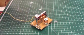
Rotor for Makita angle grinder 9069 MAX. Photo 220Volt
The core is pressed onto the rotor , which rotates under the influence of forces arising in the electromagnetic field formed by the armature windings and the stator coils working in tandem with it. In grinders, the anchor is an assembly unit with a drive gear located at one end of the shaft, and a commutator unit at the opposite end.
How to “revive” a faulty device?
Repair of the electric motor armature begins only after full confidence in the malfunction of the unit. Scratches and chips on the lamellas are removed by circular groove of the surface. Carbon deposits and soot can be removed with cleaning agents for contact electrical connections. Broken bearings are repressed and replaced with new ones. It is important to balance the shaft during assembly.
Rotation should be easy and without noise. Damaged insulation is restored; ordinary electrical tape can be used. It is better to solder connections that cause suspicion. If there are problems with the armature coils, it is recommended to resort to rewinding, which you can do yourself.
Preparing the rotor for testing with a multimeter
Once you have finished removing the rotor from the electric motor, you need to thoroughly clean it. To do this, use a rag lightly moistened with alcohol, which is used to wipe the slats. Even if there is no extraneous dirt or moisture, graphite dust from the brushes will still be present.
If you do not thoroughly clean it, both from moisture and from graphite deposits, this can affect the accuracy of the results, showing a short circuit where there is none. Sometimes, with heavy carbon deposits, it is recommended to use sandpaper. This is not worth doing. Coarse abrasives will scratch the lamellas and may change the geometry of the commutator. Brushes on such a surface will take a very long time to rub in and wear out intensely. It's better to use a school eraser. It is specially made to erase the pencil mark left by the graphite rod.
After cleaning the anchor, you must inspect it carefully. First, pay attention to ensure that there is no heavy carbon deposits on the lamellas. Then they look for visible traces of a short circuit or breaks in the coil turns. Analysis of contact strength is the next stage of inspection. All connections of the winding wires to the lamellas on the commutator are checked. If traces of burning or excessive wear of the collector are found, the anchor can be scrapped. Serious damage is difficult to repair and it is easier to buy a new part. If the armature seems to be working properly, then you need to proceed to directly checking for an interturn short circuit using a multimeter.
Restoration of coils
You can rewind the armature of an electric motor in a garage, you just need to be careful when applying each turn. Copper wiring is selected similar to the wound one. The cross-section cannot be changed; this will lead to a violation of the engine speed limits. Dielectric paper will be needed to separate the windings. The coils are finally filled with varnish.
You will need a soldering iron and skills to use it. The joints are treated with acid, and rosin is used to apply tin-lead solder. When dismantling the old winding, count the number of turns and apply a similar amount of new winding.
The body must be cleaned of old varnish and other inclusions. A file, sandpaper or torch is suitable for this. Sleeves are made for the anchor; the material is electrical cardboard. The resulting blanks are placed in the grooves. Wound coils should be made with right-hand turns. The terminals on the collector side are rewound with nylon thread.
Each wire is soldered to the corresponding lamella. The assembly should end with regular measurements of the resistance of the contact connections. If everything is normal and there are no short circuits, you can check the operation of the electric motor under voltage.
Repair: Elimination of insulation breakdown
If the insulation breakdown was small and you found it, you need to clean the area of carbon deposits and check the resistance. If its value is normal, insulate the wires with asbestos. Apply quick-drying “Super Moment” type glue on top. It will seep through the asbestos and insulate the wire well.
If you still haven’t found the location of the insulation breakdown, then try carefully soaking the winding with impregnating electrical insulating varnish. Punched and unpierced insulation will be saturated with this varnish and become stronger. Dry the anchor in a gas oven at about 150 degrees. If this does not help, try rewinding the winding or changing the armature.