Understanding electrical diagrams and drawings requires a certain level of knowledge. All elements of the electrical network have a conventional graphic designation that helps to clearly identify them. Knowing the meanings of symbols helps to read drawings of any complexity. The problem was the application of old standards, which were last updated a long time ago. Sometimes arbitrary designations of elements are used, but it is recommended to use icons from the standards to avoid double interpretations.
Electric meter designation on the diagram
Understanding electrical diagrams and drawings requires a certain level of knowledge. All elements of the electrical network have a conventional graphic designation that helps to clearly identify them. Knowing the meanings of symbols helps to read drawings of any complexity. The problem was the application of old standards, which were last updated a long time ago. Sometimes arbitrary designations of elements are used, but it is recommended to use icons from the standards to avoid double interpretations.
Normative base
There are a dozen types of electrical circuits, and the number of elements used is in the hundreds. Among this diversity, it is difficult for an untrained person to detect the meter designation, so compliance with uniform rules is important. The regulation of symbols in the electricity supply network is contained in the standards listed below:
- GOST 21.614 Symbolic graphic images of electrical equipment and wiring in the original;
- GOST 2.273-68, GOST 2.279-68, GOST 2-755-87 Conventional graphic designations in diagrams (each of these standards covers its own area, 279 is devoted to current measuring instruments, and 755 to switching equipment);
- GOST 2-702-2011 ESKD. Rules for executing electrical circuits.
The listed standards set out the basic rules for drawing up drawings. There are standards that add details to the information presented; their use is rare, but sometimes you cannot do without them. Studying regulatory documents requires a lot of time, so we will tell you how to find objects of interest in single-line, schematic and other diagrams.
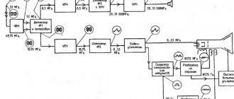
A single-line diagram is a simplified version of a schematic diagram, which leads to the emergence of its own reading features.
Checking the current transformer
A 25W, 8.5 Ohm carrying lamp and a digital voltmeter are connected to the CT as a load.
| Object included | Voltage, V |
| GW | 0,0 |
| FR | 0,0 |
| MK | 0,2 |
| 4 MV | 1,0 (1,1; 1,4) |
| 4 TED 300 A | 2,0 |
| 4 TED 600 A | 6,0 |
The voltage on the current coil closed by the meter is 0.034 V at a current of 5A (maximum load), that is, a difficult value to estimate.
Current transformer phase
Finding the counter and other elements on the diagram
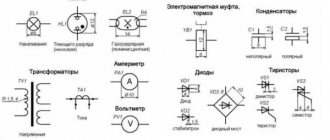
When examining the drawing, the specialist understands what is indicated by this or that sign. Uniform marking rules prevent misreading of the drawing, which is important when carrying out various works where contact with electrical energy is possible. Deciphering the diagrams seems difficult only at the beginning of studying the topic; if you have experience, finding an electric meter and other elements of interest will not be difficult. Some symbols are familiar to people from school physics lessons.
When considering the graphic designation of some elements, it is worth paying attention to the details. According to the number of rays in the socket, the number of inputs for plugs. The sockets themselves can be of several types, each of which has its own symbol:
- open-mounted socket;
- hidden socket (recessed into the wall);
- grounded socket;
- waterproof socket (for installation outdoors and in rooms with high humidity);
- three-phase socket.
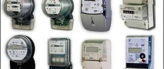
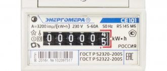
A meter is present in every diagram; not a single facility that consumes electricity can operate without a meter. The designation of the electric meter on the diagram is not so difficult to find. It is presented in the shape of a rectangle with a vertical stripe separating the top third of the figure, and the Wh symbols are present in the bottom two thirds. Knowing the floor plan helps in locating an electric meter; the meter is installed in places where it is easiest to take readings.
The counter doesn't work
- Compare meter readings in the log to determine the one whose readings have not changed during the trip, while the readings of other meters have changed. This is necessary to accurately determine what is faulty, since the team confuses not only the section, but even the electric locomotive during CME.
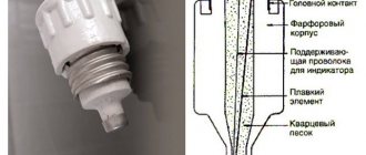
- Using an ohmmeter, check the resistance on the posts of glass fuse 122 on panel 1, with and without it. The first reading should be 0, the second 80-100 Ohms, that is, the integrity of the circuit passing through the auxiliary winding, the meter winding and fuse 131 (if it is on panel 2) is checked.
- Lightly pull the wire to the meter (4 pcs) to loosen the screws.
- Usually, after checking the fuses, remove and check the meter, since if it worked before, then the phasing is probably correct, and the current and wires rarely break.
- Unscrew the meter in place and check the markings. Phasing matters, that is, if you swap the current or voltage wires, the meter stops counting.
- If 2 current or network phasing wires are confused, it will not count, since the meter depends on the phase. True for F-442 with two LEDs
- If 2 wires, one from the current and the network, are tangled, then the network will be connected to ground and the RSC will immediately work, but there will be no short circuit and the meter will not burn out
- If 4 wires are tangled, the current ones are connected to the network and vice versa, then the internal current part of the meter circuit will create a short circuit and the fuses will burn out.
The need to read the electrical network diagram
A specialist can quickly find the required element using the icon. Such knowledge is required in various situations, such as repairing an existing electrical network, laying a new one, or installing electrical equipment. To install a new electric meter, you need to find the old one and replace it. On large objects, drawings are confusing, and you need to understand them in a short time. Quickly studying drawings is important in emergency situations.
Knowledge of symbols and skills in reading circuit diagrams or simplified single-line variants may be required for every person. Even a simple replacement of electrical wiring will force you to face difficulties without an understanding of basic things. Reading the drawing helps ensure safety during electrical installation work. Replacing a meter is a common operation, which is why knowing the designation of the meter in the diagram is so important.
Electricity meter designation on the diagram
Understanding electrical diagrams and drawings requires a certain level of knowledge. All elements of the electrical network have a conventional graphic designation that helps to clearly identify them. Knowing the meanings of symbols helps to read drawings of any complexity. The problem was the application of old standards, which were last updated a long time ago. Sometimes arbitrary designations of elements are used, but it is recommended to use icons from the standards to avoid double interpretations.
Normative base
There are a dozen types of electrical circuits, and the number of elements used is in the hundreds. Among this diversity, it is difficult for an untrained person to detect the meter designation, so compliance with uniform rules is important. The regulation of symbols in the electricity supply network is contained in the standards listed below:
- GOST 21.614 Symbolic graphic images of electrical equipment and wiring in the original
- GOST 2.273-68, GOST 2.279-68, GOST 2-755-87 Conventional graphic designations in diagrams (each of these standards covers its own area, 279 is devoted to current measuring instruments, and 755 to switching equipment)
- GOST 2-702-2011 ESKD. Rules for executing electrical circuits.
Low meter readings
Usually recording when there is a noticeable difference. It is better to compare the difference according to the readings in the magazine.
- Check that the current transformer is standard - TKLP-0.66. Another is allowed, but for correct calculation it must be with the parameter 300/5. Disconnect one wire, connect a resistance, for example 10 ohms, and a voltmeter to the current transmitter and check the voltage at the current transmitter at a certain load in the TED armature (see table below).
- Check the meter on the stand.
- If the type of current transformer is with 4 contacts, then connect it to the distantly located contacts. The closest ones are one plate.
| Current transformer parameters | |
| 0.66 kV | nom. voltage |
| 300/5 | 300 A - rated current in the power cable (primary winding) 5 A - rated current in the winding for the meter (secondary winding) This includes the transformation ratio, also indicated on the meter. |
| 10 VA | secondary winding power at rated current |
Finding the counter and other elements on the diagram
When examining the drawing, the specialist understands what is indicated by this or that sign. Uniform marking rules prevent misreading of the drawing, which is important when carrying out various works where contact with electrical energy is possible. Deciphering the diagrams seems difficult only at the beginning of studying the topic; if you have experience, finding an electric meter and other elements of interest will not be difficult. Some symbols are familiar to people from school physics lessons.
When considering the graphic designation of some elements, it is worth paying attention to the details. According to the number of rays in the socket, the number of inputs for plugs. The sockets themselves can be of several types, each of which has its own symbol:
- open-mounted socket
- hidden socket (recessed into the wall)
- grounded socket
- waterproof socket (for installation outdoors and in rooms with high humidity)
- three-phase socket.
A meter is present in every diagram; not a single facility that consumes electricity can operate without a meter. The designation of the electric meter on the diagram is not so difficult to find. It is presented in the shape of a rectangle with a vertical stripe separating the top third of the figure, and the Wh symbols are present in the bottom two thirds. Knowing the floor plan helps in locating an electric meter; the meter is installed in places where it is easiest to take readings.
A drawing with a large number of elements can drive an unprepared person into a stupor. Lamps and other lighting devices alone have 14 main designations. If replacement of lighting devices is required, the selection of equipment is carried out in accordance with the requirements of the drawing.
To quickly find the counter and other elements of interest, conventional graphic icons are learned by heart
In single-line and schematic diagrams, several groups that are most widespread can be distinguished:
- sockets
- switches
- lighting
- radioelements
- transformers
- electrical equipment.
Graphic icons are not the only way to represent elements; letter values are widely used. For the electricity meter, Pl is used; if there are several such elements in the network, a number is added (Pl1, Pl2, and so on). Devices are designated in Russian and Latin letters, so the presence of symbols from different alphabets in the drawing should not come as a surprise.
Marking
Marking of wires on the front side of the meter with contacts facing down:
| Wire marking | |||
| Current | Network 220 V | ||
| C6 | AND | 2S4 | C5 |
Marking of wires on the panel under the meter:
| Panel under the counter | |||||
| Uout | before | Iout | before | Uout | |
| C5 | S20 | C6 | AND | C9 | C4 |
| 1 | 2 | 3 | 4 | 5 | 6 |
| before | Uin | Iin | Uin | before | |
Marking on the unscrewed chip.
By the way, next to the chip there is a rail, where in the center is the current, the outer ones are the voltage (not always, see the marking).
The need to read the electrical network diagram
A specialist can quickly find the required element using the icon. Such knowledge is required in various situations, such as repairing an existing electrical network, laying a new one, or installing electrical equipment. To install a new electric meter, you need to find the old one and replace it. On large objects, drawings are confusing, and you need to understand them in a short time. Quickly studying drawings is important in emergency situations.
Knowledge of symbols and skills in reading circuit diagrams or simplified single-line variants may be required for every person. Even a simple replacement of electrical wiring will force you to face difficulties without an understanding of basic things. Reading the drawing helps ensure safety during electrical installation work. Replacing a meter is a common operation, which is why knowing the designation of the meter in the diagram is so important.
