In a previous article, I talked about how to check, find and troubleshoot brushed electric motors, which differ in that they have a brush-commutator assembly. Now I will tell you how to check, find faults and repair an asynchronous electric motor, which is the most reliable and easiest to manufacture of all types of motors. They are less common in everyday life (in a refrigerator compressor or in a washing machine), but they are often found in a garage or workshop: in machine tools, compressors, etc.
Repairing or testing an asynchronous electric motor with your own hands will not be difficult for most people. The most common failure of asynchronous motors is wear of the bearings, and less often, breakage or dampness of the windings.
Most faults can be identified by external inspection.
I recommend periodically , in order to extend the service life, check the condition of the electric motors: the condition of the bearings, clean the inside of it from debris and dust, and especially the ventilation holes.
Before connecting or if the motor has not been used for a long time, it is necessary to check its insulation resistance with a megger. Or if you don’t know an electrician with a megger, then it wouldn’t hurt to disassemble it for preventive purposes and dry the stator windings for several days.
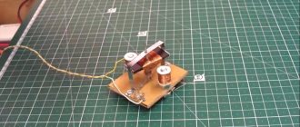
Before starting to repair the electric motor, it is necessary to check the presence of voltage and the serviceability of magnetic starters, thermal relays, connection cables and a capacitor, if present in the circuit.
Disassembling a typical asynchronous motor
Since there is a wide variety of designs of electric motors, to disassemble a particular electric motor you need to study its drawings and repair instructions, and watch visual videos.
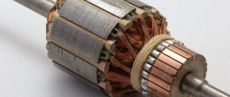
But in general terms, the designs of electric motors popular in everyday life are similar - there are rolling bearings on the rotor shaft, the outer races of which are pressed into seats on the inner surfaces of the end shields (covers).
Design of an asynchronous three-phase motor with a squirrel-cage rotor
The shields themselves are centered using a machined cylindrical edge that matches in size with the groove on the stator casing. The end shields are fixed using bolted connections. When disassembling the engine, its shaft is disconnected from the driven mechanisms and the electric motor is removed from the frame.
Removing the engine from the workplace
After this, it is necessary to remove the mechanical energy transmission element (pulley, gear, flange, etc.) from the shaft.
After unscrewing the fastening bolts, use a puller to remove the end shields from the bearings, after which you can carefully remove the rotor
Bearing puller
The bearings are cleaned, re-lubricated or replaced, the rotor and stator surfaces are cleaned, and the engine is reassembled. There are many bearing removal methods, methods and tools.
Normative documents
When operating, checking and servicing electric motors, you can use N.M.’s book as a guide. Slonim “Testing asynchronous motors during repairs,” which describes the methods for carrying them out. Despite its release in 1980, the book contains up-to-date information. Test methods for asynchronous motors are set out in GOST 7217-87, it is valid, the text was updated on 04/06/2015, reissued in 2003. In addition, the PUE and PTEEP also contain a testing program for AC electrical machines.
Also read:
- How to measure cable insulation resistance
- Checking the functionality of the circuit breaker
- What is phase rotation and how to check it
Published: 08/30/2019 Updated: 08/30/2019
Checking bearings and insulation
Bearing wear in an asynchronous motor is, in essence, the only parts that need to be replaced regularly. In powerful engines, the bearings are subject to large loads, leading to backlash and beating, which can be heard as quite loud noise when the rotor rotates. The rolling surfaces lose their original shape, and the cage begins to crack.
If the cage breaks during rotation, the rotor will no longer be coaxial with the stator and will snag on it. The consequences of such an accident will be very destructive for the engine and will most likely lead to its complete disrepair and impossibility of restoration. The condition of the bearings is determined by a special device based on noise level.
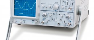
A very important and mandatory parameter to check is the state of the insulation of the wires and stator windings of the engine. To do this, you will need a special device - a megohmmeter.
Collector design
Collector models have also become very widespread. Their design features differ significantly when compared with asynchronous models. Checking the functionality when using a multimeter is carried out as follows:
- The tester is set to detect Ohm. The test begins with measuring the resistance on the collector lamellas. It is worth considering that normally the data obtained should not differ significantly.
- Next, the resistance indicator is measured, for which one probe of the device is applied to the armature body, the other to the commutator. The resulting resistance value should be high, approaching infinity. This indicates that the insulation is in good condition.
- The next step involves determining the stator for winding integrity. To do this, one probe is applied to the stator housing, and the other to the terminals. The higher the score, the better.
When using a multimeter, it will not be possible to check the turn-to-turn short circuit. A special apparatus is used for this.
Determination of the technical condition of the short-circuited rotor winding
- Connect one of the terminals of the phase winding, from the intercoil connection of which an additional terminal is made, and an additional terminal to the circuit to determine breaks in the rods of the short-circuited rotor windings.
- Apply an alternating current voltage of 10-15 V to the phase coil from the circuit.
- Slowly rotating the rotor until it makes one or one and a half turns, monitor the readings of the ammeter connected to the circuit of the phase winding coil, the terminals of which are energized. When the current changes, record its maximum and minimum values in a log. The constancy of the ammeter readings when turning the electric motor rotor indicates the absence of breaks in the short-circuited rotor winding rods. A change in current indicates the presence of a weakening of the cross-section or breakage of the rods.
Calculate the relative change in current using the formulaIf the relative change in current exceeds 15%, then the electric motor is disassembled and the number of broken rods is determined.
Note: If the electric motor is not adapted for diagnostics, then voltage is supplied to the phase winding. In this case, the permissible relative change in current when turning the rotor is 10%.
- Disconnect the motor winding from the circuit.
Testing the two-phase model
The stator and many other structural elements of a two-phase electric motor have their own distinctive features, which determine the features of the test.
The features of checking a two-phase electric motor include the following points:
- In this case, the resistance on the housing must be checked. A reading that is too low indicates that the stator needs to be rewinded.
- To obtain more accurate readings, it is recommended to use a megohmmeter, but such a measuring tool is extremely rare at home.
Before testing an electric motor, a visual inspection should be performed. Mechanical damage can lead to serious performance problems.
How to check the winding of an electric motor?
The next stage of testing is to check the motor winding for a short circuit to its housing. Most often, a household motor will not work with a closed winding, because the fuse will blow or the protection system will trip. The latter is typical for ungrounded devices designed for a voltage of 380 volts.
An ohmmeter is used to check resistance. You can use it to check the motor winding in this way:
- set the ohmmeter to resistance measurement mode;
- we connect the probes to the required sockets (usually to the common “Ohm” socket);
- select the scale with the highest multiplier (for example, R*1000, etc.);
- set the arrow to zero, and the probes should touch each other;
- we find a screw for grounding the electric motor (most often it has a hex head and is painted green). Instead of a screw, any metal part of the case can be used, on which the paint can be scraped off for better contact with the metal;
- We press the ohmmeter probe to this place, and press the second probe in turn to each electrical contact of the engine;
- Ideally, the meter needle should deviate slightly from the highest resistance reading.
While working, make sure that your hands do not touch the probes, otherwise the readings will be incorrect. The resistance value should be shown in millions of ohms or megohms. If you have a digital ohmmeter, some of them do not have the ability to set the device to zero; for such ohmmeters, the zeroing step should be skipped.
Also, when checking the windings, make sure that they are not short-circuited or broken. Some simple single-phase or three-phase electric motors are tested by switching the ohmmeter to the lowest range, then setting the needle to zero and measuring the resistance between the wires.
To make sure that each of the windings is measured, you need to refer to the motor diagram.
If the ohmmeter shows a very low resistance value, it means that it either exists, or you touched the probes of the device. And if the value is too high, then this indicates problems with the motor windings. for example, about a breakup. If the resistance of the windings is high, the entire motor will not work, or its speed controller will fail. The latter most often concerns three-phase motors.
Multimeter selection criteria
Multimeters are used to test various electrical equipment. On sale you can find various versions of this measuring device, they all have their own characteristics. The main selection criteria are the following:
- Pointer or digital dial. Digital is more in demand today, as it has a large number of different functions and high accuracy. Today, switch models are practically not found on sale.
- Functionality. The more functions, the wider the scope of application of the device. This increases the cost of the measuring device.
- The backlight and hold button for readings can improve the comfort of using the multimeter.
- The lower the operating error, the more accurate the tester. Most models have an error of no more than 3%.
- If professional provision of services is envisaged, then attention should be paid to a model with a high degree of protection from dust or moisture. The higher the degree of protection of the device, the longer it will last.
- Electrical safety class. All measuring instruments are divided into 4 classes, which determine the scope of application of the multimeter.
You can check the basic indicators of an electric motor using the simplest equipment.
Basic malfunctions of three-phase asynchronous electric motors and ways to eliminate them
Basic malfunctions of three-phase asynchronous electric motors and ways to eliminate them
Malfunctions of windings of asynchronous electric motors and ways to eliminate them
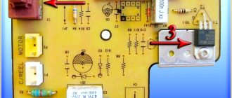
Short to body. If the winding is short-circuited to the housing, you need to check the electric motor with a test lamp powered from the mains (Fig. 31).
In some cases, it is advisable to open the winding at several points and check it in parts. First tested
each phase separately (Fig. 32), and then the pole-phase winding groups (Fig. 33).
Short circuit of turns. In this case, several turns or the coil as a whole are closed. The first way to find damage: determine overheating of the frontal parts of the winding by touch. The second method: the winding is fed with alternating current of high frequency (up to 400 Hz) and a piece of steel is applied to the stator core along the entire circumference. The place of damage is under the pole, where the steel is weakly attracted.
A short circuit of the pole-phase group is usually determined using a compass moved around the circumference of the stator
If the windings are connected by a star, then the positive pole of the current source is connected to the terminals in turn, and the negative pole is connected to the zero point of the winding.
The same method can also detect the inverted phase of the winding.
When connecting the winding with a triangle, you need to open one of the vertices of the triangle, to which direct current is supplied.
A short circuit of most of the phase winding is determined by measuring the undervoltage current or the phase resistance of the windings (Fig. 35). An increased current in one of the phases and a decreased resistance indicate the presence of a short circuit (Fig. 36).
Flail break. Typical and common breaks occur when the connection of the winding conductors is broken. If the winding is connected in a star and does not have parallel branches, then a winding phase failure is easily detected by a test lamp connected according to the diagram in Figure 37.
If the winding is connected in a triangle (without parallel branches), then it is opened and each phase is checked separately with a test lamp.
For electric motors with parallel winding branches, the damaged phase is determined by measuring currents in individual phases. Subsequently, the damaged phase is divided into parallel branches, which are studied separately.
Technical data of DC electric motors type MP
To leave a comment, please register or log in to the site.
Design features
The design of electric motors can differ significantly, but it is often represented by a combination of similar elements. The moving element is usually called the rotor, the stationary element is called the starter. Copper wire can be wound as follows:
- The coil is only on the rotor.
- The coil is only on the starter.
- Winding on moving and stationary parts.
Types of electrical machine repairs
To prevent malfunctions, maintenance and scheduled repairs of electrical equipment should be carried out according to the approved schedule.
Electrical machine repairs are divided into maintenance (MOT), current, medium and major repairs. The scope of work in each of these types of work is determined by the “Standard Regulations on Maintenance and Repair (MRO) of Electrical Equipment”.
Maintenance
This is to maintain equipment in working order between scheduled repairs. Carried out by maintenance and operational maintenance personnel.
Provides for the following types of work:
- inspection;
- heating check;
- wiping off dirt;
- insulation check;
- identifying faults and eliminating them.
It is carried out according to the approved schedule and during downtime - lunch break, adjustment, tool change.
Maintenance
Maintained in working condition until repaired. Produced on site or in a workshop. Includes:
- complex of maintenance works;
- replacement of failed components - bearings and couplings;
- adjustment and checking of alignment.
Medium renovation
For problems that cannot be eliminated during routine repairs, a medium repair is performed. This produces:
- complete disassembly;
- if necessary, replace bearings;
- repair of housing and shaft;
- impregnation of windings with varnish;
- insulation or replacement of leads
Medium repairs are carried out in specialized workshops and enterprises.
Major renovation
Complete restoration of characteristics and parameters. In addition to the complex of medium repair works, the windings of the electric machine are replaced or repaired.
Electric motor malfunctions are easier to prevent than to eliminate their consequences. To do this, it is necessary to carry out a set of work on servicing the mechanism in a timely manner and equip it with the necessary protective devices.
{SOURCE}
Reasons for failure of electric motors
All faults can be divided into two groups - failure as a result of improper transportation or storage and breakdowns that appeared during operation.
Improper transportation and storage
The main problem that appears during this period is increased humidity, and even more so when the electric machine gets caught in the rain. This leads to a breakdown of the insulation, and in more severe cases, to the appearance of rust inside the device and bearings.
Therefore, before installing such a device, it is necessary to carry out routine repairs and eliminate the detected problems:
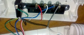
- carry out an external inspection of the machine, insulation on the terminals and internal jumpers;
- check the insulation condition with a megger;
- check the presence of lubrication and the condition of the bearings;
- in commutator motors of direct and alternating current, as well as in asynchronous machines with a wound rotor, the condition of the commutator or slip rings and brushes is determined.
All these operations are carried out in a warehouse or workshop near the site of future installation. If it is impossible to eliminate the problems, the electric machine is sent to a specialized enterprise for medium repairs.
Reasons for failure during operation
During operation, the main reasons for failure of an electric machine are:
- Mechanical wear of bearings. This occurs throughout the entire service life, as well as due to increased vibration and irregular lubricant changes. To prevent such situations, it is necessary to carry out full maintenance of all components and mechanisms. Failure to correct the malfunction in a timely manner leads to increased engine vibration, overheating of the bearing shields, wear of the bearing seats and jamming of the rotor.
- Destruction of the housing, bolts and bearing seats. Occurs due to increased vibration of the gearbox and poor alignment of the electric motor. The electric drive must be removed or replaced immediately. The consequences are similar to bearing failure.
- Motor overload and operation of three-phase devices in two phases. Correctly configured thermal relays protect against this. If there is no protection, the device will overheat above the maximum permissible temperature, which will lead to failure of the electric machine.
Reference! New electric motors are equipped with a temperature sensor that turns off the mechanism when the device overheats. It can also be additionally installed in the engine of an older model.
Standards for testing electrical machines after repair (according to PEEP)
Random stator windings
Table 4
| AC motor element under test with Un≤0.66 kV | Test voltage, kV depending on power Pn, kW | |
| 0,2…10 | 10,1…1000 | |
| Windings after laying in the grooves before soldering the intercoil connections | 2,5 | 3,0 |
| Windings after soldering and insulating intercoil connections | 2,3 | 2,7 |
| Windings after impregnation and pressing of the wound core | 2,2 | 2,5 |
| Main winding insulation of assembled AC motor | 2Un+1.0, but not less than 1.5 |
Rectangular wire stator windings
Table 5
| Test voltage for | ||||||||
| Test element | electric motors for rated voltage, kV | |||||||
| motor windings | up to 1000 kW | over 1000 kW | ||||||
| up to 0.66 | 2 | 3 | 6 | 10 | 3 | 6 | 10 | |
| Separate coil | 4,5 | 11,0 | 13,5 | 21,1 | 31,5 | 13,5 | 23,5 | 34,0 |
| (rod) before laying | ||||||||
| Winding after laying | 3,5 | 9,0 | 11,5 | 18,5 | 29,0 | 11,5 | 20,5 | 30,0 |
| into the grooves before soldering between | ||||||||
| coil connections | ||||||||
| Windings after soldering | 3,0 | 6,5 | 9,0 | 15,8 | 25,0 | 9,0 | 18.5 | 27,0 |
| and insulation of connections | ||||||||
| Main winding insulation of the assembled machine | 2Un+1 | 5,0 | 7,0 | 13,0 | 21,0 | 7,0 | 15.0 | 23.0 |
| but not | ||||||||
| <1.5kV |
Rotor windings
Table 6
| Test element of the rotor of asynchronous motors | Test voltage, kV |
| 1. Complete winding replacement | |
| Individual rods before placement into grooves Rods after laying in grooves, but before joining Winding after connection, soldering and banding Slip rings before connection to the winding | 2U*mouth+3.0 2U*mouth+2.0 2U*mouth+1.0 2U*mouth+2.2 |
| 2. Partial winding replacement | |
| The remainder of the winding after removing the replacement coils, sections or bars | 2U*mouth (but not less than 1.2 kV) |
| The entire winding after attaching new coils, sections or rods | 2U*mouth (but not less than 1.0 kV) |
* 2U*rot - voltage on the rings of a stationary rotor with an open winding at the rated voltage on the stator.
Permissible air gap values
Table 7
| Nominal shaft diameter, mm | Gap, microns. at rotation speed, rpm | ||
| up to 1000 | 1000… 1500 | more than 1500 | |
| 18. ..30 | 40 …93 | 60… 130 | 140 …280 |
| 31. ..50 | 50… 112 | 75… 160 | 170. ..340 |
| 51 …80 | 65… 135 | 95… 195 | 200 …400 |
| 81 … 120 | 80… 160 | 120. ..235 | 230 …460 |
| 121 … 180 | 100… 195 | 150. ..285 | 260 …530 |
| 181 …260 | 120 …225 | 180. ..300 | 300 …600 |
| 261 …360 | 140 …250 | 210. ..380 | 340 …680 |
| 361 …600 | 170 …305 | 250. ..440 | 380 …760 |
Table 8
| Turns insulation type | Voltage amplitude, V/turn | |
| before laying the sections in the grooves | after laying and bandaging | |
| Air defense wire | 210 | 180 |
| Wires PBD, PDA, PSD | 420 | 360 |
| PBD wire with single layer paper tape insulation | 700 | 600 |
| PBD and PDA wires with insulation layer micalent through a coil | 700 | 600 |
| The same, with micanite spacers in the groove part between turns | 1000 | 850 |
| Wire with single-layer insulation with mica tape 0.13 mm thick with full overlap | 1100 | 950 |
| PBB wire with single-layer silk varnish insulation 0.1 mm thick with full overlap | 1400 | 1200 |
| PBD and PDA wires with single-layer insulation with mica tape 0.13 mm thick with a full overlap or 1/3 overlap | 1400 | 1200 |
| PBB or PDA wire with single-layer insulation with mica tape 0.13 mm thick, completely overlapped and topped with a layer of cotton tape end-to-end | 2100 | 1800 |
| PDA wire, insulated with two layers of mycalente 0.13 mm thick, completely overlapping | 2800 | 2400 |
conclusions
Today, there are already many methods for diagnosing the condition of an asynchronous motor during its operation. All of them are still being improved, which confirms their relevance and practical performance.
In this work, the most well-known of them were considered, and it was highlighted that the most promising methods for practical implementation are methods for diagnosing an asynchronous motor, based on the analysis of the electrical parameters of the motor, namely the spectra of voltages and currents. There is also a requirement for the sampling frequency of measuring channels for this method.
Further research is aimed at the following aspects:
- Selection of the optimal structure of the circuit for the practical implementation of the diagnostic method for an asynchronous motor;
- Calculation and selection of necessary equipment;
- Presentation of a working diagram for the practical implementation of diagnostics of an asynchronous motor during its operation.
At the time of writing this essay, the master's thesis has not yet been completed. Estimated completion date for the master's thesis: June 2022. Full text of the work and
Introduction
Domestic and foreign experience shows that the introduction of diagnostic tools is one of the most important factors in increasing the economic efficiency of using equipment in industry []. The purpose of diagnostics is to identify and prevent failures and malfunctions, maintain operational performance within established limits, predict the condition in order to fully utilize the resource [].
Squirrel-cage asynchronous electric motors are the most common machines in modern drive technologies. The optimal use of such electric motors is hampered by their high level of damage. Every year, 20–25% of the total number of installed electric motors fail []. The resulting damage is associated with downtime of technological equipment due to an engine failure. In addition to direct losses, there is a decrease in electrical and fire safety, which is associated with short circuits that may be present in the stator or rotor winding of a damaged electric motor [].
Thus, the tasks of reducing the level of direct and indirect costs during the operation of asynchronous motors, improving the quality of their diagnostics, as well as increasing their reliability are relevant today in any industry. The most widely used general industrial asynchronous motors of medium power (from 1 to 4000 kW) are considered as objects of research in the article.