In order for grounding to function properly, the resistance of its conductors should not be higher than 4 Ohms, and it is necessary to regularly monitor that this indicator does not increase. Next, we'll figure out how to test the grounding to determine whether the protection is capable of functioning effectively. Let's consider what instruments are needed for this, how often it is necessary to check, and what minimum theoretical knowledge is needed for this work.
Measuring ground loop resistance Source gradusplus.com
Basics of functioning of grounding systems
Potential may accumulate on the housings of some electrical devices (with high conductivity, for example, metal) due to the ingress of current in the event of a breakdown of the insulating layer of the wiring. If there is such a malfunction, any touch to the body of the device is fraught with the passage of current from the device to the “ground” through the person (from the hand and then along the body and leg to the “ground”). Under unfavorable circumstances, this can lead to death, because Only 100 mA is enough for the damaging processes from an electric shock in the human body to lead to irreversible consequences.
As you know, electric current tends to pass through conductors with the lowest resistance. This property serves as the basis for the functioning of any protective grounding system. In essence, grounding is the connection of metal parts of electrical installations with a conductor of maximum capacity and minimum resistance, which reliably protects a person from electric shock if it hits the device body.
The human body, consisting mainly of water, is considered a good conductor with a nominal resistance of 1000 Ohms. Calculations show that electric current will “pass by” a person if it flows through a conductor with a significantly lower resistance, which does not exceed 4 Ohms and 8 Ohms - at a voltage in the circuit of 380V and 220V, respectively. It is these values that are indicated in the PUE and you need to focus on them.
Regular testing and measuring of grounding, discussed below, can prevent possible negative consequences in advance.
Schematic representation of the grounding system for almost any household appliance Source gradusplus.com
The power cable of any modern electrical device contains a special wire that connects the device body to a separate contact on the plug. When this plug is inserted into an outlet, this pin makes contact with the grounding terminal of the outlet, and therefore with the entire grounding of the structure.
If, due to damage to the wiring, an electric current leaks, the latter will go into the ground through the grounding wiring, which has minimal resistance. For this protection to work properly, resistance indicators are of key importance, monitoring which makes it possible to prevent and prevent possible accidents.
Useful tips and general recommendations
When carrying out major repairs with replacement of electrical wiring, it is necessary to install a grounding line. Do not allow equipment housings to be connected to central heating or water supply pipes.
In addition to the risk of electric shock to residents, the wear of metal lines located in the basement and ground accelerates in neighboring apartments. Electrochemical corrosion causes the formation of small cracks (fistulas) on the surface of pipes and on welds.
When rewiring electrical wiring, install an RCD unit in addition to the ground line. The device detects current leakage and breaks the circuit.
Due to the increased speed of the RCD, it minimizes the risk of electric shock to a person. In the event of a phase short circuit to the housing, the potential goes to ground, the device opens the circuit, providing additional protection and indicating the presence of a fault in the power line.
The need for regular checks
The need to maintain the serviceability of the ground loop is considered a prerequisite for the effective functioning of the system. Therefore, a periodic grounding test with a multimeter (as the most accessible tester for the average person) is needed, the results of which will determine the performance of the circuit.
If the grounding is in normal working order, any emergency situation that arises will lead to the discharge of electric current through the grounding conductor into current-carrying elements located in the ground, from which the electric discharge will quickly and uniformly spread deep into the soil.
Grounding diagram for a private house Source sovet-ingenera.com
See also: Catalog of companies that specialize in electrical work of any complexity
The reliability of any electrical circuit is inversely proportional to the number of conductor connections - the fewer, the better. But in any case, it is impossible to get rid of them completely. In addition, it must be taken into account that some of the connections are in the ground and from prolonged contact with it, an oxide layer is formed on the metal of the current-carrying electrodes, leading to the inevitable formation of a corrosion layer.
The result may be an increase in the resistance of the device elements and the occurrence of obstacles to the flow of current. Plus, the presence of any substance with increased chemical activity in the area of soil that includes grounding leads to the fastest possible occurrence of rust, since the metal parts of the circuit constantly interact with the soil.
Over time, corrosion leads to the formation of individual flakes that begin the process of peeling away from the metal, thereby deteriorating the electrical contact. Because of this, the circuit resistance increases, because the number of these corroded areas becomes large. The grounding device loses electrical conductivity, the likelihood of incomplete discharge of electric currents into the soil increases, and the overall level of protection decreases.
As a result, the inspection usually begins with an assessment of the technical condition of the circuit and its components.
An example of corrosion of a grounding device Source gidpokraske.ru
Measuring the ground loop resistance makes it possible to verify the safety of the system. Technically, this calculation of resistance is based on Ohm’s law, known to everyone from the school physics course. If the voltage and current in the current source are known, or we can measure it, then it is enough to simply determine the resistance by dividing the voltage by the current. But the practice is somewhat more complicated and has a number of features and measurement rules that require their strict implementation.
Factors affecting ground resistance
The first thing that affects ground resistance is the type of soil. Depending on the percentage of clay, black soil or gravel, the resistance value also changes. Experts use appropriate tables that take this parameter into account.
Another important point is soil moisture. The larger it is, the less it resists electric current. Soil temperature also affects conductivity. Therefore, the ground loop pins must be driven as deep as possible in order to eliminate this influence factor as much as possible.
Taking into account the above, grounding measurements should be carried out during the period of greatest soil stability. In central Russia it is mid-summer. In spring, autumn or winter, precipitation and low temperatures can distort the indicators. For safety reasons, it is prohibited to measure ground resistance during a thunderstorm. Ideally, the resistance should be zero. Although some minimal deviation is not critical.
We figured out what grounding is. Now let's move on to how to measure ground resistance with a multimeter. Let's start with a review of the device itself.
Professional measurement (using a megohmmeter)
The generally accepted grounding measurement includes the following sequence of actions:
- Visual inspection of connections on bolts and welded contacts should be carried out;
- take resistance readings of the entire circuit;
- check the resistivity of the soil layer.
Measurements are carried out using special instruments. The megohmmeter that is best suited for this is considered optimal.
Megaohmmeter – model M-416 Source pribor-service.ru
Testing of residual current device
If there is an RCD in the distribution board, before checking the ground loop with a multimeter, it makes sense to make sure that the protection is working. If the home technician does not trust the “test” button, you can conduct your own tests. To do this, the RCD is completely disconnected from the network, and pieces of wire are connected to its input and output contacts (one of two). For example, let's take the upper and lower phase terminals. The flag is turned to the “On” position, after which a regular 1.5 V battery is connected to the free ends. The field created on one coil and its absence on the second creates the appearance of a leak, as a result of which a cutoff should occur. If this does not happen, the device is faulty.
Video description
Briefly about the theory and practice of using ohmmeters M-416 and M-4001 is described in this video:
- The rod of the probe and the accessory electrode are driven into the soil to a depth of over half a meter. This is done on soil with natural density (not poured or loosened) by hammering it in with a sledgehammer.
- At the junction of the grounding wire and the electrode, it is important to clean off the remaining paint coating. Copper wires with a cross-sectional area of 1.5 mm² are used.
- It is recommended to begin direct work on measuring the resistance of protective devices by selecting the “x1” range. After pressing the red button, the handle of the device rotates until the arrow reaches the zero mark. Higher resistance values should be measured by choosing larger ranges - “x5” or “x20”. For measuring the resistance of the protective circuit, the indicator “x1” is used, which is sufficient to display the results on the instrument scale.
It is optimal to carry out such measurements in the most dense soil and in dry summer weather conditions. You can make the same measurements in winter, but it is recommended to do this during frosts, when the soil is frozen as much as possible. It is not advisable to take measurements in wet weather, because... the data obtained will be greatly distorted and therefore unreliable.
Checking grounding with an electronic megohmmeter Source uk-parkovaya.ru
Typical socket design
Using the socket grounding test technique may be necessary at any time. Especially for those people who will have to work with specific electrical outlets repeatedly.
This part of the electrical network (domestic or industrial) has a simple design.
The electrical outlet does not shine with design difficulties. A simple ceramic or plastic base plus a metal frame with a lid. Still, electrical outlets are improving.
The electrical outlet consists of a round or rectangular plate. The plateau is made from materials that do not conduct electricity.
Typically, the following is used to make socket plates:
- ceramics;
- porcelain;
- plastic.
The back of the plateau has a flat surface, and on the front there are shaped landing pads for electrical contactors. The material of contactors is usually copper. The contactors are fixed to the plateau rigidly - using rivets, plus they are embedded in the body of the plateau.
For connection to electrical wiring, the contactors have mounting screws. This entire structure is closed with a lid that has two passage holes for an electrical plug.
Checking grounding in a home network (using a multimeter)
As a rule, in new housing, the electrical network has already been wired, so you need to know how to check the grounding resistance of already installed household outlets.
This work should also begin with a visual inspection of the item being measured. You should turn off the power and remove the protective cover of any of the sockets that are equipped with a special terminal for connecting the ground loop conductor (usually a yellow-green wire). If only two wires are connected to the contacts (phase and neutral, usually brown and blue, respectively), then this clearly indicates the absence of grounding.
If the third wire is still present, this does not guarantee its proper functioning. It is necessary to carry out a special test procedure with a multimeter. The sequence is as follows:
- The input circuit breaker is turned on so that there is voltage in the network (sockets).
- The tester switches to voltage measurement mode - usually this is the “ACV” icon.
How to understand that the ground loop is not working?
It is not necessary to measure the voltage with a multimeter to identify problems in the operation of the ground loop. The appearance of noise in the speakers, discharges of current from the washing machine indicate that electricity is not going into the ground. If you have old heating radiators installed in your home, then a large amount of dust will accumulate near them.
If you are unable to measure the voltage of the ground loop yourself, then invite an electrician. With small differences, problems with the operation of this electrical connection are invisible, but if a serious short circuit occurs, the person in contact with the equipment may die, because current will flow into it.
Video description
This short video shows how to check the grounding of a socket using a multimeter:
- The probes of the device are applied to the contacts, and the voltage between the phase and neutral wires is measured. For a home network it should be standard 220V.
- Similar measurements are made with a multimeter with phase and ground - the result should be approximately the same as in the previous measurement. If the instrument scale shows a lower voltage reading, it means the grounding is not working well. If the device does not respond when the probes touch the contacts, it means that the ground loop is not connected or is faulty.
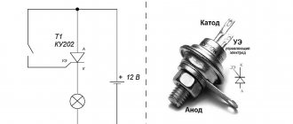
Even when there are no measuring instruments in the house, it is possible to check using available means. You will need a homemade device in the form of a light bulb screwed into a socket, from which extend pieces of wire with stripped contacts at the ends. People call it “control”. Such a device is sometimes used by self-taught electricians (and not only), but, as a rule, its use is not recommended by professionals.
To check, one contact of the “tester” is in contact with the phase, and the second is in contact with zero. When the light comes on, it indicates the presence of voltage. Then the contact from zero is moved to the ground wire. The operation of the light indicates the presence of a working protective system. A weak or intermittent glow indicates problems in the circuit, and a complete absence of light indicates its complete malfunction.
Appearance of the panel of the most common electronic multimeter with explanations for use Source lifehacker.ru
Types of electrical outlets
The industry produces two types of products:
- equipped with a grounding bus;
- not having a grounding bus.
The first type of design is often called a “euro-socket”. This design fully satisfies electrical safety requirements. When changing electrical wiring, it is recommended to install sockets with grounding.
The appearance of the electrical outlet according to the standards established by the European Union countries. A distinctive feature of the design is the presence of contact bimetallic grounding plates
The second type of product is considered an outdated modification, but is still found in practice. Especially many outdated sockets are used in old buildings.
Design option without specific country affiliation. For modern electricians, it is considered an outdated model, which is not recommended for installation due to increased danger due to the lack of a grounding contactor
Both types of products are made for indoor or outdoor installation. According to the new PEB recommendations, modifications of sockets for internal installation must have bimetallic plates with a grounding contactor as part of the design.
For electrical sockets for external installation, the recommendations are the same, but in some cases of their use a two-wire interface is allowed.
Briefly about the main thing
The resistance of a properly functioning grounding should be 4 Ohms. Since the resistance at the conductor connections may increase over time, the grounding must be checked regularly - approximately every 12 months.
There are several ways to measure the grounding resistance of a home network. Professionals carry out this work using a device such as a megohmmeter. At home, you can use a standard multimeter or even a homemade “control”, but you need some experience to correctly interpret their readings.
In general, tests are based on Ohm's law - the voltage in the circuit and the current are checked and the resistance is calculated from them. The measurement procedure is quite simple and can be done by the average person if he knows the basics of working with electricity and electrical safety rules. If you have doubts about your skills, it is recommended to seek the services of specialists.
Indirect evidence of the absence of PE
There are some situations that indirectly confirm that the PE circuit is not working, is not connected or is working very poorly.
- Household appliances connected to water give a slight electric shock. These include a washing machine, dishwasher, water heater, electric kettle and others.
- There is noise in the speakers when playing music.
These are the simple ways to determine whether a wired PE system is working or not. And one more warning. It cannot be connected to a lightning rod or used for heating. Neither system is designed for these needs.
If you find an error, please select a piece of text and press Ctrl+Enter.