A thyristor is a semiconductor device with a pnpn structure that plays the role of a switch in circuits with high currents, while it is controlled by a low-current signal. It is used to switch on power electric drives and generator excitation systems. Switched currents reach up to 10 kA.
The peculiarity of thyristors is that when a control signal is applied, they open and remain in this state, even if the signal is subsequently removed. The only requirement is that the current flowing through them must exceed a certain value, which is called the holding current.
Some thyristors only allow current to flow in one direction. These are dinistors that are triggered when a significant voltage is exceeded. There are also SCRs controlled by supplying current to the third terminal of the device.
Thyristors that pass current in both directions are called triacs or triacs. In addition, there are photothyristors controlled by light.
Main characteristics
To check the SCR, you need to know and understand what is hidden behind the main parameters and why they need to be measured.
The control unlocking voltage Uy is a constant potential on the control electrode, causing the thyristor to open.
Urev max is the maximum reverse voltage at which the thyristor is still in working condition.
Ioc cp is the average value of the current flowing through the thyristor in the forward direction while maintaining its operability.
Products :: Oreltekhpribor LLC
Our production
1. Temperature regulators with a thermal switch (PTR, TAB-T), are designed to regulate the operation of the evaporator defrost system (temperature control function) and for emergency opening of the electrical circuit of the NO-FROST system heaters in the event of a malfunction of the circuit elements (thermal switch function) in household refrigerators - freezers Stinol, Indesit, Ariston, Pozis, etc.
The devices also have designs designed only for emergency opening of the electrical circuit (thermal switches).
2. Electronic timers (TIM-01), designed for automatic control of the defrosting mode in the system
NO-FROST.
Parameters of manufactured appliances for household refrigerators with the NO-FROST system
1. Regulator PTR-101, TAB-T (3 wires, with block, instead of TAB-T-19)
2. Regulator PTR-102, TAB-T (3 wires, without block, instead of TAB-T-20)
3. Regulator PTR-103, TAB-T (2 wires, with block, instead of TAB-T-21)
4. Thermal switch PTR-201, TAB-T-18 (4 wires, with block)
5. Regulator TAB-T-2, TAB-1-MK (4 separate wires)
6. TAB-T-4 regulator (3 separate wires)
7. Thermal switch TAB-T-17 (2 wires, 1 fuse link)
8. Electronic timer TIM-01 (instead of TEU-01-2.3 and TEO-02)
Options for manufactured timers:
1. TIM-01-11 (activation of defrost mode after 8 hours, initial activation - refrigeration mode)
2. TIM-01-S (activation of defrost mode after 8 hours, initial activation – passive defrost mode 2...3 min).
Thank you for your interest in us.
proizvodstvo-priborov.webnode.ru
Determination of control voltage
Now you can start testing the SCR. To do this, let's take KU202N with an operating current of 10 A and a voltage of 400 V.
Most radio amateurs have a multimeter and the question inevitably arises of how to check a thyristor with a multimeter, whether this is possible and what additional things may be needed. The sequence of actions is as follows:
First, switch the multimeter to the resistance measurement position with a range of 2 kOhm. In this mode, the voltage of the tester's internal power supply will be present on the test leads;- We connect the probes to the anode and cathode of the SCR. The multimeter should show a resistance close to infinity;
- We connect the anode and the control electrode with a jumper. The resistance should drop, the SCR has opened;
- We remove the jumper, the device again shows infinity. This is due to the holding current being too low.
Since the thyristor is controlled by both negative and positive signals, it can be opened by connecting the control electrode to the cathode with a jumper.
The multimeter should be in ohmmeter mode and the probes connected to the anode and cathode. This way you can determine what voltage the thyristor is controlled by.
High voltage thyristor testing
If you are testing a high-voltage thyristor, you will need a multimeter with a current clamp. And the check will be carried out with the equipment turned on, since it is difficult to create conditions that simulate the operating parameters of the system.
All external influences must be done in accordance with the operating instructions for the equipment.
Measurements are made in compliance with safety precautions, otherwise everything is the same as with conventional thyristors.
Thyristors belong to the class of diodes. But in addition to the anode and cathode, thyristors have a third output - a control electrode.
A thyristor is a kind of electronic switch consisting of four layers, which can be in two states:
- High conductivity (open).
- Low conductivity (closed).
Thyristors have high power, due to which they switch circuits at voltages reaching up to 5 thousand volts and with a current equal to 5 thousand amperes. Such switches can only conduct current in the forward direction, and in a state of low conductivity they can even withstand reverse voltage.
There are different thyristors that differ from each other in characteristics, control, etc.
The most famous types of these devices:
- Diode. Enters conducting mode when current level increases.
- Inverter. It switches to low conductivity mode faster than similar devices.
- Symmetric. The device is similar to 2 devices with back-to-back diodes.
- Optothyristor. It works thanks to the flow of light.
- Lockable.
Functionality check
The second testing option is as follows. A lamp at the same voltage is connected to the DC power supply through a thyristor.
A multimeter is connected to the anode and cathode in DC voltage measurement mode. The measurement range must be greater than the source voltage.
Then, control voltage is supplied to the control electrode using a battery of any rating and a pair of wires. The thyristor should open and the light should light up.
The tester first shows the voltage of the power source, after exposure to a small value, which corresponds to the potential drop across the thyristor in the open state.
After this, you can remove the control action, the lamp will continue to burn, since the current flowing through the device is greater than the holding current.
No Frost system in Indesit and Ariston refrigerators SW19.ru
Let's consider refrigerators from Indesit and Ariston with the “no frost” system.
Which translated into Russian means “no frost.” A special feature of this series of refrigerators is the presence of a forced evaporator defrost system. For this purpose, there is a heating element next to the evaporator, which turns on at intervals set by the defrost timer. The defrost timer itself, for some reason, is located near the evaporator, which is not entirely correct from an engineering point of view. But on the other hand, this arrangement increases the degree of fire protection of the refrigerator. In Indesit refrigerators of this series there are many types of interchangeable timers from different manufacturers. The popularity of their production apparently grew due to their fragility. With the transition from mechanical timers to electronic ones, the latter inherited the connection system from the former as a standard. In other words, the old mechanical timer will take root in the new refrigerator. Let's consider the refrigerator operation system based on the popular TIM-01 timer, paired with a TAB-T-1 thermal switch. Most failures in the operation of refrigerators in this series occur in the defrosting system. The lower figure shows the electrical diagram of refrigerators with the “no frost” system.
For clarity, I simplified the diagram, leaving only the main elements. This will make it easier to understand the operating principle.
The initial position of the system in the diagram corresponds to the temperature in the refrigerator chambers of +20 C. Or we can say that the refrigerator has not been turned on for a long time. We fall into the power supply system, for which we move the thermostat to the extreme right position. The voltage comes to the compressor motor (MC) through the closed contacts of the thermostat. Another potential powers the motor through normally closed contacts 2 and 3 of the TIM-01 timer. The compressor begins to force refrigerant into the system. At this stage, you will not be able to check the defrosting system using the TIM-01 relay test button. The reason for this is very simple; at this moment there is no power to the relay itself. After about 10-15 minutes, the temperature on the evaporator will drop to the desired 8 degrees. The TAB-T-1 relay will close its contacts and, through the heating element, supply power to the TIM-01 timer. The timer will begin to count down the compressor operating time. Here you can already start a forced defrost cycle from the test button of the TIM-01 relay. If the coil of the heating element is broken, then voltage will not appear on the timer, and accordingly, the forced test of the defrost system will not turn on. When the test starts, the timer will switch its contacts, cut off the power supply to the compressor and close the group of contacts 3 and 4, supplying power to the evaporator heating element. At this moment, the TIM-01 relay itself is powered through the compressor motor winding and continues to keep the heating element energized. When the evaporator temperature reaches +11 degrees, the thermal relay TAB-T-1 opens again. Timer TIM-01 through 1 contact detects the opening of the thermal switch contacts and moves to the initial position. The compressor turns on again and the freezing cycle begins. During the operating cycle, the timer waits 2 minutes between turning off the heater and turning on the compressor. In a continuous operating cycle, the timer constantly counts the operating time of the compressor. It cannot count the idle time, since when the thermostat contacts are open, no power is supplied to it. During pauses in compressor operation, the timer stores its readings in memory. Then, when power appears, it reads the stored values again and continues to count the compressor operating time. Every 8 hours of compressor operation, the timer switches to evaporator defrost mode. The second contacts in the TAB-T-1 thermal relay are emergency and are triggered when the evaporator chamber overheats above 72 degrees. After the emergency contacts are triggered, the TAB-T-1 thermal relay is not restored and becomes unsuitable for further use. Using the same scheme as shown above, a small test stand is assembled to test the defrost timer operation cycles.
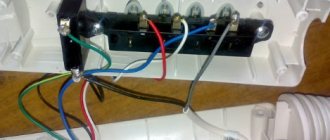
The role of the heating element and the compressor motor is performed by two 40-watt incandescent lamps with E-14 sockets. The contact block for the timer is made from standard terminals, located in the correct position and filled with compound. The operation of a thermal relay is simulated using a conventional switch. The thermostat, if necessary, is simulated by disconnecting the power plug of the device. The advantage here is that checking the timer on the stand is done quite quickly, unlike checking on the refrigerator itself. Which significantly saves the technician’s precious time. “No frost” refrigerators from Indesit and Ariston can be equipped with other timers and thermal relays. However, the principle of operation of the entire system remains the same.
sw19.ru
Checking the dinistor
To determine the performance of the dinistor, a power source with a voltage higher than the turn-on voltage of the dinistor may be required.
To limit the current you will need a 100-1000 Ohm resistor. Now you can connect the plus of the source to the anode, and the cathode to one of the terminals of the limiting resistor.
The second end of the resistance is connected to the minus of the power source . Before this, you need to connect a multimeter in DC voltage measurement mode to the anode and cathode.
The tester values should be within millivolts. The dinistor opened.
Application of thyristors
The use of thyristors is very wide, ranging from car charging devices to generators and transformers.
General applications are divided into four groups:
- Experimental devices.
- Threshold devices.
- Power keys.
- DC connection.
Prices for devices vary, it all depends on the manufacturer’s brand and technical characteristics. Domestic manufacturers make excellent thyristors at a low cost. One of the most common domestic thyristors, these are devices of the KU 202e series - used in household appliances.
Here are some characteristics of this thyristor:
- Reverse voltage in high conductivity state, maximum 100V.
- Voltage in low conductivity position 100 V.
- The pulse in a state of high conductivity is 30 A.
- Repeated impulse in the same position - 10 A.
- Constant voltage 7 V.
- Reverse current – 4 mA
- DC current – 200 mA.
- Average voltage -1.5 V.
- Turn-on time – 10 µs.
- Shutdown – 100 µs.
Sometimes situations arise in which it is necessary to check the thyristor for functionality. There are various verification methods, this article will discuss the main ones.
High-speed thyristors TB333-250
Unusual way
There is another option for checking the thyristor with a multimeter, without ringing. But in this case, the device must be low-power, with a low holding current.
The transistor test connector is used for testing. It is usually located below the switch and is a round connector approximately 1 cm in diameter.
It should have the following designations: B - means the base of the transistor, C - collector, E - emitter.
If the thyristor opens with a positive voltage, then the control terminal must be connected to the base, the anode and cathode to the collector and emitter, respectively.
Since the tester measures the gain when testing a transistor, even in this case it will give some values that will be incorrect. But this is not important, the main thing is to make sure that the thyristor is working properly.
TAB-T-2
Details Author: Administrator
Published: November 07, 2014
TAB-T-2 is used to regulate the operation of the evaporator defrost system (temperature sensor-relay function) and for emergency opening of the electrical circuit of the NO-FROST system heaters in the event of a malfunction of circuit elements (thermal switch function).
The device is scaleless, type of installation – panel, mounting method – bracket-screw.
Temperature, °C: contact closure – -8 ± 5; contact opening – +11 ± 4; thermal switch operation (without self-reset) – 72-5.
Has three versions:
- TAB-T-1 – with three wires;
- TAB-T-2 – with four wires;
- TAB-T-3 – with three wires pressed into fastons.
The contact terminals are made of insulated flexible wires with a cross-section of 0.75 mm2, a length of 2 (3) wires - 400 mm and 1 wire - 300 mm. Switched current – up to 3 A at a voltage of 250 V with a frequency of 50 (60) Hz. Ambient temperature – from -40 to +45 °C. Dimensions – 30x37x15 mm. Weight – 0.04 kg.
Details
Add a comment
www.vaschmaster.ru
Check in the circuit
Sometimes it is necessary to check a thyristor without removing it from the circuit. To do this, the control electrode must be disconnected. After this, a multimeter is connected to the anode and cathode in DC voltage measurement mode.
The second tester is connected to the anode and control electrode of the thyristor. The second device must be in ohmmeter mode.
If the test leads are connected correctly, the readings of the first tester will be within a few tens of millivolts.
If not, then the probes need to be swapped and everything repeated. Before measurements, you need to make sure that the board and the entire device are de-energized.
Blitz tips
Recommendations:
- Before checking the thyristor, you should carefully read the technical characteristics of this device. This knowledge will help you test the thyristor faster and more efficiently.
- Conventional, standard measuring devices (ohmmeter, tester, multimeter) have proven themselves well for testing a thyristor, but modern devices will provide much more accurate information. Plus they are much easier to use.
- To avoid unpleasant situations, all circuits must be assembled exactly.
- When working with any diode devices , including thyristors, you must follow safety precautions.
Thyristor protection:
Thyristors act to increase the rate of forward current. In thyristors there is a reverse recovery current. If this current drops to a low value, overvoltage may occur. To prevent overvoltage, CFTP circuits are used. Varistors are also used for protection; they are connected to the places where the inductive load leads.
Thyristors are used in many electronic devices, ranging from household appliances to high-power power plants. Due to the characteristics of these semiconductor elements, it is difficult to check their serviceability using only one multimeter. As a last resort, you can determine the breakdown of the transition. For full testing, you will need to assemble a simple circuit; its description will be given in the article.
Let's start with the preparatory stage, namely with what we need to do before the test.