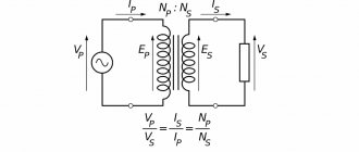
USB Type-C is a specification for a USB connector system that is gaining popularity in the field of smartphones and mobile devices. USB Type-C is capable of both delivering power and transferring data. One of the features of USB C is that, unlike its predecessors, this connector does not have a clear top or bottom, meaning it can be flipped, so you don't have to try to connect it the first time.
This article will cover some of the most important features of the USB-C standard. Before we dive into the pinouts and explain what each pin is capable of, we'll quickly cover what USB-C is and what it does best at.
What is USB-C?
USB-C is a relatively new standard that aims to provide high-speed data transfer of up to 10 Gbps, as well as power transfer capacity of up to 100 W. These features could make USB-C a truly universal connection standard for modern devices.
Some people wonder how to write it correctly: USB-C or USB Type-C? These two terms are usually used interchangeably (we'll use both in this article). Although USB-C is more commonly used, USB Type-C is the official name of the standard, as listed on USB.org.
USB-C Features
The USB-C interface has three main functions and features:
- Has a reversible connector. The interface is designed in such a way that the connector can be reversed relative to the socket.
- It supports USB 2.0, USB 3.0 and USB 3.1 Gen 2 standards. Additionally, it can support third-party protocols such as DisplayPort and HDMI in an operating mode called Alternate Mode.
- It allows devices to negotiate and select the appropriate level of power flow through the interface.
In the following sections, we will see how these features are provided by the USB Type-C standard.
USB Power Delivery Specification
| Profile | Possibility of delivery | Max power |
| 0 | Reserved | — |
| 1 | 5V and 2A | 2 W |
| 2 | 5V and 2A, 12V and 1.5A | 18 W |
| 3 | 5V and 2A, 12V and 3A | 36 W |
| 4 | 5V and 2A, 12V and 20V – 3A | 60 W |
| 5 | 5V and 2A, 12V and 20V – 5A | 100 W |
USB Type-C connector power and ground lines
The VBUS and GND pins are the power and return paths for the signals. The default VBUS voltage is 5V, but the standard allows devices to negotiate and select a VBUS voltage other than the default value. The power supply allows the VBUS to have a voltage of up to 20 V. The maximum current can also be increased to 5 A. Therefore, USB Type-C can output a maximum power of 100 W.
A high power stream can be useful when charging a large device such as a laptop. The following figure shows an example from RICHTEK where a boost converter is used to produce the appropriate voltage requested by the laptop.
Note that power delivery technology makes USB Type-C more versatile than older standards because it makes the power level adaptable to the load's needs. You can charge your smartphone and laptop with one cable.
Package.
Most cables (yes, almost all) come in a regular zip bag. Here the manufacturer got confused with such a box.
on the back side
larger
The box contains a plastic backing, the connectors are protected with shipping (and for us, operational) film. There is a certain warranty card and anyone who has already purchased products from this brand has seen the standard stickers.
RX and TX lines of USB Type-C connector
The connector has two sets of RX differential pairs and two sets of TX differential pairs. One of these two RX pairs along with the TX pair can be used for USB 3.0/USB 3.1 protocol. Since the connector is switchable, a multiplexer is required to correctly route data across the differential pairs used through the cable.
Please note that the USB Type-C port can support USB 3.0/3.1 standards, but the minimum USB Type-C feature set does not include USB 3.0/3.1. In such cases, the RX/TX pairs are not used by the USB 3.0/3.1 connection and can be used by other USB Type-C features such as Alternate Mode and the USB Power Delivery protocol. Even all available RX/TX differential pairs can use this functionality.
Prologue.
At the beginning of the review I kind of wrote it down, there’s not much to add. I am sure that many owners of all these doctors have gone through similar “Jedi paths”. It’s clear that if you just need to look at the voltage or current (without a capacitance), then the most trump cards in terms of price are the blue doctors, the downsides are that they stick out noticeably, in fact, this was the main reason for trying to replace it with something more compact.
Lines CC1 and CC2 of the USB Type-C connector
These lines are the channel configuration pins. They perform a number of functions such as cable insertion and removal detection, connector/plug orientation detection and current notifications. These pins can also be used for communications required for power supply and alternate mode.
The figure below shows how pins CC1 and CC2 determine the orientation of the connector/plug. In this figure, DFP stands for downstream output port, which is a port that acts either as a host for data transmission or as a power source. UFP stands for upstream output port, which is a device connected to a host or power sink. Flipped here means the connector is upside down, Unflipped means it's not upside down.
DFP pulls up pins CC1 and CC2 through resistors Rp, but UFP pulls them up through Rd. If the cable is not connected, the source sees a logic high on pins CC1 and CC2. Connecting a USB Type-C cable creates a current path from the 5V power supply to ground. Since there is only one CC wire in a USB-C cable, only one current path is formed. For example, in the top picture, the CC1 DFP pin is connected to the CC1 UFP pin. Therefore, the DFP CC1 pin will be below 5V, but the DFP CC2 pin will still be logic high. Therefore, by monitoring the voltage at the DFP CC1 and CC2 pins, we can determine the cable connection and its orientation in space.
In addition to cable orientation, the Rp-Rd path is used as a way to convey information about the current capabilities of the source. For this purpose, the power consumer (UFP) monitors the voltage on the CC line. When the CC line voltage is at its lowest value (about 0.41V), the source can provide the default USB power, which is 500mA and 900mA for USB 2.0 and USB 3.0 respectively. When the CC line voltage is about 0.92 V, the source can supply a current of 1.5 A. The maximum CC line voltage, which is about 1.68 V, corresponds to the source current capacity of 3 A.
Conclusions.
Minuses.
The cable is more expensive than regular cables without a screen. Shows only watts (does not show volts and amps). In 5V mode, the screen may easily not turn on (most likely it depends on the gadget and/or charger, i.e. on the presence of power along one of the lines). Pros. Actually the presence of a display meter. Manufacturing quality without any complaints. Even the box can be considered a plus, a gift made from a cable is so-so (the recipient most likely won’t even think that the cable costs $10), but you never know. There is sputtering on the contacts, the conductors have a sufficient cross-section for 6A. Thank you for reading to these words. If you have questions, write, I will try to answer. Warmth everyone!
============== until February 28th with coupon BG64a001
price is $8 for 1m cable and $9 for 2m cable. ============== As usual, I remind you that an allowance coupon of $1-2 is additionally applied (in the VIP center)
The product was provided for writing a review by the store. The review was published in accordance with clause 18 of the Site Rules.
USB Type-C connector VCONN line
As mentioned above, USB Type-C aims to provide incredibly high data transfer speeds along with high levels of power flow. These functions may require the use of special cables when using the chip internally. Additionally, some active cables use a repeat driver chip to amplify the signal and compensate for losses incurred by the cable. In these cases, we can power the circuitry inside the cable by supplying 5V, 1W power to the VCONN pin. This is shown in the following figure.
As you can see, the active cable uses resistors Ra to pull the CC2 lines to ground. The value of Ra is different from Rd, so the DFP can still determine the spatial orientation of the cable by checking the voltage at the DFP CC1 and CC2 pins. Once the cable orientation is determined, the channel configuration pin corresponding to the "active cable IC" will be connected to a 5V, 1W power supply to power the circuitry inside the cable. For example, in Figure 5, the actual path Rp-Rd corresponds to pin CC1. Therefore, the CC2 pin is connected to the power supply labeled VCONN.
USB-C power delivery
As mentioned above, devices using the USB Type-C standard can negotiate and select the appropriate level of power flow through the interface. These power negotiations are achieved using a protocol called USB Power Delivery, which is a single-wire communication over the CC line discussed above. The following figure shows an example of USB Power Delivery, where the receiver sends requests to the source and adjusts the VBUS voltage as needed. First, the 9-volt bus is requested. Once the source stabilizes the bus voltage at 9V, it sends a "ready to power" message to the sink. The receiver then requests the 5V rail and the source provides it and sends the power supply ready message again.
Importantly, these are not only negotiations related to energy delivery. In addition, other negotiations, such as those related to the alternative mode, are carried out using the Power Delivery protocol on the CC line of this standard.
Specification. TTX.
Note: the review contains black (1m) and green (2m) Baseus 66W and red (1m) Baseus 40W (1m) cables.
Stated maximum up to 66W (or 6A) for Huawei gadgets. I have only Baseus, Xiaomi and Kuula among the “load” and power supplies, so the maximum I could squeeze out was 30W. Below I will duplicate the title picture - in fact, for non-Huawei, this is what is stated.
Length: 1m, 2m Weight: 35g (1m), 79g (2m)
other cables
The tester detects the presence of an E-Marker (Power Delivery) chip.
These protocols are determined, but I think this is more relevant to my Baseus GAN 2 Pro charging
PD Listener “read” this
Measurements on 1m cable for 5V 3A, drawdown 0.17V and 0.015A.
Measurements on a 2m cable for 20V 1.5A, drawdown 0.22V and 0.07A.
Looking ahead a little, I will say that the multimeter did not encounter any resistance
I don’t see the point in posting all the “boa constrictors”, 1m is present.
More photos of the connectors, screen, braid.