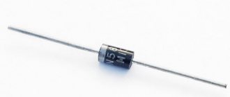
At all resistance measurement limits, the multimeter will display an infinitely low resistance or short circuit in both directions. The advantages of the latter include extremely low reverse current, which for individual Schottky diodes can amount to several picoamps, and the ability to operate components of certain brands at frequencies of up to hundreds of gigahertz and even higher. Moreover, in both cases you will not feel the smell of burning and you will not see smoke, since the housing has built-in special protection against such incidents.
The affordable cost of Schottky diodes allows you to do this almost at any time without much expense. When using a typical multimeter, the full functionality of the element can be displayed when the device is operating in the “diode” mode. Solar panels with Schottky diodes
Some time ago, I personally had a problem with the converter rectifier for a car amplifier. To make Schottky junctions, silicon is usually used as a semiconductor, and the metals and chemical compounds used are gold, platinum silicide, molybdenum, etc.
And the last diagnostic option is related to a leak: when the load on the central processor increases in multiprogram mode, the power supply turns off spontaneously. It is in such secondary power circuits that Schottky devices are most often used. Since they are placed in a single housing, their temperature conditions are the same. The product is more stable in operation than other semiconductor analogues, and the ease of manufacture and design of the Schottky diode make it a very affordable option.
The main thing is to understand the specifics of its work and use it correctly. Diode operating principle
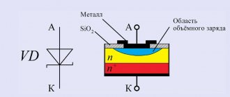
Metal and semiconductor: contact features
In the contact region of semiconductor and metal materials, the Schottky effect leads to the formation of a layer in the semiconductor that is highly depleted of electrons. It has the valve properties inherent in a semiconductor pn junction. This zone is a barrier to charge carriers, which is why these radio components are often called Schottky barrier diodes.
The elements differ from conventional semiconductor valves in the following qualities:
- reduced voltage drop at forward bias;
- insignificant own capacity;
- low reverse current;
- low permissible reverse voltage.
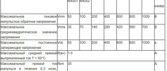
With forward bias, the potential difference across the Schottky diode does not exceed 0.5 V, while on a conventional rectifier valve the voltage drop is about 2-3 V. This is explained by the low resistance of the transition section between the semiconductor and the metal. The table below shows the characteristics of Schottky diodes.
The good frequency characteristics of Schottky diodes are due to the absence of minority charge carriers in the transition zone. Because of this, the processes of diffusion and recombination of holes and electrons that are usual for a purely semiconductor pn junction do not occur in the contact region.
Consequently, the intrinsic capacitance of this layer tends to zero. This property makes Schottky barrier diodes preferable for use in high- and ultra-high-frequency circuits, as well as equipment with pulsed operating modes - all kinds of digital devices, electronics control systems and switching power supplies.
Why is this significant?
Let's imagine a Schottky diode with excellent VF = 0.2 V, but with IR = 3 mA. In a bridge rectifier, the optimal forward voltage drop will make little difference if the rectified pulse is literally eaten up by reverse leakage currents (IR) from other diodes. Conversely, with a very small leakage current of 1 nA (as with pn junction diodes), the forward voltage drop can reach 0.8 V. Too much voltage loss in the input circuits makes it difficult to further increase it using a DC/DC converter. Therefore, it is necessary to maintain a balance between IR and VF so as to minimize power loss and bring the signal voltage as close as possible to the value at the receiving coil. ON Semiconductor has invested in R&D to optimize power loss in its new family of low power Schottky diodes using Trench technology.
The described advantages are not associated with a more complex processing process, which, in turn, can reduce the reliability of the devices. Instead, the ON Semiconductor research team focused on simplifying the manufacturing process while maintaining high quality and reliability requirements, allowing the products to be used in applications such as the automotive industry. The first series of new low power Schottky Trench diodes is now in production (NSR05T).
The next improved generation of Schottky Trench diodes is in development with extremely low power loss by optimizing VF and IR values.
Low voltage diodes
The peculiarity of Schottky diodes is that they are low voltage. If the applied potential difference exceeds a certain permissible level, then, in accordance with quantum laws, a breakdown occurs, which in a conventional semiconductor radio component can be tunneling, avalanche or thermal. After the first two, the diode is restored and continues to work properly. Thermal breakdown means fatal failure.
Schottky diode bridge
However, the sensitivity of these radio components is not always their disadvantage. For example, due to this characteristic, Schottky barrier diodes are used in particularly sensitive local oscillators, which gain the ability to process radio signals of very low power.
Main parameters:
- Maximum constant reverse voltage;
- Maximum pulse reverse voltage;
- Maximum (average) forward current;
- Maximum pulse forward current;
- Constant forward voltage across the diode at a given forward current through it;
- Diode reverse current at maximum reverse voltage;
- Maximum operating frequency of the diode;
- Reverse recovery time;
- Total diode capacity.
In diodes with a Schottky barrier, breakdown is always only thermal. This is a feature of the metal-semiconductor junction. If the reverse bias is large, the element fails and needs to be replaced. This, by the way, explains the strong sensitivity of Schottky diodes to static electricity - when installing them and servicing radio equipment with these elements, it is necessary to ground protective clothing and tools.
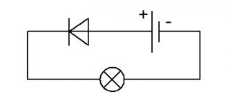
Schottky diode on an electrical circuit
Advantages and disadvantages
When working with devices that include a Schottky diode, you should consider their positive and negative aspects. If you connect it as an element of an electrical circuit, it will perfectly hold the current, preventing large losses.
In addition, the metal barrier has minimal capacity. This significantly increases the wear resistance and service life of the diode itself. The voltage drop when using it is minimal, and the action occurs very quickly - you just need to make a connection.
However, the large percentage of reverse current is an obvious disadvantage. Since many electrical appliances are highly sensitive, there are often cases when a slight excess of the indicator, just a couple of A, can damage the device for a long time. Also, if you carelessly check the semiconductor voltage, the diode itself may leak.
Expert opinion
It-Technology, Electrical power and electronics specialist
Ask questions to the “Specialist for modernization of energy generation systems”
Pros and cons The picture of the transition to an equilibrium state with the formation of a potential barrier for a p-type semiconductor and a metal is similar to the considered example with an n-type semiconductor and a metal. Ask, I'm in touch!
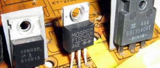
Production of Schottky diodes
Standard materials are used as semiconductor components - silicon, germanium and gallium arsenide. In the process of manufacturing radio components, metals such as gold, silver, palladium, and tungsten are sprayed onto them. It is these elements of the periodic table that provide a sufficiently high potential barrier that determines the functionality of Schottky diodes. Germanium radio components show high resistance to temperature changes, so this material is more often used than silicon and gallium arsenide in the production of diodes for high-power power supply circuits. But silicon and gallium elements demonstrate better frequency parameters.
Material on the topic: What is a condenser
Schottky diodes in power supplies
In system power supplies, Schottky diodes are used to rectify the current of the +3.3V and +5V channels, and, as is known, the output currents of these channels amount to tens of amperes, which leads to the need to take very seriously the issues of rectifier performance and reducing their energy losses. Solving these issues can significantly increase the efficiency of power supplies and increase the reliability of the power transistors in the primary part of the power supply.
It will be interesting➡ What is the Gunn effect and what do diodes have to do with it
So, to reduce dynamic switching losses and eliminate short-circuit mode during switching, in the highest current channels (+3.3V and +5V), where these losses are most significant, Schottky diodes are used as rectifier elements. The use of Schottky diodes in these channels is due to the following considerations:
- The Schottky diode is an almost inertia-free device with a very short recovery time of reverse resistance, which leads to a decrease in the reverse secondary current and to a decrease in the surge current through the collectors of the power transistors of the primary part at the moment the diode switches. This significantly reduces the load on the power transistors, and, as a result, increases the reliability of the power supply.
- The forward voltage drop across the Shockey diode is also very small, which, with a current value of 15–30 A, provides a significant gain in efficiency.
Since in modern power supplies the +12V voltage channel also becomes very powerful, the use of Schottky diodes in this channel would also give a significant energy effect, but their use in the +12V channel is impractical. This is due to the fact that when the reverse voltage exceeds 50V (and in the +12V channel the reverse voltage can reach 60V), Schottky diodes begin to switch poorly (too long and at the same time significant reverse leakage currents arise), which leads to the loss of all the advantages of their applications. Therefore, high-speed silicon pulse diodes are used in the +12V channel.
Diode devices.
Although the industry now produces Schottky diodes with high reverse voltage, their use in power supplies is considered inappropriate for various reasons, including economic ones. But there are exceptions to any rule, so in individual power supplies you can find Schottky diode assemblies in +12V channels. In modern system power supplies for computers, Schottky diodes are, as a rule, diode assemblies of two diodes (diode half-bridges), which clearly increases the manufacturability and compactness of power supplies, and also improves the cooling conditions of the diodes. The use of individual diodes rather than diode assemblies is now an indicator of a low-quality power supply.
It will be interesting➡ A few facts about the laser diode
Scope of application
The Schottky diode can be included in any battery.
It is included in the solar battery device. Solar panels, which have been successfully operating in outer space for a long time, are assembled precisely on the basis of Schottky barrier junctions. Such solar systems are installed on spacecraft (satellites and telescopes that operate in harsh conditions of airless space).
The device is indispensable when operating computers, household appliances, radios, and power supplies. When used correctly, a Schottky diode increases the performance of any device and prevents current loss. It is capable of receiving alpha, beta and gamma radiation. That is why it is indispensable in space conditions.
The Schottky diode is an indispensable element in many electronic devices. The main thing is to understand the specifics of its work and use it correctly.
Useful tips Connection diagrams Principles of operation of devices Main concepts Meters from Energomer Precautions Incandescent lamps Video instructions for the master Testing with a multimeter
0 LED markings pros and cons application in electronics scope of application
Did you like the article? Share with friends:
You may also be interested
Electrical equipment 0
What does Voltage Loss in Wires Depend on? How to Reduce Losses
Voltage loss in power line wires Voltage difference at the beginning and end of the line U1-U2,
Electrical equipment 0
How to Choose LED Ceiling Light for Home Choices for Ceiling
How to choose ceiling lamps - useful tips on how much and where to install, how they differ and
Electrical equipment 0
LED Ceiling Panels 300x300 Led Ultrathin Price Various in shape
LED panels in Leroy Merlin Manufacturer's warranty (years) 1 Installation type Recessed Diameter
Electrical equipment 0
Current Transformer Transformation Ratio t 0 66 Current Transformer
Methodology for testing current transformers Terminals of secondary windings (two or more) and current transformer housing
Electrical equipment 0
Lamp Low and High Beam h4 Pinout Types of lamps h4
The best H4 lamps with increased luminous efficiency Advantages the highest luminous output value available; clear
Electrical equipment 0
Osram Night Breaker Laser H11 Reviews Other questions
Guarantees and returns Guarantees We work under an offer agreement, which is a legal guarantee that
Add a comment Cancel reply
Manifestation of faults in Schottky diodes
As already noted, the failure of Schottky diodes is one of the main problems of modern power supplies. So what preliminary signs can be used to presumably determine their malfunction? There are several such signs. Firstly, in the event of breakdowns and leaks of the secondary rectifier diodes, as a rule, the protection is triggered and the power supply does not start. This can manifest itself in different ways:
- When the power supply is turned on, the fan “twitches,” that is, it makes several revolutions and stops; After this, the output voltages are completely absent, i.e. the power supply is blocked.
- After turning on the power supply, the fan “twitches” constantly, voltage ripples can be observed at the outputs of the power supply, i.e. the protection is triggered periodically, but the power supply is not completely blocked.
- A sign of a malfunction of Schottky diodes is extremely strong heating of the secondary radiator on which they are installed.
- A sign of Schottky diode leakage may be spontaneous shutdown of the power supply, and therefore the computer, when the load increases (for example, when running programs that ensure 100% processor load), as well as the inability to start the computer after an “upgrade”, although the power supply is sufficient.
In addition, it is necessary to realize that in power supplies with poor and ill-conceived circuit design, leakage of rectifier diodes leads to overloads of the primary circuit and to current surges through the power transistors, which can cause their failure. Thus, a professional approach to repairing power supplies dictates a mandatory check of the secondary rectifier diodes each time the power transistors-switches of the primary part of the power supply are replaced.
Material on the topic: What is a time relay
Diagnostics of Schottky diodes
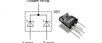
Testing and accurate diagnostics of Schottky diodes, in practice, is quite a difficult task, since much here is determined by the type of measuring instrument used and the experience of such measurements, although determining the usual breakdown of one or two diodes of a Schottky diode assembly is not particularly difficult. To do this, you need to unsolder the diode assembly and check both diodes with a tester according to the diagram in Fig. 5. For such diagnostics, the tester must be set to diode testing mode. A faulty diode will show the same resistance in both directions (usually very small, i.e. it will show a short circuit), which indicates its unsuitability for further use. However, obvious breakdowns of diode assemblies are very, very rare in practice.
Basically, you have to deal with leaks (and often thermal leaks) of Schottky diodes. But leaks cannot be detected this way. When tested with a tester in the “diode” mode, a “leaking” diode is in the vast majority of cases fully operational. Guaranteed diagnostic accuracy, in our opinion, can only be achieved by replacing the diode with a known-good similar device.
But still, you can try to identify a “suspicious” diode using a technique that involves measuring the resistance of its reverse junction. To do this, we will not use the diode testing mode, but a regular ohmmeter.
Attention! When using this technique, it should be remembered that different testers may give different readings, which is explained by differences in the testers themselves.
So, we set the measurement limit to the value [20K] and measure the reverse resistance of the diode (Fig. 6). As practice shows, serviceable diodes at this measurement limit should show infinitely high resistance.
The operating principle of a Schottky diode.
If the measurement reveals some, usually small, resistance (2–10 kOhm), then such a diode can be considered “very suspicious” and it is better to replace it, or at least check it using the replacement method. If you check at the measurement limit [200K], then even serviceable diodes can show very little resistance in the opposite direction (units and tens of kOhms), therefore it is recommended to use the limit [20K]. Naturally, at large measurement ranges (2 MΩ, 20 MΩ, etc.), even an absolutely serviceable diode turns out to be completely open, since its pn junction is applied too high (for Schottky diodes) reverse voltage. At the [200K] limit, you can check using the comparative method, i.e., take a guaranteed-functional diode, measure its reverse resistance and compare it with the resistance of the diode being tested. Significant differences in these measurements will indicate the need to replace the diode assembly.
It will be interesting➡ What are field-effect transistors?
Sometimes there are situations when only one of the diodes in the assembly fails. In this case, the fault is also easily identified by comparing the reverse resistance of two diodes of the same assembly. Diodes of the same assembly must have the same resistance. The proposed method can also be supplemented by testing for thermal stability. The essence of this check is as follows. At the moment in time when the resistance of the reverse junction is checked at the measurement limit [20K] (see the previous paragraph), it is necessary to touch the contacts of the diode assembly with a heated soldering iron, thereby heating its crystal.
A faulty diode assembly almost instantly begins to “float”, i.e. its reverse resistance begins to decrease very quickly, while a serviceable diode assembly maintains the reverse resistance at an infinitely large value for a long time. This check is very important, because during operation the diode assembly gets very hot (it’s not for nothing that it is placed on a radiator) and, due to heating, changes its characteristics. The considered technique provides a test of the stability of the characteristics of Schottky diodes to temperature fluctuations, because increasing the housing temperature to 100 or 125°C increases the value of the reverse leakage current by a hundred times (see data in Table 1).
This is how you can try to check a Schottky diode, but the proposed methods should not be abused, i.e. you should not carry out tests at too high a resistance measurement limit and heat the diode too much, because theoretically, all this can lead to damage to the diode.
In addition, due to the possibility of failure of Schottky diodes under the influence of temperature, it is necessary to strictly adhere to all recommended soldering conditions (temperature conditions and soldering time). Although we must pay tribute to diode manufacturers, since many of them have achieved that the installation of assemblies can be carried out at a high temperature of 250 ° C for 10 seconds.
Testing and interchangeability
Schottky rectifiers can be tested in the same way as conventional semiconductors, since they have similar characteristics. You need to ring it in both directions with a multimeter - it should show itself in the same way as a regular diode: anode-cathode, and there should be no leaks. If it shows even a slight resistance - 2-10 kilo-ohms, this is already a reason for suspicion.
Checking a Schottky diode with a multimeter
A diode with a common anode or cathode can be tested like two ordinary semiconductors connected together. For example, if the anode is common, then it will be one leg out of three. We place one tester probe on the anode, the other legs are different diodes, and another probe is placed on them.
Can it be replaced with another type? In some cases, Schottky diodes are replaced with ordinary germanium diodes. For example, D305 at a current of 10 amperes gave a drop of only 0.3 volts, and at currents of 2–3 amperes they can generally be installed without radiators. But the main purpose of the Schottky installation is not a small drop, but a low capacity, so replacement will not always be possible.
As we see, electronics does not stand still, and further applications of high-speed devices will only increase, making it possible to develop new, more complex systems.
Source