USB cable pinout refers to the description of the internals of the Universal Serial Bus. This device is used to transfer data and charge batteries of any electronic devices: mobile phones, players, laptops, tablet computers, tape recorders and other gadgets.
Carrying out high-quality pinouts requires knowledge and ability to read diagrams, orientation in the types and types of connections, you need to know the classification of wires, their colors and purpose. Long-term and uninterrupted operation of the cable is ensured by the correct wire connection of the 2 USB and mini-USB .
Types of USB connectors, main differences and features
The Universal Serial Bus comes in 3 versions - USB 1.1, USB 2.0 and USB 3.0. The first two specifications are completely compatible with each other; bus 3.0 is partially compatible.
USB 1.1 is the first version of the device used for data transfer. The specification is used only for compatibility, since 2 operating modes for data transfer (Low-speed and Full-speed) have a low speed of information exchange. Low-speed mode with a data transfer rate of 10-1500 Kbps is used for joysticks, mice, and keyboards. Full-speed is used in audio and video devices.
A third operating mode has been added to USB 2.0 - High-speed for connecting information storage devices and video devices of a higher organization. The connector is marked with HI-SPEED on the logo. The information exchange speed in this mode is 480 Mbit/s, which is equal to the copy speed of 48 MB/s.
In practice, due to the design and implementation features of the protocol, the throughput of the second version turned out to be less than declared and amounts to 30-35 MB/s. The 1.1 and 2nd generation Universal Bus specification cables and connectors are identical in configuration.
The third generation universal bus supports a speed of 5 Gbps, equal to a copy speed of 500 MB/s. It is available in blue, which makes it easier to determine whether the plugs and sockets belong to the advanced model. Bus 3.0 current increased from 500 mA to 900 mA. This feature allows you not to use separate power supplies for peripheral devices, but to use the 3.0 bus to power them.
Types of existing USB connectors
Next, we are going to describe the differences between the different types of USB connectors that can be found in various devices available in the market as well as PC motherboards.
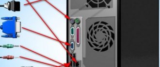
USB Type A and Type B
The first type of USB port to hit the market, and therefore the oldest, had a blank line for versions 1.0 and 2.9, but as of version 3.0 a blue color was adopted to distinguish them from previous generations. If you look at the images above these lines, you will see that the port has 4 lines, one of them is its power supply, then we have another one for ground and two data ports.
Considering that USB is a serial port and not parallel, this means that it transmits 1 bit for each clock signal, so since there are two communication channels, we can easily conclude that the pin transmits data in one direction and in others are the opposite. So you can send and receive data simultaneously with the device. USB Type B, on the other hand, is square in shape and is used for devices such as printers and scanners. Except for its different shape, the characteristics are the same as Type A, so it also uses a 4-pin connector with exactly the same configuration.
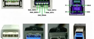
Beginning with version 3.0 of the standard, these two types of USB ports changed configuration by adding additional pins on the back of the port. Adding two of them to transmit data, SSTX- and SSTX+, and two more to receive data, SSRX- and SSRX+, thereby increasing the amount of data transferred per clock cycle. These additional ports allow for up to ten times more throughput compared to the second generation standard.
Mini-USB and Micro-USB, types for small devices
The boom in cell phones, personal digital assistants, MP3 players, and early digital cameras that began in the late 1990s and early 2000s created a clear need. A smaller USB connector was required than those previously used.
The first of these connectors was Mini-USB, which adds an additional pin to the four already used in the other types. The new pin has to do with OTG or On the Go mode, which serves to indicate that the device is slave to another in terms of power supply.
Over the years, due to the need to have a power and data port for smartphones, each time smaller and thinner, another type of USB connector was created, which we know as Micro-USB. This is nothing more than an even smaller version of the USB port that is used in a lot of phones and tablets, but due to its inability to provide fast enough charging, it is gradually being replaced.
There is a third type of Micro-USB cable called Type B, which, as indicated by its blue color, is used for devices with data rates of USB 3.0 and higher, although due to its different shape it is not backwards compatible with connectors. Previously Micro-USB. As you might have guessed, it adds additional pins that were also added to the Type A and Type B connectors, but in the end, this type of USB port is completely obsolete.
USB-C, the one that will replace other types
We come across the most advanced of all, and the one that will eventually replace the other types without delving into the USB 4.0 standard is the standard connector, and due to its size and shape, it will eventually replace the other types. ports over time. This is because there are provisions for it and because it solves the problem of fast charging in the case of Micro-USB. USB Type C first appeared with the third generation of the standard and therefore does not have versions 2.0 and earlier.
If we look at the USB Type C pin distribution, we can see that it is really two USB Type A connectors in one. We have to run the data pins TX1-, TX1+, TX2+ and TX2-, which obviously transmit data in one direction, and their counterparts RX1-, RX1+, RX2+ and RX2-, which will serve to receive data. So it really works as if it were 4 USB ports in one device, with proper ground and power pins. These aren't the only data pins though, as we have D- and D+ pins which transfer at the same speed as the USB 2.0 standard and are used when the other communication pins are available.
The reason for this is that USB Type-C can also be used to transfer video in DisplayPort Alternate or Alt DP mode. In which the TX and RX lines of the cable are used for video output, leaving only the D and D+ pins for data transfer in the specified transmission mode. Which makes it an ideal connector for connecting a virtual reality headset.
The Future of USB Connector Types
Although the most important novelty is the ability to power peripheral devices that require high power. While a USB 3.2 Type A port can output 15W, its Type C counterpart can output up to 100W, and with the fourth generation of the standard we are expected to reach 240W. This is more than enough to replace computer power ports. laptops and a large number of devices that we use at home, such as the TV in the living room.
It is more than possible that in the future we will not see monitors directly connected to the current one, but that they will be powered by the same USB Type C port from which they receive data. The opposite could also happen, and we'd end up with game consoles without a built-in power supply that send a video signal at the same time as the TV that feeds them.
Classification and pinout
When describing and designating tables of USB connectors, it is accepted by default that the view is shown from the outside, working side. If the view is from the installation side, this is specified in the description. In the diagram, the insulating elements of the connector are marked in light gray, the metal parts are marked in dark gray, and the cavities are marked in white.
Despite the fact that the serial bus is called universal, it is represented by 2 types. They perform different functions and provide compatibility with devices with improved characteristics.
Type A includes active, power supply devices (computer, host), type B includes passive, connected equipment (printer, scanner). All sockets and plugs of the second generation and version 3.0 type A buses are designed to work together. The Gen3 Type B jack connector is larger than what is needed for the 2.0 Type B plug, so a device with a Gen 2.0 Type B connector is connected using only a USB 2.0 cable. Connection of external equipment with modification 3.0 type B connectors is carried out using cables of both types.
Classic Type B connectors are not suitable for connecting small electronic equipment. Connecting tablets, digital equipment, and mobile phones is done using miniature Mini-USB connectors and their improved Micro-USB modification. These connectors have reduced plug and socket sizes.
The latest modification of USB connectors is type C. This design has identical connectors at both ends of the cable and is characterized by faster data transfer and greater power.
What is pinout
The pinout of a USB connector is the order in which the necessary elements are placed in the plug using a special serial bus in its various variants.
These days, USB is the most famous interface, which was created in 1996. This model was created with the aim of connecting various devices to a computer and so that it could replace outdated models.
Every year, information about the creation of such a wire spread around the world more and more. Now it’s difficult for us to imagine any other version of the charger.
Of course, some companies still do not use the USB circuit for their models, but most companies still prefer this option.
Nowadays everyone uses USB to transfer data from electronic media and as a charger. To carry out high-quality pinouts, you will need a lot of knowledge, which consists of understanding various types of circuits, orientation in connections, knowledge of wire typology, etc.
USB 3.0 pinout types A and B
Bus version 3.0 has a 10 or 9 wire connection. 9 pins are used if Shield wire is missing. The contacts are arranged in such a way that devices of earlier modifications can be connected.
USB 3.0 wiring:
- A - plug;
- B - socket;
- 1, 2, 3, 4 - contacts that match the pinout of the contacts in specification 2.0, have the same color scheme;
- 5, 6 contacts for data transmission via the SUPER_SPEED protocol are designated SS_TX- and SS_TX+, respectively;
- 7 - grounding GND;
- 8, 9 — contact pads of wires for receiving data via the SUPER_SPEED protocol, contact designation: SS_RX- and SS_RX+.
USB connector compatibility
If we talk about the compatibility of USB connectors with each other, then the first and second types of USB connectors are compatible with each other. If you connect a device designed to work with USB 2.0 into connector 1.1, the user will receive a system message stating that this device can work faster (it will work, although not as fast as it would with 2.0).
USB 2.0 and 3.0 connectors are also partially compatible; you can easily plug a device designed for a 2.0 connector into a 3.0 connector, and it will work. However, you cannot plug a device designed for a 3.0 type connector into a 2.0 connector.
Micro-USB connector pinout
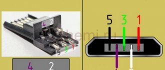
The Micro-USB cable has 5-pin connectors. A separate mounting wire in insulation of the desired color is supplied to them. To ensure that the plug fits accurately and tightly into the socket, the upper shielding part has a special chamfer. The micro USB pins are numbered 1 to 5 and read from right to left.
The pinouts of micro- and mini-USB connectors are identical; they are presented in the table:
| Wire number | Purpose | Color |
| 1 | VCC power supply 5V | red |
| 2 | data | white |
| 3 | data | green |
| 4 | ID function, for type A shorted to ground | |
| 5 | grounding | black |
What other options are there?
So, we list all the options with which you can solve the problem of not having the necessary cable:
- Buy the required cable at .
- The barbaric method is above.
- Soldering iron and pinout (and donor wires or plugs for our Frankenstein).
The last option has a right to life. If the required cable is not on sale, it is often easier to buy a plug instead of a whole donor cable. You can always find the necessary pinout on the Internet. In order to restore or charge with a suitable connector, you will have to solder only two wires (red - plus and black - minus).
I would personally advise: if you are not a professional, do not try to re-solder USB with HDMI, eSATA, 30pin, Lightning and others connectors, because there is a high chance of simply ruining the wires. In this case, it is better to throw off the toad that is strangling you and fork out for a normal wire than to overpay twice.