The need to determine phase, zero and grounding arises when installing sockets to which unmarked conductors are suitable. Therefore, before installing an outlet, it is worth finding out what each specific wire is responsible for.
After reading this article, you can learn how to determine zero, phase and ground in a network using a screwdriver, multimeter or improvised means.
Using an indicator screwdriver
Two-wire network
Residents of old houses will have to deal with such wiring. This option is designated as TN-C and its essence is that the neutral wire, which is grounded at the substation, is also grounding. That is, in a two-wire network you simply will not find a grounding conductor, since its functions are performed by zero. The phase with zero is determined simply: attach the indicator to each of the wires, if there is contact with the phase, the indicator lamp will light up.
It is worth noting that this wiring option is outdated, since all plugs of new electrical appliances have three terminals.
Methods for determining zero, phase and grounding may differ depending on the system of conductors that run in the room.
Three-wire network
This type of network involves introducing three conductors into an apartment or house. The three-wire network is divided into several types. If you disassemble the TN-S system, then the protective grounding and zero are removed from the supply substation separately.
The purpose of the wires in this type of electrical network can be found out in this way:
- determine the phase in the distribution box or panel using an indicator;
- the remaining ones are zero and protective ground. It is worth disconnecting one of the wires from the shield;
- If you turn off the working zero, then all electrical appliances in the room will turn off. Using the method of exclusion, we obtain the definition of the third conductor, which performs the functions of protective grounding.
Now it’s worth finding out the phase, neutral and ground in the socket (if they are not indicated by different colors of the winding). Take the socket into which the lamp is screwed in and the wires are brought out, and touch one of them to the phase that you have already found with the indicator. With the second wire coming out of the cartridge, touch the two remaining wires in turn. If the zero on the panel is not turned on, the lamp will light up only when it touches the ground.
When handling TN-CS type wiring, protective grounding and zero diverge not from the substation, but when the conductors are introduced into the room. In this case, you should be guided by the plan that was described to determine the purpose of the TN-S system wires. Also, by examining the place where the PEN is separated, you can distinguish the working zero from the ground by the cross-section of the core.
When grounding is carried out by the TT system, the house is equipped with its own grounding device, from which protection is wired. In this case, zero, phase and ground are determined by finding the ground wire along the laying route.
Concepts of zero and phase
Electrical energy in a residential building comes from a transformer substation, the main purpose of which is to convert high voltage, most often to 380 V. Electricity is supplied to houses underground or overhead to the input distribution board. Then the voltage is supplied to the panels of each entrance. Only one phase with zero enters the apartment from it, i.e. 220 V and protective conductor (depending on the design of the electrical wiring).
Thus, the conductor that supplies current to the consumer is called phase. Inside the transformer, the windings are connected in a star with a common point (neutral) grounded at the substation. It is connected to the load with a separate wire. The neutral, which is a common conductor, is designed to allow current to flow back to the source of electricity. In addition, the neutral wire equalizes the phase voltage, i.e. value between zero and phase.
Ground, often referred to simply as ground, is not connected to voltage. Its purpose is to protect a person from the effects of electric current at the moment of problems with the consumer, i.e. in case of breakdown on the body. This can occur when the insulation of the conductors is damaged and the damaged area of the device body touches. But since consumers are grounded, when dangerous voltage occurs on the frame, grounding attracts the dangerous potential to the safe ground potential.
Using a tester or multimeter
Using a multimeter, you can try to determine the voltage passing between the conductor and the water supply or heating pipes. However, there will not be a 100% correct result. Often, the voltage between the phase and the water supply or heating system is equal to 220 V (in any case, the voltage should be higher than its value between the heating pipe and zero). But your measurements can be disrupted, for example, by a neighbor who “rewinds” electricity by choosing a heating pipe as grounding.
Of course, the best device for determining the phase is a screwdriver, which is combined with an indicator. I would like to believe that any owner who has a multimeter probably also has an indicator.
If you use a multimeter to determine the assignment of the conductors in a three-wire phase, it can show the voltage between the phase and one of the two remaining wires. Having thus learned the phase, you can use the above method and determine the protective zero and the working zero. We are talking about disconnecting one of the zeros and determining their purpose using a lamp in the socket.
Using a homemade “control”
There are times when it is urgent to connect an electrical device, but the household does not have the necessary instruments to determine phase and zero. Often this happens in a country house far from the benefits of civilization. However, finding an electric light bulb, its socket and a piece of electrical wire there is not a big problem.
Making your own control light is not difficult. It is enough to connect two wires to the socket and screw a light bulb into it. For ease of operation, equip the ends of the wires with probes (if you can find them).
The principle of identifying wires with a “control” is no different from how to determine phase and zero with an indicator screwdriver. To determine the phase, one of the “control” contacts should be connected to any of the wires being tested, and the second contact should be connected to ground. If the lamp glows, you will know that it belongs to a phase.
The main disadvantage of using homemade “control” is the lack of safety during the work. There is a real possibility of receiving an electric shock.
Other things to consider
By studying the markings of current-carrying conductors, you can make it easier for yourself to find out their purpose:
- The land is marked with the Latin letters PE. When combining the functions of the working and protective zero, the PEN marking follows. Yellow insulation is used, with one or two green stripes;
- zero is designated as N, its insulation is made in blue or light blue. Also sometimes found with a white stripe on a blue background;
- The phase marking is the Latin letter L. In the case of a three-phase network, the designation will be the letters A, B or C. The insulation is made in any color except those listed above. In practice, in all cases, the color is black, red or brown.
Often, determining phase, neutral and ground using a screwdriver or tester is a last resort, since most wires are marked with different colors or letters.
If you are familiar with the rules for installing electrical wiring, then determining phase, zero and ground will not be a problem for you. The phase comes into the fuse panel or electrical switch. The zero is mounted on a bus, which is equipped with several terminals. Also, in old shields and terminal boxes, ground and neutral were mounted with a bolt under a nut, which was welded to the box body.
How to determine phase and zero with a multimeter
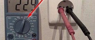
A device that measures voltage, current and resistance is called a multimeter. To identify the phase and neutral wires with its help, you first need to configure the device, for which you select the required measurement limit. In the case of digital instruments, set 600, 750 or 1000 “ ~V ” or “ ACV ”.
The phase is determined as follows: one of the probes of the device is connected to the contact of a socket or cable, and the second probe is touched by hand. If the display shows a value of about 200 V, this will indicate the presence of a phase. Indications may vary depending on floor finish, shoes, etc. If the device displays zeros or a voltage within 5-20 V, then the contact corresponds to zero.
What to do if the house does not have grounding
Lack of grounding can lead to negative consequences in the form of electric shock or breakdown of electrical appliances.
There are 2 options to solve the problem:
- Arrangement of a protective circuit near the entrance to the entrance (if the residents of the house agree among themselves and hire electricians).
- Installation of a residual current device on load lines.
When choosing the first method, a copper core with a cross-section of more than 4 square meters is laid from the common panel to the basement along the installation riser. mm. A hole is dug next to the entrance and a structure of three metal corners connected to each other by welding with wide iron strips is installed in it. A lowered copper ground wire is attached to one of the corners.
In apartments, the wiring should be updated by laying a three-core cable. Then connect it to the shield and grounding plate.
The second method involves installing residual current devices in the apartment. These devices respond to current leaks from the housings of equipment and household appliances and quickly disconnect the damaged line from the general electrical network.
In some cases, residents connect the protective wire to the central heating battery to arrange grounding, assuming that the heating riser will serve as a natural grounding conductor. This method is very dangerous.
The heating pipe does not guarantee a reliable connection to the ground within normal limits (no more than 30 ohms). Over time, the joints and connections become covered with rust and conduct current poorly, and the unhindered flow of electricity into the ground in the event of an accident is not ensured.
Dangerous voltage from electrical appliances with a damaged wire flows through the grounding conductor to the battery. If you touch it, you can get an electric shock.
Useful tips and general recommendations
Working with electrical wiring requires care and caution.
Electricians advise:
- Do not rely entirely on the color differentiation of wires or their markings; check the contacts with testers again. Cases of violation of electrical installation standards are not uncommon.
- If possible, avoid determining the voltage in conductors using a “tester” or a potato. Such methods are considered extreme, and it is better not to abuse them without experience.
- When using a multimeter, read the instructions in detail before use. Pay attention to the device settings.
Installing wiring according to standards will facilitate further connection of receivers and extend the service life of the entire electrical network. In addition, compliance with the necessary installation standards will make electricity consumption comfortable and safe.
Source
Determining the phase position by the color of the wire insulation
The neutral working wire is equipped with blue insulation, the ground is yellow-green. Accordingly, the phase has a red (brown) color. The rule can be grossly violated. Older houses were often equipped with two-core wires. The insulation color in each case is white. Some devices, such as light or motion sensors, have a different layout. For example, the neutral wire is black. Here, get ready to look at the instruction manual, there are countless layout options.
Find the neutral wire in the apartment
According to the rules, the housing of the access panel is grounded. It is carried out using a solid-sized terminal, tightened with a powerful bolt in houses of old construction; it is easier for residents of modern buildings to navigate by the number of cores. The zero bus has the largest number of connections, the phases are separated into apartments (good electricians hang up stickers A, B, C; evil ones don’t). We can easily follow the layout of circuit breakers and meters.
230 volt UK plug
In each case, the common wire will be zero. Color does not play a decisive role. Although according to standards, modern cables are equipped with colored insulation. Please note - if the house is equipped with grounding, there are at least 5 cores at the input. The panel body is mounted on a yellow-green one. The neutral wire will serve to drain the operating current from the devices (closes the circuit). Merging branches on the consumer side is prohibited. Here are three rules to help you understand the entrance panel (please note, according to the rules, the tenant should not show his nose there at all - we have warned):
- The circuit breaker breaks the phase. There are two-pole models; they are used relatively rarely for rooms with particular danger (bathroom). Therefore, by the position of the wire you can tell: this is a phase. Then it’s worth turning off the machine and ringing the wire on the side of the apartment. It will definitely give the phase position.
- The voltage between the neutral wire and any phase is 230 volts. Based on the key characteristic, we will select a vein that gives the specified difference to another. The spread between phases is 400 volts. The percentage values are 10 percent higher; Russian networks are trying to meet European standards.
- We use current clamps to measure the values on the conductors. A value will appear for each phase, the sum of which (in three) should flow back into the network via zero (or a suitable phase). Grounding is rarely used; the current here is close to zero when the branches are evenly loaded. The place where the value is greatest is traditionally the neutral conductor.
- The grounding terminal of the distribution board is visible. The sign will help you find the neutral wire in houses with NT-CS. In other cases, grounding is supplied here.
Checking the indicator light
It’s worth mentioning right away that this method of verification is very dangerous. It is recommended to carry out all manipulations taking into account safety rules and only wearing rubber gloves.
Make your own control light. For this you need the following materials:
- an ordinary incandescent lamp with a socket in working condition;
- 2 multi-core wires, about half a meter long.
The cores are attached to different sockets of the cartridge. One wire is connected to the metal object, and the other to the core that needs to be identified.
Determining the result of such a check is very simple.
If the light bulb lights up, it means there is a phase conductor; if no reaction occurs, then it is zero.
By the way, if you don’t have a regular light bulb at hand, you can just as easily check it using a neon lamp.
Why do you need to know where the phase is?
Determining the phase conductor is necessary in the following cases:
- Installation of switches
. Light switches only open the phase. If you mix it up and put a zero on the switch, then the socket will always be energized and replacing light bulbs or repairing the socket can be dangerous to human life. - Installation of automatic machines
. Typically, single-contact circuit breakers are used, and only the phase enters them. Zero remains unconnected. Therefore, in order not to confuse and set a zero on the machine, it is necessary to clearly identify the phase wire.