In any electrical network, voltage loss occurs under the influence of various factors. These are mainly parameters such as conductivity and resistance that should be taken into account when performing calculations. For DC circuits, you can get by with the usual characteristics. However, when using alternating current, you will need to calculate the active and inductive reactance of the cables. In order to correctly navigate these parameters, you need to have a good understanding of the features of each of them.
What is resistance, its nature
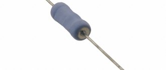
Resistance (denoted by the Latin letter R) is one of the main characteristics of conductors. Depending on the application, this property can play both a positive and negative role when using a conductor.
First of all, metals and metal alloys can be conductors. Atoms in a metal have free electrons, which are charge carriers. Electrons in a metal are constantly moving randomly from atom to atom. If an electric current is connected to them, their movement becomes orderly. When an electron collides with an atomic structure, the electron transfers its energy to the metal, thereby heating it. The more structural obstacles in the path of the electron, the greater the R of the metal.
Features of active resistance
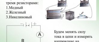
Active resistance is a unit that shows R at the section in an electrical circuit at which electrical energy is converted into thermal, mechanical or any other energy. Due to the fact that alternating current flows unevenly, R of alternating and direct current will differ when their parameters are equal. This rule applies to electrical cables and power lines. But for electrical cables made of non-ferrous metals with an alternating voltage frequency of 50 Hertz, this rule is practically inapplicable, since in this case the active R is always the same at any current.
Steel electrical wires have better active R compared to non-ferrous metals.
ACTIVITY
- Video surveillance
Order an estimate - Security alarm
Order a quote - Access control
Order a quote - Fire alarm
Order a quote - Fire extinguishing
Order an estimate - Fireproof barriers
Order a quote - Fire retardant treatment
Request a quote - Category calculation
Order calculation - Automation
Order calculation - Frequency drive
Order calculation - Energy metering
Order a calculation - Lightning protection, Grounding
Order calculation - Electrical installation
Order an estimate - Local networks and SCS
Order a calculation - Satellite communications
Order a quote - Audio and video systems
Order a quote
Calculation of inductive and capacitive reactance is carried out using the formulas:
XC=1/(2π×F×C); XL=2π×F×L
X L - Inductive reactance, (Ohm)
X C - Capacitance, (Ohm)
F — Signal frequency, (Hz)
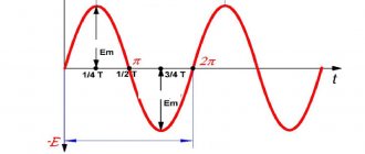
The calculation will be valid only for a sinusoidal current.
To calculate any parameter, you must enter two other values.
| Calculation of inductive and capacitive reactance | |
| Units of measurement when calculating capacity: | kHz, nF, Ohm MHz, pF, Ohm |
| Units of measurement when calculating inductance: | kHz, mH, Ohm MHz, μH, Ohm |
| Signal frequency: | |
| Value (capacitance or inductance): | |
| Reactance: | |
| *Input format – x.xx (delimiter – dot) |
| Please send your wishes, comments, recommendations for improving the calculations section on our website by email [email protected] Copying java scripts is permitted provided a link to the source is provided. |
ALL CALCULATIONS
Resistivity
Resistivity (ρ) is a unit that shows the ability of a conductor to impede the passage of electric current.
It can be used to evaluate the parameters of electrical conductors made of different materials. ρ of the conductor always increases with increasing length and decreasing cross-section; in the international system, the length of the conductor is 1 meter and the cross-section is -1 mm2.
Similar: Which cable to use for wiring in an apartment
Active resistance of wires, cables and lines
Due to the fact that alternating current flows unevenly, under the same conditions, alternating and direct current R will be different. As already mentioned, steel electrical wires have a better active R compared to conductors made of non-ferrous metals, which have the same R at any current strength.
On the contrary, the active R of steel electrical cables always depends on the electric current, so DC conductivity is never used in this case. The active R of an electrical cable is determined using the formula: R=l/y*s.
Content
- 1 Differential equations of a long line 1.1 Linear parameters 1.2 Equivalent diagram of a section of a long line 1.3 Telegraph equations 1.4 Line regularity condition 1.5 Homogeneous wave equations of a long line 1.6 Field distribution of the incident wave
2 Complex voltage reflection coefficient 3 Traveling and standing wave coefficients 4 Input impedance of a long line 5 Operating modes of a long line
- 5.1 Traveling wave mode 5.2 Standing wave mode 5.3 Mixed wave mode
6 Lossless line
- 6.1 Open line 6.2 Closed line 6.3 Capacitive load 6.4 Inductive load 6.5 Resistive load 6.6 Complex load
7 Efficiency of a line with losses 8 Limits of applicability of the long line theory 9 See also 10 Notes
//
[/td]
Long line
- a regular transmission line[1], the length of which exceeds the wavelength (
λ
) of oscillations propagating in the line.
A characteristic feature of long lines is the manifestation of interference between two waves propagating towards each other. One of these waves is created by an electromagnetic oscillation generator connected to the line and is called incident.
.
Another wave may arise due to the reflection of the incident wave from the load connected to the opposite end of the line and is called reflected
. The reflected wave propagates in the direction opposite to the incident wave. The entire variety of processes occurring in a long line is determined by the amplitude-phase relationships between the incident and reflected waves.
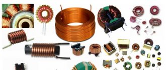
Inductive reactance of wires, cables and lines
Inductive R for one km with fifty hertz is determined using a special formula:
- x=0.144*lg(2*a(cp))/d+0.016*μ=x0'+x»0,
- a(cf) – cf. length between the axis of several wires, in more detail
- a(cp)=3 root(a1*a2*a3),
- a1, a2 and a3 are the length between the axis in different phases. d is the outer diameter. μ—relative magnetic permeability. x'0 is external outside the line. x»0 - internal inside the line.
Cable insulation resistance
To find R cable insulation, you need to proceed from its type. There are the following varieties:
- 1000 V and more - high voltage.
- Below 1000 V - low voltage.
- Control electrical cables - protective circuits, secondary circuits of switchgear (indicative relays), power circuits of electric drives, and so on.
To measure R insulation, a specialized device is required. High-voltage and low-voltage are determined at a voltage of 2500 V, when control ones are from 500 to 2500 V. If a high-voltage one with a value greater than 1000 V is used, then its insulation R must be at least 10 MOhm. If a low-voltage one with a value of less than 1000 V is used, then its insulation R must be at least 0.5 Mohm. Control cables must have insulation R of at least 1 MOhm.
High voltage wires with zero resistance
High-voltage wires with zero R are better and more reliable than conventional ones; due to the use of silicone in them, they do not become hard in the cold, and do not become dry over time and temperature.
“Zero” high-voltage wires have a difference compared to conventional high-voltage wires with polymer cores: R in them is measured in Ohms and tenths of Ohms, while in ordinary ones it is measured in thousands.
In addition, it has other advantages, primarily a longer service life.
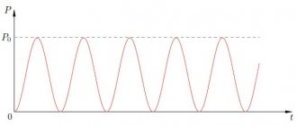
Traveling and standing wave coefficients
The voltage diagram is used to judge the degree of coordination of the line with the load. For this purpose, the concepts of the traveling wave coefficient
—
k
BW and
standing wave coefficient k
SV:
| (17) |
| (18) |
These coefficients, judging by the definition, vary within the limits:
| , | . |
In practice, the concept of standing wave ratio is most often used, since modern measuring instruments (panoramic k
SV) on indicator devices display the change in this particular value in a certain frequency band.
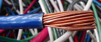
Bimetallic cable
Bimetallic cables consist of ordinary steel wire coated with copper and have a low specific R. Bimetallic electrical cables are made from a small amount of copper, which significantly reduces their cost. At the same time, they are able to withstand 5 times more load than pure steel, and 6 times more than copper. In this regard, they are actively used in power lines, as well as buses of distribution devices and various parts of electrical appliances.
When choosing conductors, it is necessary to take into account the conditions of their operation and, in accordance with them, select a cable with suitable properties, primarily resistance.
Calculation of basic parameters
Link options
Power lines, transformers and switches can act as connections, that is, circuit elements that connect two circuit nodes. Let's consider how their parameters are determined.
Power lines
As a rule, when calculating steady-state conditions on a PC, the power transmission line is represented by a U-shaped equivalent circuit (Figure 1).
A power line is characterized by longitudinal resistance and transverse conductivity
Conductance
The active conductivity of overhead lines is almost entirely determined by corona losses, and therefore it strongly depends not only on the design of the line, but also on the operating voltage and weather conditions. In overhead lines (OHL) with voltages up to 220 kV, power losses to the corona are usually neglected, and the value is taken equal to zero. For overhead lines with a voltage of 220 kV and above, the values of corona losses Pk for a given type of weather are included in the loads, or the active conductivities can be calculated in the equivalent circuit:
where: Pok - specific corona losses, taken from the reference book for a given type of line and for a given type of weather, kW/km;
l—line length, km;
Unom - rated voltage, kV.
For cable lines, active conductivity determines the loss in cable insulation. They are characterized by the dielectric loss tangent, determined according to the manufacturer’s data:
In cable lines with voltages up to 110 kV, these losses are usually neglected and taken equal to zero.
The values of , , are determined by the length of the line between adjacent nodes of the design diagram and the values of the specific parameters: The values of r0, x0, b0 are given in the reference literature, and they can also be calculated using the following formulas, taking into account the design features of power lines.
Active resistance
For aluminum and steel-aluminum wires, the resistivity at a temperature of +20 0C can be approximately determined from the expression:
, Ohm/km,
where: F is the calculated wire cross-section, mm2.
In the case when the phase consists of n wires (components), the value obtained from the above formula must be divided by n.
When making calculations related to determining electricity losses in overhead lines, it is necessary to take into account the dependence of the active resistance of the line on the temperature of the wire: where:
– average temperature for the base period, 0С;
– specific active resistance at a temperature of +20 0C.
Inductive reactance
The specific inductive reactance of an overhead line wire depends not only on the size of the wire itself, but also on the distance between the phases, and for ultra-high voltage lines, the phase of which may consist of several wires, also on the number of components in the phase and on the distance between them.
where: r – radius of a single wire, m;
— geometric mean distance between phases, m.
If the overhead line phase consists of n wires, then in the above expression instead of the value r the value should be substituted:
where: r – radius of a single wire, m,
a – geometric mean distance between wires of one phase, m.
For cable lines, the inductive reactance is less than for air lines, since the geometric mean distance between the phases is much smaller. Therefore, when calculating modes for cable networks of 10 kV and below, only active resistance can be taken into account.
Capacitive conductivity
Specific conductivity is related to the specific capacitance of overhead lines by the relation: where:
– angular frequency.
In turn, the capacity of an overhead line depends on the diameter of the wires, their relative position and the distance between them.
If we do not take into account the influence of neighboring overhead line circuits and lightning protection cables (which introduces an error not exceeding 5%), then the specific capacitive conductivity of an overhead line with one wire in phase is determined as
With n components in phase in the above formula, instead of r, the value rе should be substituted, determined by the formula:
For overhead lines with voltages below 110 kV, capacitive conductivity can be ignored.
The capacitive conductance of cable lines depends on the cable design and is indicated by the manufacturer, but for approximate calculations it can be estimated using the same formula. Capacitive conductivity in cable lines is greater than in air lines, since the distances between the wires are much smaller.