Current work
Let us immediately introduce a new definition.
Current work is the work done by the forces of the electric field that create the electric current.
In the process of this work, the energy of the electric current is converted into other various types of energy (mechanical, internal, etc.). We talked about this in more detail when we looked at the effects of current.
What does the work of current depend on?
It is logical to assume that the work of the current will depend on how much charge flows through the circuit in a certain time. That is, the work of the current will depend on the current strength .
Let's check this with a simple experiment. Let's assemble a circuit consisting of a key, a current source, an ammeter and a stretched nickel wire connected to the wires (Figure 1).
Figure 1. Increase in wire temperature with increasing current in the circuit
By using one current source, there was a certain amount of current in the circuit. The wire has become hot.
If we replace the current source, which gives us a greater current strength than the previous one, we will notice certain changes. Our wire heats up much more. Here is clear proof that the thermal effect (and therefore the work of the current ) becomes stronger with increasing current in the circuit.
But the fact is that the current strength is not the only characteristic on which the operation of the current depends. Another (and no less important) quantity is called electrical voltage or simply voltage .
Real generator
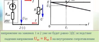
The main difference between a real and an ideal device is the presence of internal resistance . The higher this parameter, the closer the element is to the improved version. It follows from this that the voltage and power values are finite, that is, they have a certain operating range. At the same time, the system also has a limitation on the connected load. When solving problems, a real device is depicted as an ideal one, with an internal resistance connected in parallel.
Operation of this unit is possible at idle (without external load) due to the fact that we have a closed circuit due to internal resistance. The output current during this mode is reduced to zero. When connected short (short circuit mode), we get the maximum value, and the output voltage drops to 0.
As an example of such a device, let's look at the inductor . This provision is valid at the moment the circuit opens. So the potential difference in this mode increases sharply compared to the previous state. It's all about the EMF of self-induction that occurs in this element. When the voltage increases, the coil accumulates energy, and when it decreases, it releases it into the network.
Another example is the secondary winding of a current transformer , which should always be short-circuited under normal operating conditions. Otherwise, if a break occurs in it, it will become a generator. It's all about the law of conservation of energy, so the power on the primary and secondary windings should be the same. The parameters of the primary winding are unchanged due to the design features of the transformer (the winding has one turn). If there is a break in the secondary winding, there will be no ordered movement of charged particles, and accordingly the voltage will increase sharply.
Electrical voltage
Voltage is a physical quantity that characterizes an electric field.
Electrical voltage is denoted by the letter $U$.
Let's look at an experiment that will clearly show us how this quantity can describe the electric field to us.
Let's assemble an electrical circuit consisting of a key, a current source, an electric lamp and an ammeter. Let's take a small battery (galvanic cell) as the current source, and take an electric lamp from a flashlight (Figure 2).
Figure 2. Lamp glow from a battery-powered flashlight
Now let's assemble a similar chain. Let's replace the flashlight bulb with a large lamp for indoor lighting. We will also replace the battery. Now our current source is the city lighting network (Figure 3).
Figure 3. Glow of an indoor lamp from the city lighting network
Take a look at the ammeter readings in these two circuits. They are the same!
The current strength in the circuits is the same, but a large lamp gives much more light and heat than a small lamp from a flashlight. This is where our new quantity appears - tension.
Joule-Lenz law
Another task that can confuse even a more or less experienced student is to determine the current strength if the time, resistance and amount of heat generated by the conductor are known. To do this, remember the Joule-Lenz law.
As a conclusion, we propose to consolidate the information received on several examples of problems in which you need to find the current strength.
Task 1: Calculate I in a circuit of two resistors in a series connection and in a parallel connection. R 1 and 2 Ohm resistors, 12 Volt power supply.
It is clear from the condition that you need to give two answer options for each of the connection options. Then, to find the current in a series connection, first add up the resistances of the circuit to get the total.
When connecting two elements in parallel, R, the total can be calculated as follows:
Task 2: calculate the current for a mixed connection of elements. The output of the power supply is 24V, and the resistors are: R1=1 Ohm, R2=3 Ohm, R3=3 Ohm.
First of all, you need to find the common R of R2 and R3 connected in parallel, using the same formula that we used above.
Now you know how to find the current strength, knowing the power, resistance and voltage. We hope the formulas and calculation examples provided helped you understand the material!
Expert opinion
It-Technology, Electrical power and electronics specialist
Ask questions to the “Specialist for modernization of energy generation systems”
How to find current strength through power, resistance and voltage When calculating circuits and solving problems of finding the values of electrical parameters, it is necessary to use equivalent resistances. Ask, I'm in touch!
Relationship between current and voltage
Our experiments are explained as follows.
At the same current strength, the work done by the current in these sections of the circuit when moving an electric charge equal to $1 \space C$ is different.
It turns out that this work of current determines our new physical quantity - electrical voltage.
Now we can fully explain our experiments. The voltage created by the battery in the first circuit is less than the voltage of the city lighting network. Therefore, a lamp connected to the network provides more light and heat. In this case, the current strength in both circuits is the same. The whole reason for the differences is the tension created.
Voltage shows how much work an electric field does when moving a unit positive charge from one point to another.
Direct Current: Reviving an Old Technology
Today, 86 years after Edison's death, there are signs that the great inventor was not as wrong about direct current as people once believed. Edison's ideas are becoming relevant again as a number of recent developments make direct current more attractive.
Previously, electricity was produced by alternating current in generators of large coal or nuclear power plants, as well as in hydro turbines. They distribute energy through the AC network. Transformers allow voltage to be increased to several hundred thousand volts by holding current in cables. But now a number of electricity suppliers are moving towards using DC. These include, for example, solar power plants, which are usually supported by batteries or electrochemical storage systems. Converting DC to AC inevitably involves losses, making the DC grid the best choice for these suppliers.
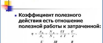
Formula for calculating voltage
If we know the work of the current $A$ in the section of the circuit under consideration and the entire electric charge $q$ that passed through it, then we can calculate the voltage $U$. In physical terms, we will determine the work of current when moving a unit electric charge.
$U = \frac{A}{q}$ Voltage is equal to the ratio of the work done by the current in a given section to the electric charge passing through this section.
From this formula we will also use two of its consequences:
$A = Uq$, $q = \frac{A}{U}$.
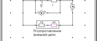
Calculation of mixed connection of resistors.
The calculation begins from the farthest section of the circuit in relation to the power source. Determine the area with a parallel or series connection of two resistors and calculate their total resistance Rtot
. Then the resulting resistance is added to a nearby resistor, etc.
number of elements in the circuit in order to simplify the circuit
and, accordingly, simplifying the calculation of total resistance.
Let's analyze a mixed connection circuit of seven resistors
The furthest part of the circuit turned out to be resistors R6
We calculate their total resistance using the parallel
Now if we compare the original circuit with the resulting one, here we see that it has decreased by one element and instead of two resistors R6 and R7, there is only one R6
Let's continue the calculation and the next far section of the circuit turned out to be resistors R5
We calculate their total resistance using the series
connections. The resistance of resistor R5 is 27 Ohms, and R6 = 30.709 kOhms, so for the convenience of calculating kilo-ohms, we convert kilo-ohms to Ohms (1 kOhm = 1000 Ohms):
The diagram decreased by one more element and took the form:
Now the far section turns out to be resistors R4
The original circuit has changed again and now consists of only four resistors connected in series
. Thus, we simplified the scheme as much as possible and brought it to a convenient calculation.
Now everything is simple. We add up the resistances of the remaining four resistors using the series
connections, and we get the total resistance of the entire circuit:
That's basically all I wanted to say about the mixed connection of resistors and the calculation of the mixed connection . Good luck!
Expert opinion
It-Technology, Electrical power and electronics specialist
Ask questions to the “Specialist for modernization of energy generation systems”
Ideal source of EMF If a circuit consists of several consumers, then when they are connected in parallel, the total current power in the entire circuit is equal to the sum of the powers of the individual consumers. Ask, I'm in touch!
Voltage unit
If the unit of current was named after the scientist, then we have the same story with the unit of voltage.
It is named volta in honor of the Italian scientist Alessandro Volta (Figure 4).
Figure 4. Alessandro Giuseppe Antonio Volta (1745 - 1827) - Italian physicist, chemist and physiologist, inventor of the galvanic cell
A unit of voltage is the electrical voltage at the ends of a conductor at which the work done to move an electric charge of $1 \space C along this conductor is equal to $1 \space J$: $1 \space V = 1 \frac{J}{C}$.
A Brief History of Electricity
Who invented electricity? And no one! People gradually understood what it was and how to use it.
It all started in the 7th century BC, on one sunny (or maybe rainy, who knows) day. Then the Greek philosopher Thales noticed that if you rub amber on wool, it will attract light objects.
Then there were Alexander the Great, wars, Christianity, the fall of the Roman Empire, wars, the fall of Byzantium, wars, the Middle Ages, the Crusades, epidemics, the Inquisition and more wars. As you understand, people had no time for any electricity or ebonite sticks rubbed with wool.
In what year was the word “electricity” invented? In 1600, the English naturalist William Gilbert decided to write the work “On the Magnet, Magnetic Bodies and the Great Magnet - the Earth.” It was then that the term “electricity” appeared.
One hundred and fifty years later, in 1747, Benjamin Franklin, whom we all love very much, created the first theory of electricity. He viewed this phenomenon as a fluid or immaterial liquid.
It was Franklin who introduced the concept of positive and negative charges (before that, glass and resin electricity were separated), invented the lightning rod and proved that lightning is electrical in nature.
Everyone loves Benjamin, because his portrait is on every hundred dollar bill. In addition to his work in the exact sciences, he was a prominent political figure. But contrary to popular belief, Franklin was not the President of the United States.
Next will be a list of discoveries important for the history of electricity.
1785 - Coulomb finds out with what force opposite charges attract and like charges repel.
1791 - Luigi Galvani accidentally noticed that the legs of a dead frog contracted under the influence of electricity.
The operating principle of the battery is based on galvanic cells. But who created the first galvanic cell? Based on Galvani's discovery, another Italian physicist Alessandro Volta created the Volta column in 1800, the prototype of the modern battery.
At excavations near Baghdad, they found a battery more than two thousand years old. What ancient iPhone was recharged with its help remains a mystery. But we know for sure that the battery has already run out. This case seems to say: maybe people knew about electricity much earlier, but then something went wrong.
Already in the 19th century, Oersted, Ampere, Ohm, Thomson and Maxwell made a real revolution. Electromagnetism was discovered, induced emf, electrical and magnetic phenomena were linked into a single system and described by fundamental equations.
By the way! If you don’t have time to deal with all this yourself, our readers are now offering a 10% discount on any type of work
The 20th century brought quantum electrodynamics and the theory of weak interactions, as well as electric cars and ubiquitous power lines. By the way, the famous Tesla electric car runs on direct current.
Of course, this is a very brief history of electricity, and we have not mentioned very many names that influenced progress in this field. Otherwise, a whole multi-volume reference book would have to be written.
Voltage value for some devices and natural phenomena
Table 1 provides some voltage values for your reference.
| Device | $U$, $B$ |
| Galvanic cell | 1,25 |
| City power grid | 220 |
| Electric lamps | 20 — 250 |
| TV | 100 — 600 |
| Fridge | 150 — 600 |
| Computer | 400 — 750 |
| Iron | 500 — 2000 |
| Electric motors | 550 — 1700 |
| Heater | 1000 — 2400 |
| Air conditioner | 1000 — 3000 |
| A circular saw | 1800 — 2100 |
| High pressure pump | 2000 — 2900 |
| High-voltage power lines (PTL) | 500 000 |
| Lightning strike | Up to 1,000,000 |
Table 1. Voltage in some technical devices and nature
Dangerous and safe voltage values
Everyone knows that high (high) voltage is life-threatening. Let's make a simple analogy for better understanding.
For example, the voltage between a high-voltage transmission line wire and ground is $100 \space 000 \space V$. Let's connect this wire to ground. It turns out that when a charge of only $1 \space K$ passes through it, work of $100 \space 000 \space J$ is done. The same work will be done by a load weighing $1000 \space kg$ if it falls from a height of $10 \space m$. Similar damage can be caused by high voltage.
Typically, a voltage of no more than $42 \space V$ is considered safe . Such voltage is created, for example, by galvanic cells.
Many people probably remember how, as a child, their parents forbade putting their fingers into a socket. And it’s better not to disassemble it yourself. It is better to entrust such work to specialists. Why? The current in such a network comes from generators, and the voltage is usually $220 \space V$. Such tension can cause significant harm to health.