When it comes to transformers and their types, all models still have similar functionality; the only way transformers can differ from each other is the scope of application and the materials chosen to complete the product. In the assortment of power elements, the toroidal transformer, characterized by successful design capabilities and good performance, takes pride of place. And the most important difference between a toroidal transformer and all other types is that the core or magnetic circuit of the product is formed in the form of a ring. However, we will consider all other technical advantages and areas of application further in more detail in the article.
What are the purpose and functionality of toroidal transformers?
- power and measuring;
- increasing or decreasing.
Such power elements are capable of converting electricity, affecting voltage or current to varying degrees.
Where and for what is a toroidal transformer used?
The power toroidal transformer has a wide range of applications, both in industrial and domestic environments. So, many ordinary people don’t think about it, but toroidal transformers literally surround us, providing us with comfort and coziness in our houses and apartments. Firstly, low-frequency transformers are involved in the formation of the power system and all major communications, not excluding ordinary sockets. Secondly, in the circuits of an uninterruptible power supply for a computer and smartphone, you can also find a transformer, which is considered an indispensable element of the circuit.
And in the field of radio engineering, electronics, and engineering one cannot do without toroidal transformers. It is obvious that such important power elements are used to create a safe and efficient power source for lighting equipment and the operation of modern medical and diagnostic equipment.
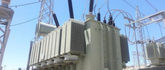
In an industrial environment, a toroidal transformer is calculated and implemented in the configuration of welding equipment circuits.
Notes
- “What makes toroidal coil transformers different from other transformers? | Blog about custom reels." Custom Reels Blog
. Retrieved 2018-04-03. - "Toroidal Transformers - Agile Magnetics, Inc." Agile Magnetics,
Inc. Retrieved 2018-04-03. - "How does a toroidal transformer work?" The science
. Retrieved 2018-04-03. - ^ a b
Griffiths (1989, para. 222) - Reitz, Milford and Christie (1993, para. 244)
- ^ a b
Holliday and Resnick (1962), para. 859) - Haight (1989), para. 231)
- Feynman (1964, para. 14_1-14_10) harvtxt error: no target: CITEREFFeynman1964 (help)
- Feynman (1964, para. 15_1-15_16) harvtxt error: no target: CITEREFFeynman1964 (help)
- Feynman (1964, para. 15_11) harvtxt error: no target: CITEREFFeynman1964 (help)
- ^ a b
Feynman (1964, para. 15_15) harvtxt error: no target: CITEREFFeynman1964 (help) - Purcell (1963), para. 249) harvtxt error: no target: CITEREFPurcell1963 (help)
What technical advantages do toroidal transformers have?
- Cost-effective performance of a power element with a ring magnetic core. Internally, power transmission occurs with smaller size and weight.
- Compactness and small volumes of the product. That is, winding a toroidal transformer performs its task without failure, but the transformer itself is half the size compared to other models.
- Easy to install and operate. Undoubtedly, transformers with a ring core are very easy to install in the position specified according to the circuit, connect, and test before the first operational start-up. And it doesn’t matter where the installation is planned - inside or outside.
- Saving electrical impulse. About a third of the energy produced is retained both at full load and at idle.
- High thermal load capacity. The shape of the magnetic circuit – a toroid – contributes.
With so many technical advantages, the toroidal transformer wins in many respects. For example, compared to armored and rod transformers, it has low dissipation rates, therefore it is safe and simply indispensable for sensitive electronic equipment.
Content
- 1 Advantages of toroidal windings
- 2 Complete limitation of field B by toroidal inductors 2.1 Sufficient conditions for complete internal confinement of field B
- 2.2 E field in the plane of the toroid
- 2.3 Toroidal inductor/transformer and vector magnetic potential
- 2.4 Toroidal action of a transformer in the presence of full field limitation B
- 2.5 Toroidal transformer Poynting vector connection from primary to secondary in the presence of full field limitation B 2.5.1 Explanation of the figure
What are the advantages of a toroidal transformer core?
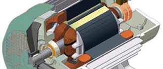
Recall that the core or magnetic circuit of the toroidal transformer 220 is manufactured in the form of a ring. And this is almost an ideal form in physical terms. For its production, tape-shaped permalloy is most often used in production, and the material consumption is small, and rejection and trimming on the conveyor is reduced. At the second stage of the sequential manufacturing of the transformer, a winding is applied to its core and distributed evenly without flaws over a given surface. The length of the winding wires is short, so the resistance force in the segment is also reduced. And this provides the toroidal transformer with high efficiency. The core of the toroidal transformer itself plays an important role in this.
What is a transformer?
Un transformer This is an element that allows you to change from alternating current voltage to another. It can also convert current. In any case, it will always keep the frequency and signal strength constant. That is, isofrequency and isopower...
This last parameter is incorrect, it would be in an ideal theoretical converter, since in practice there is loss in the form of heat , one of the biggest problems of these components. That's why he switched from using solid iron cores to laminating them (sheets of silicon steel with insulation between them) to reduce eddy currents, or stray currents.
To achieve its purpose, the electricity supplied through the input winding is converted into magnetism by the winding and the metal core. The magnetism flowing through the metal core will then induce a current or electromagnetic force in the secondary winding to produce a specified current at its output. Of course, the conductive wire of the windings has a kind of insulating varnish, so although they are wound, they are not in contact with each other.
To convert one voltage to another, you need to play with the number of turns or turns of copper wire in the primary and secondary windings. According to Lenz's Law , the current must be alternating for such a change in magnetic flux to occur, so a transformer cannot operate with direct current.
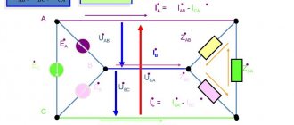
As you can see in the image above, the relationship between the coils voltage and intensity is very simple. Where N is the number of turns of the winding (P = primary, S = secondary) and V is the voltage (P = applied to the primary winding, S = output of the secondary winding) or I equal to the current...
As an example, Imagine you have a transformer with 200 coils in the primary and 100 coils in the secondary. An input voltage of 200 V is supplied to it. What voltage will appear at the output of the secondary? Very simple:
200/100 = 220/V
2 = 220 / V
v = 220/2
v = 110 V
That is, it converts 220V input to 110V output. But if the number of turns in the primary and secondary windings are reversed, the opposite will happen. For example, imagine that the same primary voltage of 220 V is applied to the primary winding, but the primary winding has 100 turns and the secondary winding has 200 turns. To invest this:
100/200 = 220/V
0.5 = 220 / V
v = 220/0.5
v = 440 V
As you can see, in this case the voltage doubles...
What must be taken into account when calculating a toroidal transformer
In order to apply the standard physical formula, you first need to know the parameters of the voltage that will be supplied to the primary winding of the product (symbol for the formula - U), the outer and inner diameter of the core or magnetic circuit (symbol for calculations - D and d), and, The main thing is not to forget about the thickness of the magnetic circuit - H.
An important indicator is the area of the core window (previously recorded in the records - S). The intensity of excess heat removal largely depends on it. These core gap areas range from 80 to 100 cm, and the cross-section is half as large.
Just in case, let us remember the calculation formulas in the article: S0 = * d2 / 4., Sc = H * (D – d)/2.
Price overview
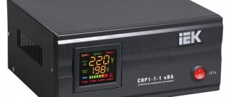
You can buy a toroidal transformer HBL-200 in any city in the Russian Federation and CIS countries. It is used for various audio equipment. Let's look at how much the converter costs.
Fedotov Alexey Gennadievich (UA3VFS) Gus-Khrustalny
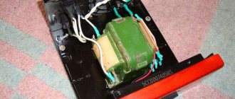
The winding technology and the insulation method are actually very simple and in no case involve any kind of winding, varnished fabric, or anything else. The fact is that with any winding with varnished cloth or other insulators, the internal window of the TORA is instantly filled, since on the outside there is one layer, and on the inside there are 5-10 layers, and even uneven ones. I have long been planning to write an article about a method for high-quality winding of tori. This takes quite a long time to explain and is better shown in the photo. Moreover, after winding, the windings do not turn into a wheel, and the transformer itself does not become egg-shaped and wire consumption is minimal. In view of all this, the efficiency of the transformer is maximum. And what comes out of this, you can see in my amplifier.
Let me make a reservation right away: we are talking about powerful toroidal transformers. Overall power, which is more than 500W. Which are wound with wires from 1 to 3mm. naturally turn to turn. And, as a rule, the network winding of which lies in the range from 100 to 400 turns, in total, that is, 0.5-2 turns per volt. Winding less powerful transformers in this way is troublesome, but it is possible if desired.
What is needed for winding.
1) You need to make a stand for winding the toroid; this is done very simply. Take a square piece of chipboard or plywood 10-15mm thick. With dimensions of 200X200mm, we also need two wooden blocks 200mm long and 20X20mm square. We need to either glue these two bars in the center of our site, parallel to each other, with a distance of 100mm between them. It’s even better to screw these bars to the platform using screws, but with countersunk heads and recess the heads into the plywood, otherwise they will scratch the table. Now if you put a toroid on this stand, it will stand firmly and steadily. 2) You need a shuttle, I cut the shuttle out of plexiglass 5-6mm thick. The width is usually 30-40mm. length 300-400mm. I make the end cuts not at an angle, but in a semicircle and process them with a file so that the insulation of the wire does not deteriorate, and I even glue one or two strips of electrical tape, again to protect the wire. We wind the wire onto the shuttle; it’s okay if there isn’t enough wire, you can carefully solder the wire and wind it further. But it’s better to calculate it so that there is enough wire. 3) Now we need material for insulation between the layers, it’s very simple, you just need to find thin cardboard (packaging), for example, I use speaker boxes for cars. The main thing is that it is not a thick, but not thin material, the thickness of the cardboard is about 0.5 mm. If it is glossy on one side, then that is also good. 4) We also need thick threads, number 10-20. But at worst, number 40 is possible. The winding itself is carried out away from you to the right.
And now the most important thing is the manufacture of the insulating gaskets themselves between the layers. We will need a caliper with sharp ends.
We measure the outer diameter of our torus and add 20mm. (for overlap) and divide in half. For example, the outer diameter of the torus is 150mm + 20mm = 170mm. 170mm./2 = 85mm. We set the bar to 85mm. and fix it with a screw. We will use the rod itself as a compass for drawing circles on cardboard. Why use a barbell and not a regular compass, which is both easier and more convenient? And everything is very simple, when we draw on the cardboard with the sharp and durable end of the rod, a depressed groove will remain on the cardboard and it will help us. This groove is very useful for making it easier to bend the inner cut circle of our gaskets. In general, you yourself will understand that a barbell is better than a convenient compass. And so we draw the outer circle on the cardboard and cut it out with scissors; in principle, the outer circle can be drawn with an ordinary compass. Next, we measure the internal diameter of the torus, do not add or subtract anything, but simply divide it in half.
For example, diameter 60mm/2 = 30mm. We set the caliper caliper to 30mm. fix it with a screw and draw the internal diameter on cardboard. Next, we take a pencil and a ruler and work on the inner circle, first we draw a cross, that is, we divide the circle into 4 parts, then into 8 parts, if the inner diameter of the TOR is more than 60mm. then also into 16 parts. >Next, we draw another circle with a regular compass, which is half the size of the inner one, that is, we move the compass apart by 15mm. And now we need a flat piece of plywood or chipboard on which we will place our cardboard blank for cutting through our parts drawn in pencil with the end of a sharp scalpel or knife. You need to cut in a circle from the outer edge of the circle to the central point, no further, otherwise the cardboard will ride up. You need to cut right through the cardboard. Next, using scissors, we cut out the inner circle we drew with a regular compass. Bend the resulting slices perpendicular to the workpiece. It is clear that two such blanks are needed for each layer; each time the diameters are measured again, since their value changes from layer to layer. Next, measure the height of the torus and cut out two strips of cardboard of the same width. We insert one strip inside the torus, so that the overlap is no more than 10mm. We wind the second strip in one layer onto the outer side of the torus with the same overlap. We put both round blanks on the ends of the torus, fasten them with thread in three or four places in a circle. And then we begin to wind.
Is it possible to make a toroidal core yourself?
A geometrically correct toroidal core is not so easy to reproduce independently, especially by novice inventors. Firstly, you need to have at your disposal a special permalloy tape, also sometimes called transformer steel. Secondly, familiarize yourself with the rules for forming a torus of rectangular cross-section. The actions are familiar - you need to roll the material into a roll. Actions are consistent and careful, if necessary, go back a step.
A special wooden shuttle with technical semicircular cutouts can be a help in this matter, especially if you need to calculate how much material is needed for winding. The wire for the winding is always taken with an allowance. Recommended reserve is 20-30%.
Thus, it becomes clear that a toroidal transformer can give a head start to other existing power elements. And all because it is simple, reliable and functional. The existing core is created in an advantageous form, which is easy to work with not only at the stage of product manufacture, but also during installation, operation and repair. It is possible to make such a transformer yourself, but this will require perseverance, knowledge, the desire to create a product, the desire to make calculations and look for alternatives.