Grounding in the understanding of ordinary people is a pin or a group of metal corners (circuit) driven into the thickness of the soil. Why is he driven in? Surely everyone knows that for protection by connecting it to the housings of electrical appliances on which a phase may appear in an emergency. And then many people’s knowledge is mixed into a picture created from fragments of quotes and incorrect interpretations.
The topic of grounding is very important and broad. Therefore, to understand how grounding works, we will try to consider all the processes clearly with an explanation in words that are easy for ordinary people (not electricians) to understand.
Main goals and objectives of grounding
Grounding consists of a ground electrode and grounding conductors through which the current flows into the soil and is neutralized.
The soil is capable of neutralizing electric current, since its voltage level is zero. Resistance is the main indicator of a grounding device, by which one can judge its quality and ability to fulfill its purpose. The resistivity depends on the composition of the soil, the presence of chemicals in it - acidic or alkaline, humidity, and looseness. Depending on the composition of the soil, it may be necessary to use some special grounding kit or completely replace the soil for the correct operation of grounding devices.
Grounding is the connection of any device, electrical installation or part of the network to a grounding device. It consists of a grounding conductor and grounding conductors through which the current flows into the ground and is neutralized.
There can be several grounding electrodes. In a distributed scheme, they are located along the perimeter of the facility, the electrical network of which must be secured. The conductive part (grounding conductors) is usually made of metal. Grounding electrodes are connected to them, which have direct contact with the soil.
Ground loop device
The grounding device is mounted along the contour. The ground loop is several electrode conductors that are driven into the ground. Their length is 3 meters, they are located at a short distance from each other. A horizontal metal strip is used as a connection, which is laid in the soil to a shallow depth - up to 1 meter. The connection to the electrodes is made using conventional welding. In special grounding kits, parts of the equipment are connected with threads, which does not in any way affect the operating properties.
Working grounding is necessary in the following cases:
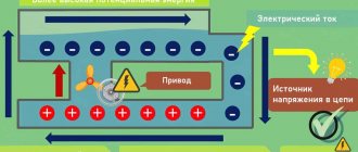
- Protecting equipment from the accumulation of static electricity. Natural processes, such as lightning, can affect the current flowing in a circuit, resulting in equipment damage. Electrodes installed in the ground drain excess current.
- Network protection against short circuits.
- Overvoltage protection.
An example of working grounding is a lightning rod that is connected to the electrodes. Especially relevant in generators and transformers.
Electrical installation Ivanovo - Zeroing: will it protect or kill?
Zeroing – will it protect or kill?
Hello, friends!
In this article we will talk about what zeroing is, where it is used, as well as the main errors in its design. The topic is not easy, and there are constant debates on forums.
It is interesting that often even electricians cannot correctly say how grounding differs from grounding. Let's figure it out. First, let's see what the PUE says about zeroing.
Simply put, grounding is the connection of the body of an electrical device with the neutral wire.
Now let's see what the PUE tells us about grounding
note
Grounding of any part of an electrical installation or other installation is the intentional electrical connection of this part to a grounding device.
In simple words, grounding is the connection of the body of an electrical device with a ground electrode. A ground electrode is a structure made of metal pins driven into the ground.
Now let's look at how the most common power supply systems for apartment buildings work.
Old, Soviet TN-C system
More modern TN-CS system
Both schemes use a combined neutral conductor PEN, which is grounded at the transformer substation.
The main difference between them is that in TN-CS the combined conductor is divided into a working zero and a protective conductor. This is done in the introductory common building panel (ACB). In this case, re-grounding must be done.
If you look closely at the diagrams, it becomes clear that the working zero is always connected to ground, that is, grounded. And the question arises: what, exactly, is the difference between grounding and grounding? After all, by connecting the body of the device to the working zero, we actually connect it to the ground.
In fact, there is a difference. It lies in the principle of action.
Grounding is designed to drain current to ground. This reduces the dangerous voltage on the body of the device or device.
Grounding is intended to create a short circuit effect during phase breakdown on the housing. At the same time, the machine is activated and turns off the emergency line.
Important
Thus, grounding and grounding in TN systems work simultaneously, so to speak, in one bottle. Therefore, the 3rd protective contact in Euro sockets in TN systems is both grounding and neutralizing.
Based on this, it is correct to talk about a combined conductor PEN, a working neutral conductor N and a protective conductor PE. At the same time, even electricians do not always understand the difference between PE and N, but it is very significant.
Usually, when some “electrician Uncle Vasya” talks about grounding, he means various kinds of collective farms such as jumpers in sockets and the like connecting the protective wire to the neutral wire. And it's dangerous.
Incorrect zeroing can, instead of protection, cause a tragedy. And such pseudo-protection occurs very, very often.
Let's figure out how protective grounding is done correctly and what absolutely should not be done.
Remember, the division of the combined conductor into a working zero and a protective zero must be done in a common house input device (IDU). And from there the protective conductor must go to the floor panels, and from them to each apartment.
Thus, we get a five-wire riser: 3 phases, working zero and protective zero. In this case, we are not talking about the so-called grounding, since each apartment receives a separate protective wire (TN-CS and TN-S systems). It needs to be connected to the third contact of the sockets.
In old houses with non-modernized wiring, there is usually a four-wire riser: 3 phases and a combined neutral PEN (TN-C system). This is where the complete chaos and terrible mistakes begin.
Advice
It all starts in the floor panel. Often it makes an independent division of PEN into PE and N.
This option has the right to life, but only if important rules are observed. Here are the main ones:
Rule 1. In single-phase circuits, it is prohibited to separate the neutral wire (PUE - 1.7.132).
How to determine which network is in your home? In relatively old houses, the access risers are four-wire: three phases and one combined neutral (PEN). That is, three-phase risers are used, respectively a three-phase circuit.
In very old houses, Stalin and Khrushchev buildings, a two-wire riser is often used, in which there is only a phase and a working zero. A distinctive feature of such houses is the absence of access panels. The risers go in the shafts between the apartments, and in the apartments themselves there are specific “humpbacked” shields. In such houses, as a rule, a single-phase network is used.
Rule 2. The combined PEN conductor must have a cross-section of at least 16 mm for aluminum or 10 mm for copper.
That is, the zero riser must have a cross-section no less than the specified one. In many houses the cross-section is smaller; in this case, it is impossible to divide the combined zero into protective and working. If you have a Soviet-built house with gas stoves, then in 80% of cases the riser in it is weak.
Rule 3: Once PEN is split into PE and N, they cannot be reconnected.
Here, I think, no explanation is needed.
Rule 4. The protective conductor PE must not be disconnected.
That is, you cannot install machine guns and other disconnecting devices on it.
Rule 5. PEN must be separated BEFORE all machines, switches, switches.
It’s better to do this: take a brass busbar and screw it to the shield so that there is contact between them. Make a branch from the zero riser through a separate nut to this bus. Connect the PE protective wires from the apartments to the bus.
If at least one of these rules is not followed, then it will not be protection, but a life-threatening collective farm.
A little more about what not to do
1) Connect the protective and neutral contacts in the socket with a jumper. This is one of the most dangerous mistakes!
note
If the zero burns out, is damaged, or is accidentally disconnected, dangerous phase voltage will immediately appear on the housing of all devices connected to such sockets. In this case, neither the RCD nor the machine will work. Hello death.
The same effect will occur with a random change of phase and zero.
2) Place the neutral and protective conductors on one screw in the shield
PE and N must be on different terminals (busbars). Moreover, each wire from a separate apartment must be clamped with a separate screw.
3) Zero to an ungrounded (non-zeroed) shield.
Typically, all panels have direct contact with the zero or protective riser (zeroed). But sometimes there is no contact, for various reasons. For example, the connecting wire fell off. Grounding such a shield can lead to the appearance of dangerous voltage on its body.
In practice, this kind of jambs are found all the time, in various variants and combinations. I can advise you not to be lazy, study the PUE, and also not trust your wiring to dubious individuals.
Source: https://elektro.ivmast.ru/zanulenie-zashchitit-ili-ubet
Protective grounding principle
Protective grounding is a set of measures that are aimed at protecting equipment and people who work with it. Used to eliminate electromagnetic interference arising from a device operating nearby, as well as to neutralize interference during switching in the power circuit.
Lightning protection
Scheme for protecting a house from lightning
The air is an area with high resistance, but the discharge has a power that exceeds this resistance, so it breaks through it. Along its path from the upper atmosphere to the ground, lightning selects areas with the least resistance - wet areas, walls, trees and water drops. This explains the fact that discharges often hit wood - it has less resistance than the air around it. When current enters a building, it also passes through areas with the least resistance - these are metal pipes, electrical appliances or their metal parts, and damp walls. If the device is not grounded, touching it while a charge is passing through can be fatal.
When installing a lightning rod on the roof, the charge enters it, and then moves to the ground and is neutralized. It is important that currents do not spread inside the object, so the materials used for grounding have low resistance. According to the rules, it should not exceed 4 ohms. The lightning rod itself must be connected to electrodes in the ground.
Surge protection
Surge protection devices
Electronic equipment is sensitive to power surges or powerful electrical installations operating within their radius. A sudden lightning strike nearby can damage electronics.
As an example: during a thunderstorm, an excess charge can occur in the copper cable that connects houses and carries current. The charge, when its size increases, can destroy the cable. In this case, an SPD is installed on the power line - a surge protection device so that the excess charge is discharged into the ground.
Protecting people
Device housings and all metal elements are capable of conducting current. If you touch an ungrounded device that has accumulated static electricity, you may receive a severe shock. This will affect primarily the cardiovascular and nervous system. Rubber shoes, rubberized gloves, and a completely dry room help reduce the impact, but people rarely walk around an apartment or office in rubber boots. Connecting the third wire to the body of the devices, and then connecting it to the electrodes, allows you to dispose of excess current into the ground.
In old private and apartment buildings, grounding measures were not carried out, so all electrical appliances pose a potential danger to people.
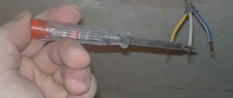
Homemade devices may look like this: a wire is connected to the body of the device, which is led out into the street and connected to a metal product driven into the ground (pipe, corner, bucket, fittings). These products are good conductors of current, unlike the human body, so the current selects the metal and goes into the ground.
Features and Differences
Grounding has a wide range of purposes, and the main principle of protective grounding is the drainage of electric current into the ground from the metal surfaces of electrical appliances. Let's consider for what purposes is protective grounding used and what are the differences from conventional grounding?
The main function of conventional, so-called working grounding is to protect electrical appliances from unstable operation and failures, as well as to prevent emergency situations such as short circuits.
The main function of PROTECTIVE GROUNDING is to protect a person in the event of an emergency when there is a high probability of electric shock when coming into contact with metal parts of electrical appliances.
In addition, this type of connection:
- complies with the PUE regulations (rules for electrical installations);
- reduces interference during the operation of electrical equipment;
- is an excellent lightning protection for a building.
In a modern house/apartment, it is simply necessary to carry out work on laying a grounding cable and connecting it to the common “ground circuit”. This is due to the fact that modern household appliances have serious power indicators, they are capable of consuming large amounts of energy, and their body parts are usually made of metals that are known to conduct electric current well. The absence of a grounding circuit can have serious consequences, especially when installing equipment such as:
- washing machines;
- refrigerators;
- electric stoves;
- water heaters and boilers;
- microwaves.
Direct connection through such a circuit allows you to avoid the appearance of high voltage on the surfaces of these electrical appliances and reduce the amount of interference that occurs during the operation of this equipment.
The difference between working grounding and protective grounding
According to safety regulations, working and protective grounding should not be combined with a water circuit. During atmospheric discharges, electrical devices may be damaged, and the protective grounding will not work.
In the functional (working) grounding scheme, all current-carrying structures are connected to electrodes installed in the ground. For the correct operation of working grounding, fuses are also used, which absorb the voltage and fail.
Working grounding is provided if the devices are accompanied by manufacturer's instructions and requirements that protect the device.
More requirements are placed on the protective grounding device, since it has more important tasks: preserving people’s lives.
| Purpose of a working grounding device | Purpose of protective grounding |
| High power of devices | Three-phase devices with power less than 1 kW |
| Electronic sensitive equipment | Single- and two-phase devices without contact with the ground |
| Medical devices | Equipment with a power of more than 1 kW |
| Electronic equipment that carries important information | In circuits with fuses and neutral protective conductor |
The most reliable grounding is provided in the electrical circuit of the house. The cables that go to each outlet must be three-conductor. The third wire connects to the ground and removes static electricity, and also prevents short circuits and lightning from entering the building.
How to install an artificial electrode in the ground
During the manufacturing process, the artificial grounding conductor is repeatedly tested for compliance with all parameters of regulatory requirements. The situation is similar with its installation and location in the ground. Summarizing the data, we can highlight the main points of the production of such electrical installation:
- The installation process is almost completely mechanized.
- If two extended (horizontal) beams are provided, the electrodes are laid from the grounded part of the electrical installation in opposite directions. Provided that there are more than two ground electrodes, the beams are laid at an angle (angle 120° - 90°). This placement is due to the improvement in the resistance indicator.
- When installing a ground electrode, potential distribution often occurs. The difference in potential on the surface of the soil (above the ground electrode) and around the element (inside the soil) causes dangerous voltages to arise. To equalize potentials in such cases, an artificial ground electrode is made in the form of a grid. Horizontal electrodes are laid both along and across the electrical installation area. Connections at intersections are made by welding.
Important! When electrodes of this type are placed close together, shielding occurs. Their effectiveness rate decreases.
The final stage of grounding will necessarily be the work of measuring grounding resistance parameters.
Requirements for protective grounding
In order for grounding installations to perform their functions, they must comply with certain parameters and instructions from the equipment manufacturer.
Nuances that affect functionality:
- Soil resistance due to its physical and chemical characteristics. The best conductors of current are wet clay, graphite chips, peat, salt marshes or sea water. Worse - dry sand or hard rocks - granite, crushed stone, quartz, asphalt, concrete.
- Contact area of the ground electrode with the soil. The larger the area, the more favorable conditions are created for the flow of current, the faster this happens. You can increase the area by installing more electrodes along the contour of the building. In this case, they are connected together with a steel plate into a single unit. If you increase the size of one electrode, the total area will also increase. Installing a vertical metal contour helps to increase the area if the lower layers of the soil have greater resistance than the surface ones.
Since it is difficult to achieve ideal soil resistance, devices are created based on its characteristics. Each electrical installation has its own standards for the resistance of grounding devices. For example, for an electrical substation with a voltage of more than 100 kW, the resistance should not be more than 0.5 Ohm, and for a home network with a TT system, as well as the use of automatic shutdown, up to 500 Ohm.
It is necessary to treat grounding welds against corrosion.
Metal grounding conductors should not be coated with paints and varnishes. Sometimes the underground part of a building with metal structures is used as a grounding device - electrically conductive concrete with reinforcement inside. Gas metal pipes cannot be used to solve the grounding problem.
According to the Electrical Installation Rules, the following are subject to grounding:
- Networks whose voltage is higher than 380 V.
- Particularly dangerous and outdoor installations.
Parts of equipment subject to grounding and grounding:
- Electrical equipment housings.
- Secondary transformer winding.
- Drives of electrical devices.
- Distribution boards, cabinet frames.
- Metal structures of equipment.
- Iron cable sheath.
If the voltage does not exceed 42 VAC or 110 VDC, grounding is not required.
Main parts of the structure
The system is a device with a simple design consisting of the following elements:
The pins are a frame used to connect the grounding terminals of equipment to the corresponding bus and act as conductors of electrical energy. As a rule, they are driven into the ground to a depth of 2 to 3 meters. Together with the bus, the pins form the so-called metal connection.
Metal bonding is a mandatory element located in any residential building, which is an iron welded structure connecting the upper ends of the ground electrodes to each other. She is taken to the entrance panel of the house for further distribution to apartments.
In accordance with Appendix 3, clause 26 of PTEEP rules for the technical operation of consumer electrical installations, the measurement of metal bond resistance is carried out at the following frequency:
- more than once every 12 years for supporting structures of overhead lines (OHL) with voltages over 1 kV and more than once every 6 years for overhead lines up to 1 kV;
- more than once every 12 years in accordance with the schedule of planned preventive maintenance (PPR).
To carry out the measurement, the grounding terminals of the electrical installation and the most distant ground loop are used . The resistance is checked at each section of the line and the value of this parameter at each section should not be more than 0.1 Ohm.
Artificial grounding: types, functions, requirements and installation
When the device of artificial ground electrodes is placed on arable land, all electrodes must be placed at a depth of at least 1 meter. This allows for increased contact with the ground.
Expert opinion
Viktor Pavlovich Strebizh, lighting and electrical expert
Any questions ask me, I will help!
All these average resistance values correspond to normal standard soils, the resistivity of which does not exceed 100 Ohm x m. If something is not clear to you, write to me!
Household grounding
Grounding a bathtub in an apartment
Most accidents in domestic conditions are associated with touching a device that has damaged insulation. The human body in this case is a conductor of current. Electric cookers, washing machines and dishwashers, heating radiators, microwave ovens, boilers, PCs, dishwashers - all these are metal structures that conduct current well and without grounding can cause harm to health.
A short circuit is the contact of the phase and neutral wires in the network, which leads to emergency protection and disconnection of the device from the power supply. Most often, it is not a short circuit that occurs, but a leakage of current that accumulates in the housing of household equipment. This may result in electrical shock.
For human safety, it is necessary to install sockets with grounding contacts. A three-wire cable must be connected to the outlet. With a two-wire and three-wire system, grounding is equipped differently - from the distribution box or electrical panel.
Gas, water or central heating pipes cannot be used as a grounding conductor.
The concept of zeroing
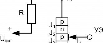
Grounding can be called the connection of individual metal parts that are not under the influence of direct voltage, either with the grounded neutral of a step-down three-phase current source, or with a grounded single-phase current generator. Thus, high voltage surges will be diverted to a transformer or to a separate panel for absorption. Typically, grounding is done in electrical installations with a grounded neutral. It allows, in the event of a breakdown of the insulating layer on the wire and a short circuit, to quickly operate a circuit breaker or respond to other protective equipment.
Quite often, additional residual current devices are installed. They will operate at different current strengths in phase and “zero” of the power wire. Such equipment can be installed together with a circuit breaker. In this case, after a breakdown of the core, both devices may operate simultaneously, or a faster-acting element may operate.
Typically, grounding is applied according to the rules for constructing electrical installations for industrial equipment. This type of protection does not guarantee the safety of the building. If the damaged phase gets to the outer part of the device, then the current will not go anywhere. Subsequently, two phases will be paired at once, which leads to a short circuit in the electrical network. Grounding does not create protection against current for a person. Conventionally, this is a specific indicator of a malfunction or damage to the power line, which prevents fire in the event of a short circuit.
In residential buildings and apartments it is not at all necessary to do zeroing, since this, on the contrary, can have a number of negative consequences. For example, if the neutral core in the cable burns out, then most household equipment and appliances will also burn out. This is due to a sharp surge in high voltage in the electrical network.
Grounding operation in case of electrical equipment faults
Equipment malfunction means damage to the insulation and the occurrence of a phase in the device housing. If parts of the equipment are energized, but are not protected by grounding and RCD, a person unaware of the danger may receive an electric shock.
In the second option, the current leakage may not be significant; the equipment protection device will not react to the voltage and will not turn off the device. The person may receive a minor blow.
If the housing is not grounded, but the RCD is installed, it will operate 0.02 seconds after a person touches the device body. This time is not enough to cause harm to health.
The most effective scheme from a safety point of view is the presence of grounding and an RCD. If a current leak occurs and passes into the ground, the RCD reacts and turns off the device.
Arrangement of protective current taps when working with three-phase electrical equipment
Switching three-phase electricity consumers differs from connecting conventional household electrical equipment, therefore the installation of protective systems is carried out in a different way. In this case, you should not confuse the neutral or ground wire involved in the control system, that is, involved in the start-up and stop circuit of the unit, with the protective conductor designed to divert a dangerous discharge to the ground.
Design, wiring, connection of electrical equipment
The work is carried out in several stages:
- A separate line (route) is installed along the perimeter of the room, made of a narrow metal strip 40x3 mm or copper wire with a cross-section of 16 mm2.
- A busbar (preferably copper) with contact devices (studs or holes for bolted connections) is mounted on it in a hidden place. It is possible to use a metal bus, but in this case welding the studs is a prerequisite.
- This line is connected to a grounding or grounding circuit, which is led out by a separate wire from the switchboard and has a reliable connection to the ground either directly or through a working zero
- The housings of all consumers (three-phase electric motors) are connected via a copper wire to the described bus.
If a short circuit occurs from a voltage leak due to an insulation failure or a “breakthrough” of one of the phases onto the body of grounded electrical equipment, the current will immediately flow into the ground along the path of least resistance, that is, through the conductor connected to the working zero or ground. This will protect a person from electric shock when touching the body of the device.
A grounding device is allowed only if it is not possible to switch with the ground loop. In all other cases, only protective grounding is considered correct.
The unit is connected through a copper wire to a bus mounted from the grounding path
Mandatory use of additional protective devices
The described grounding and neutralizing systems are effective when significant leaks or short circuits occur on the housing of electrical appliances. However, to achieve complete safety when servicing equipment, it is necessary to use additional means of protection to ensure that the electrical circuit is broken when malfunctions occur.
At manufacturing enterprises, these can be automation units (insulation monitoring of BKI or maximum current protection). But the most common means, both in production and in everyday life, are circuit breakers and residual current devices, which:
- will ensure that the electrical circuit is de-energized in case of problems;
- protect the user from electric shock;
- will protect equipment from fire.
Such devices can be designed for single-phase or three-phase systems. They are:
- single-pole - installed on one of the lines (zero, phase);
- bipolar - installed on both wires of the electrical wiring;
- multi-pole (three or more) – used for three-phase voltage.
Household wiring diagram with PE grounding conductor and VA and RCD protection
The circuit breaker switches off when the current load exceeds the rated value indicated on the device body. The RCD monitors the state of the electrical network and is triggered when the slightest current leakage occurs.
How to calculate the parameters of the main grounding elements
The parameters of the grounding device are calculated using formulas. The starting elements are:
- soil resistance in a given area;
- length, thickness, diameter of electrodes, as well as their number.
In practice, in all cases there are discrepancies with the planned work plan, since the soil indicator needs to be analyzed more accurately. It is almost impossible to do this: on 100 square meters it is necessary to drill about 100 mini-shafts up to 10 m deep in order to evaluate the layers of the soil, its composition and inclusions of elements - clay, limestone, sand and other components.
The installation of grounding devices is carried out according to the main principle of grounding: the presence of a safety margin, having averaged parameter values. The lower the resistance, the better for all electrical devices and people.
Types of designs
- The upper end of the grounding elements laid vertically in the ground is deepened by 0.7 m. They are laid horizontally on the bottom, along the perimeter of the foundation. The diameter of the electrodes is from ten to sixteen mm, the length is up to 5 m.
- The horizontal elements of the grounding device go 0.5 m into the ground. If the land is arable, they must be laid to a depth of at least 1 m. The rationality of their use is justified only if the top layer of soil has good electrical conductivity. This type of electrodes can be used to connect vertical grounding elements. Connections are made by welding. Either rounded steel with a diameter of more than 10 mm or steel strips with a thickness of more than 4 mm are used.