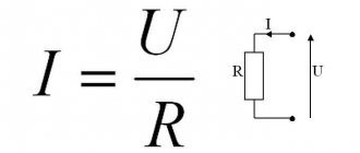
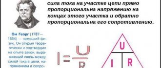
We have established through experiments that the current strength depends on two quantities: voltage (U) and resistance (R).
The higher the voltage, the greater the current. The higher the resistance, the lower the current.
When both voltage and resistance are doubled at the same time, the current does not change. If the voltage doubles and the resistance quadruples, the current eventually decreases by a factor of 2. Ultimately, we can conclude that the current strength is equal to the ratio (fraction) of voltage and resistance:
This law was discovered in the 19th century. physics teacher Georg Ohm
(1787 – 1854), for which it is called
Ohm’s law
. Method for calculating resistance from Ohm's law:
a short circuit is now clear
- with negligible resistance, the current increases sharply, which can easily cause a fire.
Sub Ohm - value below 1 Ohm. The lower the resistance -> the greater the power -> faster heating of the coil -> heating of the coil to higher temperatures -> more steam -> warmer steam -> due to the increase in temperatures of everything, it leads to increased heating of the vaping device.
Power is calculated using the formula: P = V*V / R (Voltage squared divided by resistance) Total, for example: R = 0.8 Ohm, V = 4.2V -> P = 22.05 W (W) R = 0.5 Ohm, V = 4.2 V -> P = 35.28 W (W) R = 0.2 Ohm, V = 4.2V -> P = 88.2 W (W)
As we said earlier, Ohm is a unit of measurement that expresses the resistance of a circuit to the flow of current. One Ohm of resistance will allow a current of 1 Ampere to flow through the circuit (through the consumer) when a voltage of 1 Volt is applied to it. Let's try to understand this with a more understandable example.
All power supplies are designed for maximum load (for a certain power).
Essentially, any energy source has a certain output voltage, as well as a certain permissible current. If the maximum current (power) is exceeded, the power supply may burn out.
Explanation in simple words
Electrical voltage U is the very reason that “forces” electric current I to flow. Electrical voltage always occurs when the charges are separated from each other, that is, all the negative charges are on one side, and all the positive charges are on the other. If you connect these two sides with an electrically conductive material, an electric current will flow.
The generally accepted definition of the term "electrical voltage".
Electrical voltage (or simply voltage) is the potential difference between two points in an electric field. It is the driving force for electric charge.
Potential in an electric field is the energy of a charged body, independent of its electric charge. For clarification, you can look at the comparison with the water circuit just below in the article.
There is another definition (from an 8th grade physics textbook):
Voltage is a physical quantity that characterizes an electric field. The electric voltage between two points of the electric field is numerically equal to the work done when a charge of 1 C is transferred between them by the forces of the electric field.
Comparison using a water flow model.
A good analogy to help you think about electrical voltage and potential is a water circuit. In this design, you have two pools at different heights that are connected by a pipe. In this pipe, water can flow from the upper pool to the lower one. The water is then pumped back to the upper basin using a pump as shown in the picture below.
Electrical Voltage - Comparison Using Water Flow Model
In your thinking, you can now easily compare a pump with a source of electrical voltage. In addition, the flow of water can be compared to electric current. The pump transports water from the lower pool to the upper one. From there it flows independently back to the lower pool. In this example, the pump is the flow driver. The greater the difference in height, the stronger the flow. The decisive factor is the potential energy of the upper basin. You can compare the difference in energy between the two pools with the difference in electrical potential. Simply put, a greater difference in height equals a greater electrical voltage.
Causes
In practice, both low and high voltage in the network have a number of negative consequences for household electrical appliances. Regardless of the level of the rated voltage in the network, an increase can occur for the following reasons:
- Artificial adjustment of the output level using an on-load tap-changer or tap-changer at a substation or package transformer substation. Due to frequent complaints about low voltage, the power supply organization increases the output parameter. As a result, in the last house connected to the line, the input voltage will correspond to the norm, and in the first it will significantly exceed.
- In addition, high voltage occurs during seasonal changes, the transition from day to night, changes in operating cycles of powerful equipment, etc. When the amount of electrical energy consumed differs significantly at the peak of the cycles. For example, in winter or before the start of centralized heating, household electrical networks suffer from numerous heating devices that cause low voltage. If at the same time the adjustment is made upward, then with warming a fairly large potential will arise on the transformer windings.
- Phase imbalance is caused by both damage to the network (for example, a break in the neutral wire) and a significant difference in the connected power to each line. At the same time, in some of the phases the alternating current increases and the voltage decreases, and in the neighboring phases, on the contrary, high voltage appears.
Rice. 1. phase imbalance - Emergency situation - due to damage in the networks, for example, a phase falling to zero, the potential difference will increase to a linear level. That is, instead of 220 V, 380 V will be supplied to household appliances. An identically high voltage can occur when the insulation breaks down between the high and low sides, when one of the phases breaks and zero-sequence currents occur.
Formula
The formula for electric voltage U, according to Ohm's law for a section of the circuit, has the form
U = R * I.
As can be seen from this formula, if the electrical voltage remains unchanged, then the greater the electrical resistance (R), the less the current (I).
Another formula for calculating electrical voltage is:
U = P/I.
That is, the electrical voltage U is equal to the power divided by the current I.
Unit of measurement of electrical voltage
The SI unit of measurement of electrical voltage is the Volt, abbreviated V (in honor of the Italian scientist A. Volta).
1 volt (1 V) is the voltage between two points of the electric field, when transferring a charge of 1 C between them, 1 J of work is done.
[U] = 1 V
Now you can explain the meaning of the inscription 4.5 V or 9 V on a round or coin battery. The point is that when transferring a charge of 1 C from one pole of the source to another (through the spiral of a light bulb or another conductor), the forces of an electric field can perform work of 4.5 J or 9 J, respectively.
In electrical engineering, voltage can vary from microvolts (1 µV = 1 * 10-6 V) and millivolts (1 mV = 10-3 V), to kilovolts (1 kV = 1 * 103 V) and megavolts (1 MV = 106 V)
You can convert individual units of measurement as follows:
1 V = 1000 mV, 1 mV = 1000 µV, 1 MV = 1000 kV, 1 kV = 1000 V.
Voltage loss
| Figure 3. Voltage loss along an electrical circuit |
Figure 3 shows an electrical circuit consisting of a battery, resistance r and long connecting wires that have their own specific resistance.
As can be seen from Figure 3, the voltmeter connected to the battery terminals shows 2 V. Already in the middle of the line, the voltmeter shows only 1.9 V, and near resistance r the voltage is only 1.8 V. This decrease in voltage along the circuit between individual points of this circuit is called voltage loss (drop).
Voltage loss along an electrical circuit occurs because part of the applied voltage is spent to overcome the resistance of the circuit. In this case, the voltage loss in a section of the circuit will be greater, the greater the current and the greater the resistance of this section of the circuit. From Ohm's law for a section of a circuit it follows that the voltage loss in volts in a section of the circuit is equal to the current in amperes flowing through this section multiplied by the resistance in ohms of the same section:
U = I × r.
Example 4. From a generator whose terminal voltage is 115 V, electrical energy is transmitted to an electric motor through wires whose resistance is 0.1 Ohm. Determine the voltage at the motor terminals if it consumes a current of 50 A.
Obviously, the voltage at the motor terminals will be less than at the generator terminals, since there will be a voltage loss in the line. Using the formula, we determine that the voltage loss is equal to:
U = I × r = 50 × 0.1 = 5 V.
If the voltage loss in the line is 5 V, then the voltage of the electric motor will be 115 - 5 = 110 V.
Example 5. A generator produces a voltage of 240 V. Electricity is transmitted through a line of two copper wires 350 m long, with a cross-section of 10 mm², to an electric motor consuming a current of 15 A. It is necessary to find out the voltage at the motor terminals.
The voltage at the engine terminals will be less than the generator voltage by the amount of voltage loss in the line. Line voltage loss U = I × r.
Since the resistance r of the wires is unknown, we determine it using the formula:
where ρ is the resistivity of copper (Table 1, in the article “Electrical resistance and conductivity”); the length l is 700 m, since the current has to go from the generator to the engine and from there back to the generator.
Substituting r into the formula, we get:
U = I × r = 15 × 1.22 = 18.3 V
Therefore, the voltage at the motor terminals will be 240 - 18.3 = 221.7 V
Example 6. Determine the cross-section of aluminum wires that must be used to supply electrical energy to a motor operating at a voltage of 120 V and a current of 20 A. Energy will be supplied to the engine from a 127 V generator along a line 150 m long.
We find the permissible voltage loss:
127 – 120 = 7 V.
The resistance of the line wires should be equal to:
From the formula
Let's determine the wire cross-section:
where ρ is the resistivity of aluminum (Table 1, in the article “Electrical resistance and conductivity”).
Using the reference book, select the available cross-section of 25 mm². If the same line is made with copper wire, then its cross-section will be equal to:
where ρ is the resistivity of copper (Table 1, in the article “Electrical resistance and conductivity”).
We choose a section of 16 mm².
Let us also note that sometimes it is necessary to deliberately achieve a voltage loss in order to reduce the magnitude of the applied voltage.
Example 7. For stable burning of an electric arc, a current of 10 A at a voltage of 40 V is required. Determine the amount of additional resistance that must be connected in series with the arc installation in order to power it from a network with a voltage of 120 V.
The voltage loss in the additional resistance will be:
120 – 40 = 80 V.
Knowing the voltage loss in the additional resistance and the current flowing through it, you can use Ohm’s law for a section of the circuit to determine the value of this resistance:
Electrical voltage in the circuit
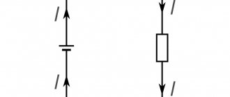
Voltage sources in circuits typically use one of the following symbols.
Voltage sources and electrical circuit
The voltage source always has two connections/poles. A plus pole and a minus pole. The voltage itself is indicated by a voltage arrow (UQ). For sources it is always displayed from plus to minus.
The electrical voltage dropped across a resistor can also be indicated by a voltage arrow (indicated in the diagram as a red arrow UR). This indicates the technical direction of the electric current.
You can also often hear the term “open circuit voltage” or “source voltage”. This is the output voltage of an unloaded source, i.e. source to which nothing is connected. If the circuit is closed with a load, then only the voltage at the source poles can be measured.
Electrical voltages for series and parallel connections
We already have an article on series and parallel connection of conductors in which we discuss this topic in more detail. So here we'll just cover some of the basics.
In a series connection, components are connected in a row.
Electrical voltage in series connection
Here the electrical voltage of the source is divided into resistors. This point is also described by Kirchhoff's second rule. The following applies here:
UQ = U1 + U2 + U3
that is, the source voltage is equal to the sum of the electrical voltages across the individual resistors. The source voltage is distributed differently across different resistors.
In an electrical circuit with a parallel connection, the components are arranged in parallel relative to each other. This can be seen in the following diagram.
Electrical voltage in a parallel circuit
Here it is much easier to determine the electrical voltages on the resistors, since with a parallel connection:
UQ = U1 = U2 = U3
Therefore, the electrical voltage across the resistors is as high as the electrical voltage of the source.
Typical frequently asked questions from readers
I connected the LIEBHERR {CUN3033} refrigerator via a PH-122 voltage relay. For about a week everything was fine, the network voltage was within the upper limit, the factory setting was 250 volts, and the refrigerator was working. But from December 31 to this day, the relay shows 250-253 volts and the refrigerator is turned off for approximately 5 hours a day. And at night I don’t even know how it works. Please tell me, is it possible to set the upper limit on the relay to 255 volts or is this unacceptable for a refrigerator? Could the relay be faulty? And why is there such high voltage in the network in an apartment in Moscow, or is this the norm? Please advise what to do? And also, the relay gets warm, a little, but the body is warm, is this normal or not?
As I understand it, you installed the RN-122 voltage control relay in the plug socket for connecting the refrigerator.
There are many questions, but let's consider everything in order. If we consider the permissible response limits, then, in accordance with the passport data, the regulation range for Umax is from 230 to 290 V. Therefore, yes, you can set the maximum voltage limit to more than 250 V. The fact that you have a maximum Umax limit of 250 V indicates about using factory settings (for voltage control relay RN-122, the response threshold for the minimum voltage is 185 V, and for the maximum voltage is 250 V). To change the value of the maximum response threshold, you need to perform the following steps (see the figure on the link):
Regarding the rated voltage, in accordance with GOST 32144-2013, the maximum limit is 253 V (that is, +10% to 230 V). But for many household appliances this is too much. I recommend that you double-check it with a multimeter or voltmeter; if this is indeed the case, contact the management company with an official statement. Otherwise, the relay may actually be faulty and simply needs to be replaced.
Electrical voltage measurement
Voltage measuring instruments, also called voltmeters, are always connected in parallel to the consumer on which the electrical voltage needs to be measured.
One of the most commonly used voltmeters is the digital multimeter (DMM), so we will show you the procedure for measuring voltage using a DMM. First you need to set the type of electrical voltage (DC - direct current or AC - alternating current).
For direct current it is necessary to pay attention to the correct polarity, i.e. connect the plus to the positive pole. The next step is to select the correct measuring range. If you can't estimate how big the quantity you're measuring is, set the range to the largest possible and work down from there until you find the right one. Finally, you only need to “read” the electrical voltage as an instrument.