Purpose and types
Three-phase transformer
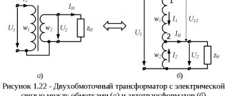
The classic station three-phase power transformer is used to convert high-voltage energy into a form convenient for the consumer. A high voltage (6.3-10 kilovolts) is supplied to its primary windings, and the output is 220 Volts, which are more convenient for everyday use. This value is measured between the phases and the neutral conductor of the transformer, called the neutral. It is usually designated as phase voltage, in contrast to linear 380 Volts, counted between each phase.
Three-phase step-down transformers of this class provide current transmission from the local substation through an underground cable or power line directly to the end consumer. For these purposes, a special 4-core cable in an armored core or an overhead wire of the SIP brand is used. Through them, electrical energy is delivered directly to its destination - to the input and distribution devices of the serviced territories and facilities.
According to their functional purpose, 3-phase transformers are divided into the following classes:
- linear (station) devices;
- special converting units.
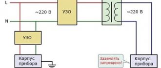
Particularly noteworthy are three-phase isolation transformers used for decoupling electrical circuits and power circuits.
Test transformer
Special devices are divided into the following types:
- Test transformers. These include three-phase autotransformer systems.
- Devices used to power special equipment: welding units, in particular.
- Balancing transformer units.
The first two types are used for research purposes. Three-phase balancing transformers are used to eliminate phase imbalance that occurs in electrical networks due to uneven load distribution.
In electrical engineering there are also variants of two-phase transformers, often used in electronic circuits and automation devices. They are designed so that the two output voltages are shifted relative to each other by 90 electrical degrees. Most often, such electrical solutions are used in welding equipment.
Purpose
In the modern electrical network, consumers have often begun to be used that require not the classic 380 V, but specialized 220 V. There are quite a lot of areas for its application.
These include everyday life, as well as the service and communal services. In those cases when it is necessary to convert its large industrial value 380, they turn to a step-down transformer. With its help, the necessary voltage is created with one or more phases to power the target consumers. There are quite a lot of devices that need to interact with such a module:
- Home appliances
- Working power tool
- Maintenance equipment for residential and commercial properties
- Lighting modules for construction sites
- Industrial machines and equipment
Let's figure out what voltage values these transformer devices convert into.
If you plan to use the transformer as a step-down and connect its output windings as a star, then the output linear voltage will be 220, and the phase voltage (between N and L1) will be 127 volts. This option is used when we need to connect an unsymmetrical load.
If we connect it with a triangle, then the linear voltage will be equal to the phase voltage, that is, 220, while the linear current will be √3 times greater than the phase current. This winding connection is used to power symmetrical loads such as motors.
It is important to follow safety standards when working with electrical voltage. Separating devices are designed for these purposes. Their fundamental difference lies in the presence of special elements on the circuit diagram. Special components make important protection and regulation functionality available.
Transformer device
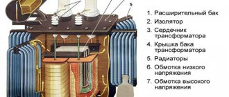
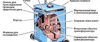
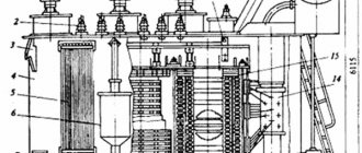
Design of a three-phase power transformer
According to their design, three-phase transformers represent a prefabricated structure consisting of the following components:
- base, made in the form of a durable plastic frame;
- magnetic circuits placed in frame sections;
- a set of primary and secondary coils with wire windings;
- distribution (soldering) panel with contact blocks;
- cooling system necessary to remove heat from the work area.
Each of the known versions of such devices in one form or another contains all the designated nodes.
However, they differ in the way the windings are connected, as well as the type of magnetic circuit used in them. The design features of individual models are reflected in their performance characteristics, in particular the magnitude of losses in the magnetic circuit and efficiency. The exception is the panel for wiring taps of transformer windings, thanks to which it is possible to combine groups of connections to obtain the desired configuration.
Three-phase transformers of the TS, TSZ series
Buy three-phase transformers of the TS, TSZ series
Three-phase transformers series TS, TSZ voltage class 0.66 kV
Three-phase dry transformers of voltage class 0.66 kV are intended for use in general-purpose electrical installations and in moderately cold climates. Temperature range from -5 to + 40 C, relative air humidity no more than 80%, altitude above sea level no more than 1000 m. The environment must be non-explosive, not contain aggressive gases, vapors and conductive dust in concentrations that destroy materials and reduce parameters products to unacceptable limits. Insulation heat resistance class – B. Rated frequency – 50 Hz.
Symbols of a dry transformer:
TS(1) – (2)/380/(3) UHL4, D/Un-11 (U/Un-0) T- three-phase C- dry (1)- if there is a “Z” with a casing, without a letter there is no casing . (2) - rated power, kVA 380 - rated voltage of the high voltage winding (HV), V. (3) - voltage of the low voltage winding (LV), V. UHL-4 - climatic version and placement category
Connection diagram and winding connection group:
D - triangle winding connection diagram, U - star winding connection diagram, n - presence of an insulated neutral, 0, 11 – winding connection group.
Design:
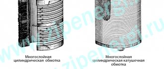
The transformer consists of the following components: magnetic core, windings, taps, casing, terminal panels. The magnetic core of the rod-type transformer is made of cold-rolled electrical steel 0.35 mm thick with an insulating coating without through pins. The windings are multilayer, cylindrical with axial ventilation channels, the winding wire is aluminum or copper, depending on the order. The windings on the rods are secured with vertical tie rods and yoke beams through gaskets made of insulating material. The transformer casing (if any) is frameless, hinged. All metal parts of the transformer have protective anti-corrosion coatings.
The main parameters of dry transformers TS, TSZ are indicated in the table
:
| Transformer type | IP degree of protection | Rated power, kVA | Rated voltage, V | Winding connection diagram and group | Losses, kW | Short circuit voltage, % | Dimensions, mm | Weight, kg | ||||
| HV winding | LV winding | x.x. | short circuit | L | B | H | ||||||
| TS-6.3/0.66-UHL-4 | IP-00 | 6,3 | 380 | To order | U/Un-0; D/Un-11 | 0,04 | 0,15 | 3,8 | 460 | 200 | 370 | 75 |
| TSZ-6.3/0.66-UHL-4 | IP-21 | 6,3 | 380 | To order | U/Un-0; D/Un-11 | 0,04 | 0,15 | 3,8 | 490 | 250 | 400 | 83 |
| TS-10/0.66-UHL-4 | IP-00 | 10 | 380 | To order | U/Un-0; D/Un-11 | 0,07 | 0,27 | 3,8 | 540 | 410 | 665 | 130 |
| TSZ-10/0.66-UHL-4 | IP-21 | 10 | 380 | To order | U/Un-0; D/Un-11 | 0,07 | 0,27 | 3,8 | 605 | 410 | 665 | 150 |
| TS-16/0.66-UHL-4 | IP-00 | 16 | 380 | To order | U/Un-0; D/Un-11 | 0,11 | 0,42 | 3,8 | 650 | 450 | 665 | 160 |
| TSZ-16/0.66-UHL-4 | IP-21 | 16 | 380 | To order | U/Un-0; D/Un-11 | 0,11 | 0,42 | 3,8 | 730 | 450 | 665 | 180 |
| TS-25/0.66-UHL-4 | IP-00 | 25 | 380 | To order | U/Un-0; D/Un-11 | 0,15 | 0,64 | 3,8 | 800 | 500 | 725 | 215 |
| TSZ-25/0.66-UHL-4 | IP-21 | 25 | 380 | To order | U/Un-0; D/Un-11 | 0,15 | 0,64 | 3,8 | 880 | 500 | 725 | 230 |
| TS-40/0.66-UHL-4 | IP-00 | 40 | 380 | To order | U/Un-0; D/Un-11 | 0,22 | 0,88 | 3,8 | 820 | 450 | 780 | 280 |
| TSZ-40/0.66-UHL-4 | IP-21 | 40 | 380 | To order | U/Un-0; D/Un-11 | 0,22 | 0,88 | 3,8 | 865 | 450 | 780 | 300 |
| TS-63/0.66-UHL-4 | IP-00 | 63 | 380 | To order | U/Un-0; D/Un-11 | 0,30 | 1,30 | 3,8 | 900 | 500 | 950 | 400 |
| TSZ-63/0.66-UHL-4 | IP-21 | 63 | 380 | To order | U/Un-0; D/Un-11 | 0,30 | 1,30 | 3,8 | 1000 | 500 | 950 | 425 |
| TS-100/0.66-UHL-4 | IP-00 | 100 | 380 | To order | U/Un-0; D/Un-11 | 0,40 | 1,45 | 3,8 | 980 | 550 | 985 | 520 |
| TSZ-100/0.66-UHL4 | IP-21 | 100 | 380 | To order | U/Un-0; D/Un-11 | 0,40 | 1,45 | 3,8 | 1030 | 550 | 985 | 550 |
| TS-160/0.66-UHL-4 | IP-00 | 160 | 380 | To order | U/Un-0; D/Un-11 | 0,50 | 1,95 | 3,8 | 1150 | 610 | 960 | 700 |
| TSZ-160/0.66-UHL4 | IP-21 | 160 | 380 | To order | U/Un-0; D/Un-11 | 0,50 | 1,95 | 3,8 | 1210 | 610 | 960 | 750 |
Manufacturer:
Dry power transformers TS and TSZ are manufactured by Elektroproekt LLC to order. Upon customer request, it is possible to manufacture transformers with any combination of voltages up to 660 V, with other circuits and groups of connections.
Phone ext. 209
Information applies to the following catalog titles
Winding connection methods
Connection diagrams for windings of three-phase transformers
The main difference between various transformer diagrams is the configurations used when they are turned on (methods of connecting the windings). When organizing centralized energy supply, two classical schemes are traditionally used, called “triangle” and “star”. The first option involves sequential connection of the primary and secondary phase windings: the end of one coil is connected to the beginning of the next).
When using a star circuit, the beginnings of all the phase conductors of the primary and secondary windings are combined at one point, called the neutral, and their ends are connected to a 3-wire load line. In this case, a cable containing four cores will be required to transmit electricity. When connecting secondary transformer windings connected in a “triangle” to the line, only three cores are used. Another option for their inclusion is possible, which is called “interconnected star”. However, due to the rarity of its use, it is not considered.
Configuration options
Winding options
When organizing power supply systems, several combinations of connecting the primary and secondary windings of a three-phase transformer are possible. The set of switching actions performed in this case:
- The primary winding is made as a “star”, and the secondary winding is made as a “triangle”.
- The second approach uses the reverse order of inclusion.
- In the third case, the already discussed combination of the “star”-“star” type or the option with two triangles (another name is delta-delta) is used.
To take into account all methods of connecting primary and secondary windings and subsequent calculation of transformer parameters in electrical engineering, special identification tables are used. They provide possible combinations and combinations used if you want to connect a transformer to a line and get the most out of it. The efficiency of the entire energy supply system depends on the correct choice of this combination in each specific case.
Parallel connection
Connecting secondary windings
Parallel connection of identical secondary windings allows you to increase the power (current) at the output of the device. This way it is possible to increase the efficiency and load capacity of the serviced line.
When using this approach, you will need to take into account one important detail related to the order of connection of the secondary windings. To obtain the expected results, the windings must be turned on in phase, which means connecting the same type of ends of all three coils at one point. If this rule is violated, the voltage at the output of two windings connected out of phase will be close to zero (the substitution principle applies). When this error is made when turning on a transformer, its power and efficiency are significantly reduced. If, during a secondary check, it is discovered that the voltage has not changed compared to a single connection, then the coils are connected in phase.
A converter device, defined as a 220 to 380 Volt 3 phase transformer, can be obtained if a special circuit is used to increase the output voltage. Its peculiarity is the presence of one primary and three secondary windings connected in a star or delta circuit.
Photos of step-down transformers
Read here! Why the RCD trips - the main reasons, methods for finding and eliminating the problem. Checking the device yourself