Nowadays, electrical wiring is carried out using wires with different insulation colors. And the point here is not about some fashion trends or the beauty of the product itself, but about the safety and ease of use of this electrical wiring.
After all, colored insulation can perform two functions simultaneously - protection against electric shock or protection against short circuits by applying insulating material to the conductor, and with the help of the color of this very insulating material, it helps the electrician determine the purpose of this conductor.
To avoid confusion, all color colors were reduced to a single standard, described in the PUE.
Color marking can be done both along the entire length of the conductor and at the connection points of the conductors or at their ends. To do this, colored electrical tape or heat-shrinkable tubes (cambrics) can be used.
In this article we will look at color marking in single-phase and three-phase circuits, as well as in DC circuits.
Wire colors in a single-phase network
Different colors of wire insulation become most relevant when the installation of electrical wiring is carried out by one person, and repairs and maintenance are carried out by another. The main purpose of color marking is to make it easy and quick to determine the purpose of any of the wires.
Phase wire colors
According to the PUE, phase wires in a single-phase electrical network can have the following insulation color - black, red, brown, gray, purple, pink, orange, white, turquoise. This color marking is quite convenient - when you see a wire with this color of insulation, it becomes clear that you have a phase in front of you (but it is still better to double-check, since in practice there are cases when the marking is not observed).
Zero working conductor or neutral
The neutral or neutral working conductor (N) is usually made with a wire with blue insulation.
Neutral protective conductor and neutral combined conductor
The neutral protective conductor (PE) has a yellow-green insulation color. The combined neutral and working conductor (PEN) has a blue color with yellow-green marks at the end, or vice versa - a yellow-green color with blue marks at the end.
If you do not have a wire of a suitable color, then installation can be done with a wire of any color (except for the protective PE conductor that is colored) by marking the ends of this wire with colored electrical tape or heat-shrink tubing, which have a color indicating the purpose of the conductor. You can also mark the ends of the conductor with the desired color in the case when the installation has already been carried out with a conductor of a different color.
Below are the colors that indicate phase, neutral, protective and combined conductors:
Types of material for manufacturing
Made from aluminum, copper and a mixture of aluminum and steel. The former are characterized by high electrical conductivity, corrosion resistance, low weight and low cost. Busbars made of aluminum and steel are particularly durable, elastic and ductile, but have low electrical conductivity. Copper has high resistivity and excellent thermal and electrical conductivity.
Aluminum as the main material for manufacturing
Colors of wires and buses in the AC network for a three-phase connection
To maintain the correct phase rotation when connecting three-phase consumers of electrical energy, color marking of buses and cables is also used. This makes life much easier for installers and repairmen, since by the color of the cable or bus, you can determine the phase that is connected or will be connected to this cable or bus. Unlike single-phase consumers, where the phase wire can be made of cables with different insulation colors (list above), for three-phase consumers the colors that can be used to indicate phases are strictly regulated by the PUE.
For a three-phase connection, phase A should be indicated in yellow, phase B in green, phase C in red. Zero working, protective and combined conductors have the same color as with a single-phase connection.
It is permissible to color code cables and buses not along their entire length, but only at the points where cables or buses are connected, as shown in the figure above.
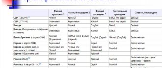
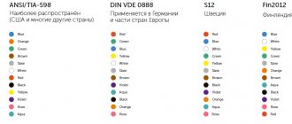
Also, color codes may comply with the international standard IEC 60446 or may use the coding adopted within the country by the relevant regulatory documents. For example, in the USA and Canada, different color codes are used for grounded and ungrounded systems. Below is a table showing the color coding of cables and busbars in different countries for comparison:
Tire color code
Color designation in electrical installations of buses, wires, conductors
Color designation of tires
[PUE / Ministry of Energy of the USSR. - 6th ed. reworked and additional]
According to the sixth edition of the PUE, electrical installations must be able to easily recognize parts related to their individual elements (simplicity and clarity of diagrams, proper arrangement of electrical equipment, inscriptions, markings, colors).
The alphanumeric and color designations of tires of the same name in each electrical installation must be the same.
Tires must be marked:
- 1) with alternating three-phase current:
- phase A buses - yellow,
- phase B - green,
- phase C - red,
- zero working N - blue,
- the same tire, used as a zero safety tire, with longitudinal stripes of yellow and green colors;
- 2) with alternating single-phase current:
- bus A, connected to the beginning of the power source winding, is yellow,
- B, attached to the end of the winding, is in red.
- 3) at constant current:
- positive bus [+] - red,
- negative [–] – blue,
- zero working M - blue;
- 4) reserve as a redundant main bus; if the reserve tire can replace any of the main tires, then it is indicated by transverse stripes in the color of the main tires.
Single-phase current buses , if they are a branch from the buses of a three-phase system, are designated as the corresponding three-phase current buses.
The color coding must be carried out along the entire length of the tires if it is also provided for more intensive cooling or for anti-corrosion protection.
It is allowed to carry out a color designation not along the entire length of the busbars, only a color or only an alphanumeric designation, or a color in combination with an alphanumeric designation only at the points where the busbars are connected; if non-insulated busbars are not available for inspection during the period when they are energized, then it is permissible not to mark them. At the same time, the level of safety and visibility when servicing the electrical installation should not be reduced.
Wiring designation
[PUE-7]
According to the seventh edition of the PUE (2002, Ministry of Energy of the Russian Federation), electrical wiring must provide the ability to be easily recognized along the entire length of the conductors by color:
- blue color - to indicate the zero working or middle conductor of the electrical network;
- two-color combination of green and yellow - to indicate the protective or neutral protective conductor;
- a two-color combination of green and yellow along the entire length with blue marks at the ends of the line, which are applied during installation - to indicate the combined neutral working and neutral protective conductor;
- black, brown, red, purple, gray, pink, white, orange, turquoise - to indicate the phase conductor.
Color designation according to functional purpose
[GOST 12.2.007.0]
Color identification of conductors according to the functional purpose of the circuits in which they are used (according to GOST 12.2.007.0):
- for conductors in power circuits - black;
- for conductors in control, measurement and signaling circuits of alternating current - red;
- for conductors in DC control, measurement and signaling circuits - blue;
- for neutral protective conductors - a combination of green and yellow;
- for conductors connected to the neutral working conductor and not intended for grounding - blue.
Wire Identification
[GOST IEC 60204-1-2002]
According to GOST IEC 60204-1-2002 “ELECTRICAL EQUIPMENT OF MACHINES AND MECHANISMS”, if color marking is used to identify wires, the following colors can be used: black, brown, red, orange, yellow, green, blue (including light blue), violet, grey, white, pink, turquoise.
Note: The list of colors is taken from IEC 60757.
For safety reasons, the colors green and yellow should not be used if they could be confused with the green-yellow two-color combination.
The protective conductor must be easily recognizable due to its shape, location, marking or color. When color designation is used, it should be a two-color combination of green and yellow. It is used along the entire length of the wire. This combination is intended for protective conductor only.
On insulated wires, the two-color combination of green and yellow should be such that over a length of 15 mm one of the colors covers at least 30%, but not more than 70% of the surface of the wire, and the other color covers the remaining part.
When protective conductor is easily identifiable due to its shape, design, location (e.g., braided conductor), or when insulated conductor is not easily accessible, color coding along its entire length is not necessary. However, the ends or accessible parts shall be clearly marked with the graphic symbol 417-IEC-5019 [1] or a two-color combination of green and yellow.
When the circuit includes a neutral conductor, indicated by color, the latter shall be light blue (IEC 60446, 3.1.2). Where possible, light blue should not be used to indicate other wires.
In the absence of a neutral wire, the light blue wire can be used for other purposes, but not as a protective wire.
When color designation is used, bare wires used as neutral wires should be marked with a light blue stripe 15 to 100 mm wide, a color that is duplicated on each sheath, equipment or in each accessible location, or painted light blue along the entire length .
Identification of other wires should be carried out using color (either as a whole, or in one or more stripes), numbers, letters, or a combination of these. The numbers must be Arabic, the letters must be Latin (uppercase or lowercase).
Insulated unipolar rigid wires must have the following color designation:
- black - AC and DC power circuits;
- red - AC control circuits;
- blue - DC control circuits;
- orange - interlock control circuits powered by an external energy source.
Exceptions to the above are permitted:
- for internal cables on independent devices, purchased separately with a complete set of cables;
- when the insulating material used cannot be painted in the required colors;
- when multi-wire cable is used, except for the green-yellow two-color combination.
| [1] Graphic symbol 417-IEC-5019 |
Colors of wires and buses in DC circuits
DC circuits typically use only two buses, namely plus and minus. But sometimes DC circuits have a middle conductor. According to the PUE, buses and wires are subject to the following markings in DC circuits: positive bus (+) - red, negative (-) - blue, zero operating M (if available) - blue.
Classification by section shape
The busbar duct is classified, in addition to the topic of how busbars are designated for direct current, according to the material of manufacture, design, insulation and geometric shape of the section. The result is copper, aluminum, steel-aluminum, flexible, rigid, insulated or non-insulated, as well as rectangular, two-way and three-way, box and tubular.
It has flexibility and a high degree of tension. Equipped with a vibration damper and a flexible jumper responsible for temperature tension.
Conductors with a flat rectangular cross-section have good heat conductivity. Their disadvantage is that they are difficult to assemble and have an unevenly distributed current.
Note! Box-section devices are used where there is a mains voltage of 10 kilovolts. Used in turbogenerators.
The tubular cross-sectional shape is the most effective. It has good thermal conductivity and durability. Capable of evenly distributing the electric field and preventing the appearance of corona.
Flat variety for solid chain
Changes in color marking of buses and wires
In the Russian Federation, GOST R 50462-92, which regulated the identification of conductors in electrical networks using digital and color designations from 01/01/2011, was replaced by GOST R 50462-2009, which has quite significant differences from GOST R 50462-92 and has some contradictions with PUE 7. Below is a table containing recommendations for color marking of busbars and cables in accordance with GOST R 50462-92:
What it is
This is the connecting element of a power system or installation that allows the creation of one equivalent point. Defined according to GOST of 2007 as a connecting conductor having low resistance. The combination of such components is a busbar. It is mounted on insulating supports and placed in the electrical system channel. It must have the main quality - high resistance to electric shocks with thermal and dynamic overloads.
Definition from the textbook
Why is labeling necessary?
Specific colors in electrics were not chosen by chance. Colored wiring is necessary for safe electrical work to avoid short circuits and electric shock. Previously, the color of conductors was black or white, which resulted in great inconvenience for electricians.
Previously, when disconnecting, it was necessary to supply power to the conductors, after which zero and phase were determined using control. Using coloring took all that pain away because everything became very clear.
Color coding is almost always applied along the entire length of the conductor. It helps to establish the assignment of each conductor to a specific group in order to facilitate their switching. There are three types of wires in electrics: phase, neutral and ground.
electrical safety
Alternating electric current with a voltage of 220 V or 380 V is dangerous for humans. Careless touching of exposed wires or metal parts of electrical equipment that may be live can result in severe burns or fatal injury. For this purpose, the PUE gives an answer to the questions: how the color of the wires phase and zero, L and N in electrics will help to clearly determine the security system used in a given electrical network.
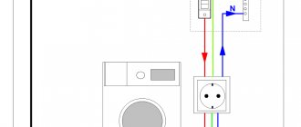
Rules for observing the colors of electrical wiring during installation
A three-core or two-core wire is laid from the distribution box to the switch, depending on what type of switch is installed: a single-key or two-key switch. The phase is broken, not the neutral conductor. If there is a white conductor available, it will be the power supply. The main thing is to maintain consistency and consistency in coloring with other electricians, so that it doesn’t turn out like in Krylov’s fable: “The Swan, the Crayfish and the Pike.”
On sockets, the protective conductor (yellow-green) is most often clamped in the middle part of the device. We maintain polarity, zero worker is on the left, phase is on the right.
But there are surprises from manufacturers, for example, one conductor is yellow-green, while the other two may turn out to be black.
Perhaps the manufacturer decided, if there was a shortage of one color, to use what was available. Don't stop production! Failures and errors happen everywhere. If you come across exactly the same one, it’s up to you to decide where the phase is and where the zero is, you just need to run around with the control.