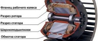
Classification by section shape
The busbar duct is classified, in addition to the topic of how busbars are designated for direct current, according to the material of manufacture, design, insulation and geometric shape of the section. The result is copper, aluminum, steel-aluminum, flexible, rigid, insulated or non-insulated, as well as rectangular, two-way and three-way, box and tubular.
It has flexibility and a high degree of tension. Equipped with a vibration damper and a flexible jumper responsible for temperature tension.
Conductors with a flat rectangular cross-section have good heat conductivity. Their disadvantage is that they are difficult to assemble and have an unevenly distributed current.
Note! Box-section devices are used where there is a mains voltage of 10 kilovolts. Used in turbogenerators.
The tubular cross-sectional shape is the most effective. It has good thermal conductivity and durability. Capable of evenly distributing the electric field and preventing the appearance of corona.
Flat variety for solid chain
How are zero working (neutral) conductors designated?
| Indicated by the letter N and green | Incorrect answer |
| Indicated by the letter N and white | Incorrect answer |
| Indicated by the letter N and blue color | Correct answer |
| Indicated by the letter N and the color yellow | Incorrect answer |
Who are the operational personnel?
| Personnel performing operational management and maintenance of electrical installations (inspection, operational switching, preparation of the workplace, admission and supervision of workers, performance of work in the order of routine operation) | Correct answer |
| Repair personnel specially trained and prepared for operational maintenance of the electrical installations assigned to them within the approved scope | Incorrect answer |
| Personnel providing maintenance and repair, installation, adjustment and testing of electrical equipment | Incorrect answer |
| Personnel entrusted with the responsibility for organizing technical and operational maintenance, carrying out repair, installation and commissioning work in electrical installations | Incorrect answer |
In what case is the certificate for testing knowledge of norms and rules of work in electrical installations subject to replacement?
| Upon expiration of the electrical safety group | Incorrect answer |
| In case of loss of ID | Incorrect answer |
| When increasing the electrical safety group | Incorrect answer |
| In case of change of position | Correct answer |
For how long can a work order for work on electrical installations be extended?
| No more than 5 calendar days from the date of renewal | Incorrect answer |
| No more than 10 calendar days from the date of renewal | Incorrect answer |
| No more than 15 calendar days from the date of extension | Correct answer |
| No more than 20 calendar days from the date of renewal | Incorrect answer |
Who in the organization monitors the operation of electricity meters?
| Operations staff | Correct answer |
| Administrative and technical staff | Incorrect answer |
| Electrical staff | Incorrect answer |
| Electrotechnological personnel | Incorrect answer |
How is electricity metered during the repair of measuring instruments while the process equipment is running?
| Based on average data obtained over the last three months | Incorrect answer |
| During repairs, backup measuring instruments must be installed | Correct answer |
| No measurements are taken during this period. | Incorrect answer |
Which of the following grounding systems belongs to the TN ?
| A system in which the neutral of the power supply is isolated from earth or is grounded through high-resistance instruments or devices, and the exposed conductive parts of the electrical installation are grounded | Incorrect answer |
| A system in which the neutral of the power source is solidly grounded, and the exposed conductive parts of the electrical installation are grounded using a grounding device electrically independent of the solidly grounded neutral of the source | Incorrect answer |
| A system in which the neutral of the power source is solidly grounded, and the open conductive parts of the electrical installation are connected to the solidly grounded neutral of the source via neutral protective conductors | Correct answer |
What protection means are considered additional insulating electrical protective equipment for electrical installations with voltages up to 1000 V?
| Dielectric galoshes, dielectric carpets and insulating stands, insulating caps, coverings and linings, ladders, insulating fiberglass stepladders, rods for transfer and potential equalization | Incorrect answer |
| Dielectric galoshes, dielectric carpets and insulating supports, insulating caps, coverings and linings, ladders, insulating fiberglass stepladders | Correct answer |
| Dielectric galoshes, dielectric carpets and insulating supports, insulating caps, coverings and linings, ladders, insulating rods of all types | Incorrect answer |
| Dielectric galoshes, dielectric carpets and insulating stands, insulating caps, coverings and linings, ladders, insulating fiberglass stepladders, voltage indicators | Incorrect answer |
What is the frequency of inspection of the condition of protective equipment used in electrical installations?
| At least once a month | Incorrect answer |
| At least once every three months | Incorrect answer |
| At least once every six months | Correct answer |
| At least once a year | Incorrect answer |
TICKET 2
Who is covered by the Interindustry Rules on Labor Protection (Safety Rules) when operating electrical installations?
| For employees of industrial enterprises that include electrical installations | Incorrect answer |
| For employees of organizations, regardless of ownership and organizational and legal forms, and other individuals engaged in the maintenance of electrical installations, carrying out operational switching in them, organizing and performing construction, installation, adjustment, repair work, testing and measurements | Correct answer |
| For employees of organizations engaged in the maintenance of electrical installations | Incorrect answer |
| For employees of all organizations, regardless of their form of ownership, engaged in maintenance and performing construction, installation and repair work in them | Incorrect answer |
What are employees who directly service electrical installations personally responsible for?
| For untimely and unsatisfactory maintenance of electrical installations | Incorrect answer |
| For violations that occurred through their fault, as well as for their improper elimination of violations in the operation of electrical installations in the serviced area | Correct answer |
| For failure to comply with job description requirements | Incorrect answer |
| For violations in the operation of electrical equipment | Incorrect answer |
Which electrical safety group should the person responsible for electrical equipment in electrical installations with voltages up to 1000 V have?
| Second | Incorrect answer |
| Third | Incorrect answer |
| Fourth | Correct answer |
| Fifth | Incorrect answer |
Which electrical safety group should the chairman of the commission for testing the knowledge of electrical personnel of the Consumer with electrical installations above 1000 V have?
| Third | Incorrect answer |
| Fourth | Incorrect answer |
| Fifth | Correct answer |
| Either fourth or fifth | Incorrect answer |
When is a responsible work manager usually appointed?
| In electrical installations with voltages up to 1000 V | Incorrect answer |
| In electrical installations with voltages over 1000 V | Correct answer |
| In all electrical installations | Incorrect answer |
| In electrical installations with voltages above 10 kV | Incorrect answer |
What document is used for testing electrical equipment using a mobile testing unit?
| By order | Incorrect answer |
| Alongside | Correct answer |
| By order | Incorrect answer |
| According to the work plan | Incorrect answer |
What should be the verification period for a current transformer built into power equipment?
| Calibration interval of the equipment on which they are installed | Incorrect answer |
| Overhaul interval of the equipment on which they are installed | Correct answer |
| Estimated service life of the equipment | Incorrect answer |
| The verification period does not depend on the equipment on which the current transformer is installed | Incorrect answer |
Letter marking
The letter marking is designed to allow the user to correctly read the diagram, know exactly how the busbars are designated for three-phase alternating current, and determine the type of busbar trunking. Like colors, letters have their own meaning and have a corresponding winding pattern. All existing letters with the meaning of zero and positive branches of the source network are indicated in the figure below.
Note! It is important to note that they are mandatory and regulated at the legislative level.
Letter marking
In general, busbars are a necessary element of any electrical installation, which allows you to reduce the installation area with material consumption and labor costs. They are needed where low active and reactance is required. There is a classification based on material of manufacture, design, insulation and geometric shape of the section. Busbars with single-phase alternating current are indicated in yellow. They are also marked with letters.
Designation
It is necessary to ensure that users of electrical appliances are protected from electric shock. In addition, it is required in order to calculate the value. In response to the question of how the neutral protective conductor is designated, it is worth pointing out that there is a letter and color designation for protective grounding conductors.
Literal
The letter designates a PE type conductor device. Neutral electrical element - N.
You might be interested in: Features of a voltage divider
Note ! Combined types are designated as PEN, if you need to know how zero working neutral conductors are designated.
Literal value
Color
Conducting elements, according to GOST from 2009, are designated blue with yellow-green stripes at the ends.
Color value
A protective conductor is an element that is needed to prevent electrical shock to people or animals. A neutral device is one that has a voltage of up to 1 kilowatt. The designation can be represented by the letter N or a combination of the letters PE and PEN. As for the tone, it is indicated in blue.
Source
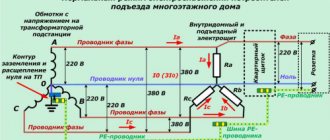
What is the danger of damaging the neutral wire?
Overheating of neutral wires due to poor contact
Zero is damaged due to mechanical stress, short circuits, poor-quality connections or as a result of old wiring. Neutral break:
- PEN conductor in the power cable - there is only one ground loop left, which is not visually noticeable;
- combustion of a conductor in the switchboard - phase conductors become distorted, the voltage increases to 380 V;
- there is a break in the apartment panel - the second phase remains in the sockets, household appliances are not powered from them.
Damage to the neutral prevents the potential equality of networks with different loads, as a result of which household appliances can burn out. In such cases, isolation breaks through. In old housing stock with a TN-C connection diagram (zero - protective conductor), if there is a breakdown, there is a risk of electric shock. In new buildings, damage to the zero leads to the fact that when touching the equipment, light discharges of current are felt.
Current discharges from touching the equipment body also indicate its malfunction.
Purpose of conductors
The use of neutral conductors in an electrical panel The neutral working conductor has another name - network conductor.
The load current flows through it. In the diagram it is designated by the Latin letter “N”. The main task of the neutral protective conductor is to ensure safety. In systems with a zero terminal of a solidly grounded transformer, it switches the conductive parts of electrical receivers and the zero point of the supply transformer. In emergency or emergency situations, they are under attack.
The following electrical elements are subject to protection from indirect contact (according to PUE 1.7.76):
System with PEN wire and two zeros
As protection, switching of these devices with a solidly grounded neutral in TN or TT, IT systems is used. The last two are grounded.
Schematically, the neutral protective conductor is designated “PE”. When the electrical circuit is operating normally, no current flows through the PE.
In the diagrams, the combination “PE” means the neutral protective conductor, as well as all protective segments of the circuit, for example, laid buses and conductors, grounding conductors, individual conductors in cables, as well as a wire in the potential equalization system.
Neutral connection rules
Chapter 1.7 PUE examines in detail electrical safety when grounding. The Electrician's Bible says:
- for electrical installations with voltages over 1 kV, a solidly grounded neutral is required, which discharges large fault currents into the ground;
- for equipment up to 1 V, an isolated or solid neutral can be used;
- the solidly grounded neutral must be grounded and connected to the grounding line through a transformer;
- grounding and neutral are carried out using copper (cross-section 4 mm2), aluminum (cross-section 6 mm2), insulated (1.5 mm2 and 2.5 mm2) cables;
- copper cables connected in one twist must have a cross-section of 1 mm2, aluminum cables - 2.5 mm2;
- if 3 wires are pulled from the panel of an apartment or floor, a protective neutral is used;
- if the group network is carried out using two cables, the protection neutral is extended from the nearest switchboard;
- All household appliances are added to zero - kettle, air conditioner, computer, washing machine, boiler, refrigerator.
Provided the connection diagram is correct, the protective neutral wire can prevent destruction of the electrical network and injury in cases of short circuit. The neutral evenly distributes the load across all lines, floors and apartments of a high-rise building. When connecting it for the first time and reconnecting it, you should be guided by the PUE.
Colors of wires and buses in the AC network for a three-phase connection
To maintain the correct phase rotation when connecting three-phase consumers of electrical energy, color marking of buses and cables is also used. This makes life much easier for installers and repairmen, since by the color of the cable or bus, you can determine the phase that is connected or will be connected to this cable or bus. Unlike single-phase consumers, where the phase wire can be made of cables with different insulation colors (list above), for three-phase consumers the colors that can be used to indicate phases are strictly regulated by the PUE.
For a three-phase connection, phase A should be indicated in yellow, phase B in green, phase C in red. Zero working, protective and combined conductors have the same color as with a single-phase connection.
It is permissible to color code cables and buses not along their entire length, but only at the points where cables or buses are connected, as shown in the figure above.
Also, color codes may comply with the international standard IEC 60446 or may use the coding adopted within the country by the relevant regulatory documents. For example, in the USA and Canada, different color codes are used for grounded and ungrounded systems. Below is a table showing the color coding of cables and busbars in different countries for comparison:
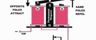
Principle of operation
TN-S
In new buildings and old buildings, the energy transmission scheme is fundamentally different. The electrical network of new buildings is designed according to the TN-S principle:
- electricity comes from transformers with a secondary winding connected in a star connection (wires converging at the zero point);
- the second part of the ends of the cables is led to terminals A, B, C, also connected at the zero point, and is connected via a ground loop to the substation;
- a high-voltage wire with zero resistance is divided into protective PE (yellow-green) and working N (blue).
In the general switchboard of a new building, 3 phases, a protective conductor and a neutral wire are supplied.
Old buildings do not have protective wiring. The outdated four-wire TN-C system is implemented there:
- the neutral grounded conductor is located in the distribution box;
- phase and neutral from the transformer are connected to the building through underground or above-ground high-voltage cables;
- the wires are connected in the input panel, forming a three-phase system with an operating voltage of 220 or 380 V;
- From the panel, wiring is carried out to apartments and entrances;
- consumers receive electricity from the wires of one of the phases through a network with a voltage of 220 V;
- the difference in load is eliminated by connecting the neutral N-wire.
Electrical wiring diagrams for older homes are outdated and unsafe.
Operating modes
There are the following neutral modes of electrical networks:
- solidly grounded (networks at 380 volts - 110 kilovolts) - the neutral and ground potentials are the same;
- isolated (networks at 6, 10 and 35 kilovolts) – minor current leaks are observed between the neutral and ground;
- part of an electrical network with low resistance impedance and ground resistance.
A neutral wire is used to prevent emergency voltage surges in a phase, for the purpose of relay protection against phase-to-ground faults, as well as to ensure the reliable operation of electrical appliances.
1.TN-C grounding system
TN-C system is a TN system in which the neutral protective and neutral working conductors are combined in one conductor along the entire length of the line from the source to the apartment.
Apartment power supply system TN-C
Important! This power supply system is used in all old houses. Since 2007, according to the PUE (Electrical Installation Rules), the TN-C wiring diagram in newly built houses is prohibited.
In case of major renovation of an apartment, it is necessary to convert the apartment's TN wiring diagram to the TN-CS system (see below).
Now about grounding, grounding conductor and grounding conductor of a private house
Re-grounding of the neutral conductor when air powering the house can be done on a support pole or near the house.
Grounding on an overhead power line support
When installing an input device on a concrete support from which the power supply to the house branches off, it is quite justified and recommended to re-ground it using natural grounding conductors. As a natural grounding conductor, you can use the underground part of the support itself or its lightning protection circuit (clause 1.7.109-110, PUE).
Important! Re-grounding on a reinforced concrete pole is possible only if the overhead power line is made of insulated, self-supporting SIP type wires. Since they are mechanically stronger than wires without insulation
But still, if you want a more reliable, safe and independent grounding device for your home, it is better to make it using artificial grounding conductors.
Grounding a house with artificially made ground electrodes
House grounding is a grounding device, which consists of the following elements: a grounding conductor and a grounding conductor.
A grounding conductor is a conductor or several conductors connected to each other and having contact with the ground. A grounding conductor is connected to the grounding conductor, which is carefully brought out near the house and connected to the main grounding bus (GZSH). The cross-section of the grounding conductor must be no less than the cross-section of the PEN conductor.
Grounding electrodes can be made in different versions and be of different types.
- By type, grounding electrodes can be divided into: Vertical; Row; Ground loop.
- By type, grounding electrodes can be described as: Pin, Modular-pin, Loop and Foundation grounding electrodes.
The ground electrodes can be briefly described as follows:
The vertical grounding rod is a prefabricated copper or steel rod. The ground electrode is driven into the ground to a depth of 15-40 meters. In another way it is called a deep grounding electrode. The most modern type of home grounding. Does not require large excavations. (Details about deep grounding)
Row grounding. This is a prefabricated structure consisting of individual metal pins driven into the ground to a depth of 3-4 meters and connected by a metal strip. The distance between the pins must be at least 3 meters. The pins can be arranged in a row or in a triangle. Used only for secondary grounding. (Details on how to make in-line grounding)
The ground loop is made around the house in the form of a closed structure. The design of the ground loop also involves driving a pin into the ground. The pins are located along the perimeter of the foundation at a distance of 1 meter from it. The grounding pins are connected with a steel strip. Recommended for two lightning rods from the roofs and more than one power supply to the house. (Details about ground loops)
The foundation grounding system is made at the initial stage of building a house. The ground electrode is placed in the foundation of the house. Of all the ground electrodes, the foundation ground electrode is perhaps the most effective. (Details about foundation grounding)
Important! Whatever ground electrode you use in your home grounding device, the resistance to current spreading of the ground electrode should not exceed 10 Ohms for a linear voltage of 380 volts and 20 Ohms for a linear voltage of 220 volts with a three-phase power supply. And with a single-phase power supply, the resistance to current flow should not exceed 5 Ohms for 380 volts and 10 Ohms for a 220 volt power supply
(Details about measuring ground resistance)
And with a single-phase power supply, the resistance to current flow should not exceed 5 Ohms for 380 volts and 10 Ohms for a 220 volt power supply. (Details about measuring ground resistance)
Reading construction forums, I see that many do without secondary grounding in country houses. Grounding of the supply overhead line is considered sufficient. But still, you need to be guided not only by savings, but also by safety precautions for your family and property.
Elesant.ru
Normative references
- PUE, Electrical Installation Rules, edition 7
- GOST 121.030-81, Electrical safety. Protective grounding. Zeroing.
Other articles in the section: House electrical wiring
- 26 Rules for power supply and wiring of a wooden house. part 1, rules 1-7
- 26 Rules for power supply and wiring of a wooden house. part 2, rules 8-13
- 26 Rules for power supply and wiring of a wooden house. part 3, rules 14-26
- Anchor clamps and brackets
- Fittings for SIP 2
- Inserting cables from the trench into the house
- Input device. VU for a private house
- VRU. House input and distribution device
- GZSH. Main Grounding Bus
- Deep ground electrode
The nuances of manual color marking
Color marking of wires using cambric Manual marking is used when using wires of the same color in old buildings.
Before starting work, a diagram with the color values of the conductors is drawn up. During the installation process, you can mark current-carrying conductors: The rules allow the use of special marking kits. The installation points for markers to indicate zero and phase are indicated in the PUE and GOST. These are the ends of the wire and where it connects to the bus.
Specifics of marking a two-core wire
Heat shrink tube for wires If the cable connection to the network has already been made, you can use an indicator screwdriver.
The difficulty in using the tool lies in the inability to determine multiple phases. You will need to test them with a multimeter. To prevent confusion, you can mark the electrical conductor with a color: The number of colors is determined by the circuit. The main thing when creating it is not to get confused, not to use yellow, green or blue markers for the phase. It can be marked in red or orange.
Three-wire wire marking
Using a multimeter, you can determine the location of the phase, zero, and grounding. To find the phase, grounding, and zero in a three-wire wire, it is advisable to use a multimeter.
It is set to alternating voltage mode and carefully touches the phase with probes, then touches the remaining cores. The tester's performance should be recorded and compared. In the phase-ground combination, the voltage will be lower than in the phase-zero combination. After clarifying the lines, you can make markings. The corresponding colors will help you understand whether the phase is L or N. For zero it will be blue or blue, for plus it will be any other.
The procedure for marking a five-wire system
Electrical wiring from a three-phase network is carried out only with a five-core cable. Three conductors will be phase, one will be neutral, one will be protective ground. Color coding is applied in accordance with regulatory requirements. For protection, a yellow-green braid is used, for zero - blue or cyan, for phase - from the list of permitted shades.
How to mark combined wires
To simplify the wiring process, cables with two or four cores are used. The defensive line here connects to the neutral. The letter index of the wire is PEN, where PE denotes the grounding conductor, and N is the neutral conductor.
According to GOST, special color markings are used. The length of the combined cable will be yellow-green, and the tips and connection points will be blue.
Highlight the main points of problem areas with cambrics or electrical tape.
Reaction of electrical appliances to zero loss
If the common neutral wire in a multi-story building breaks, consumers will feel it as a result of a voltage surge in their electrical appliances.
The main factors that can lead to loss of power to the common zero:
- emergency situation at the substation;
- outdated wiring;
- The wiring installation was not done very well.
The phase to which more consumers of the apartment building are connected will be overloaded. The tension in it will decrease. In the phase to which the least number of consumers are connected, the voltage will increase sharply.
This will have a negative impact on the devices - a decrease in voltage will cause them to operate ineffectively, and an increase in voltage may lead to the failure of those that are currently connected. To protect yourself from such a situation, you need to install an individual surge suppressor in the panel that supplies a separate apartment. As soon as the voltage begins to exceed permissible values, the limiter will quickly turn off the power.
Why is labeling necessary?
Specific colors in electrics were not chosen by chance. Colored wiring is necessary for safe electrical work to avoid short circuits and electric shock. Previously, the color of conductors was black or white, which resulted in great inconvenience for electricians.
Previously, when disconnecting, it was necessary to supply power to the conductors, after which zero and phase were determined using control. Using coloring took all that pain away because everything became very clear.
Color coding is almost always applied along the entire length of the conductor. It helps to establish the assignment of each conductor to a specific group in order to facilitate their switching. There are three types of wires in electrics: phase, neutral and ground.
electrical safety
Alternating electric current with a voltage of 220 V or 380 V is dangerous for humans. Careless touching of exposed wires or metal parts of electrical equipment that may be live can result in severe burns or fatal injury. For this purpose, the PUE gives an answer to the questions: how the color of the wires phase and zero, L and N in electrics will help to clearly determine the security system used in a given electrical network.
What is the phase characterized by?
A phase is a live wire. This conductor is located relative to another, called zero. The rationale for determining the phase is the peculiarity of the substation design. The alternating current generated by them has the same frequency of 50 Hz. At the same time, the emfs are shifted relative to each other in time by a certain phase angle.
3.TN-CS grounding system
The TN-CS power supply system is a modified TN power supply system, in which the functions of the neutral protective and neutral working conductors are combined in one conductor in some part of it, starting from the power source.
Apartment power supply system TN-CS
That is, in the apartment the conductors PE (Earth) and N (Zero) are separated, and in the floor panel they are combined and connected to one terminal (see diagram above).
This grounding scheme is especially relevant for serious renovation of an apartment with a TN-C power supply system and the transition of electrical wiring to a TN-CS power supply system.
Laying rules
Before proceeding with installation, you need to familiarize yourself with the rules that apply to PE laying:
- There must be no devices in the line that could cause disconnection or disruption of the circuit integrity, for example, removable inserts, switches, circuit breakers and fuses.
- All equipment and live parts are connected directly to protective grounding.
- It is prohibited to connect several electrical devices using the loop principle.
- A separate terminal (clamp) is allocated on the PE distribution bus. It is prohibited to simultaneously connect the neutral protective and working wires to the same terminal.
- If the residual current circuit breaker equipment is installed in a distribution board, N and the protective conductor should not have contacts on the same line. If you neglect this rule, the RCD will have many false alarms.
- The cross-sectional area of working wires must be larger than the cross-section of the protective grounding.
- The neutral protective conductor must be laid near the working wires.
- For grounding, you cannot use objects and communications not intended for this purpose. Most often, in this case, fittings in the walls, pipelines and heating radiators are used for other purposes.
- It is prohibited to connect PE to independent grounding bars, if such are provided in the electrical circuit.
The resistance of the PE insulating layer should not be less than that specified in the regulatory document.