What is an ideal current source
A real current source is an object in which complex processes occur. To simplify things, it is advantageous to use an ideal abstraction. Its peculiarity lies in the fact that it has only strictly defined properties. This approach makes it possible to simplify calculations and at the same time ensure that data is obtained with the necessary accuracy.
Not only a current source, but also a voltage source can be ideal. In the first case, an active element is considered that provides the required electric current between its terminals. In this case, it is customary to consider the current to be absolutely independent of voltage. It can have any predetermined shape. An ideal IT has an infinitely large internal resistance.
An ideal voltage source provides a potential difference at its terminals that is independent of the electric current flowing in the circuit. This source has no internal resistance. In reality, any EMF source has such resistance, and this is the difference between a real EMF source and an ideal one.
The relationship between the voltage at the IT terminals and the electric current is usually called the external characteristic. Its graph for an ideal IN is expressed as a straight line parallel to the current axis. The external characteristic of an ideal IT is a parallel straight line with the stress axis.
It is important to note that the idealized representation of power supplies has significant drawbacks. As an example, consider the following situation. Let's imagine a circuit with an ideal current source in which only the load is present.
If you increase the resistance value, the power released by the resistor will also increase. In this idealized situation, infinite power can be obtained in this way. But in practice this is impossible, since the power of any energy source is a finite quantity.
A distinction should be made between uncontrolled (independent) sources and controlled (dependent) sources. An uncontrolled ideal current source has parameters that do not depend on what happens in the electrical circuit. The characteristics of the controlled device are a function of the electric current or voltage of a certain section of the circuit.
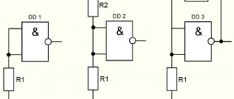
In practice, controlled current sources are devices with four terminals. A control current or voltage is supplied to one pair of terminals, and ideal parameters are taken from the other two terminals, which are a function of the input characteristic. There are four types of such nodes:
- A voltage source that is controlled by voltage. This source is abbreviated as INUN. This is option (a). The input signal goes to the terminals located on the left. The voltage at the terminals on the right is a function of the control voltage.
- Voltage source controlled by current (INUT). Diagram (b) shows that a control current is supplied to the input terminals, and a voltage is removed on the right, which is a function of the current.
- A source controlled by a current that is a function of the control voltage (ITUN). Option (c).
- A source that is controlled by a current that is a function of the control current (ITUT). Option (d).
Electrical circuit and electrical diagram
An electrical circuit is a set of elements and devices designed for the flow of electric current, the electromagnetic processes in which can be described using the concepts of current and voltage.
An electrical diagram is a document compiled in the form of an image that shows the elements of an electrical circuit and their interaction using symbols.
Let's consider two main elements of an electrical circuit: an EMF source and a resistor.
How does an ideal source differ from a real one?
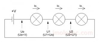
When an ideal current source is considered, it is assumed that it has an infinitely large internal resistance. Therefore, its current is not affected by those parameters of the external electrical circuit on which the voltage at the terminals of the device depends. A real battery behaves differently: the greater the current in it, the smaller the potential difference.
This can be explained as follows. Current represents the ordered movement of charges. When a current source is connected to an electrical circuit, electrons move from one terminal to another. If the current in the circuit is strong, the electromotive force does a worse job of moving carriers inside the battery. This leads to a decrease in the potential difference.
When electrical appliances are connected to the electrical network, they create a load for it. If it is significant, then there is a change in the voltage and current with which the equipment operates.
When an ideal source is considered, the current strength remains independent of voltage. In most cases, we are talking about a constant current strength, although it can vary in accordance with an arbitrary, predetermined function. The presence of a constant characteristic makes it possible to simplify the calculation of the circuit.
In reality, the current flowing through the circuit depends on the load. If it decreases, the current strength can increase sharply. This effect is called short circuiting. To avoid this, fuses are used. If the current is too high, a large amount of thermal energy is released. This causes the fuse to melt and the circuit to break.
A sudden increase in current may cause an accident, but its excessive decrease can also cause an emergency. For example, it may turn out that the current strength is insufficient for normal operation of the device.
Series connection of resistors
Let an electric current I flow through a certain section of the circuit AB, which is only a serial connection of resistors R1...Rk. It is necessary to determine the voltage drop in this section of the circuit and the total electrical resistance of this section.
First, let's find the voltage drop across section AB. Because there are no sources of EMF in the circuit, then according to Ohm’s law, the voltage drop in the i-th section of the circuit is equal to: Summing up the voltage drop in all sections (on all resistors), we obtain: Note that Ф1 = Фa, and Фk = Фb, then: Difference potentials of points A and B by definition (taking into account that the EMF in section AB is equal to zero) is the voltage drop in section AB. We have that: Now, let's determine the total resistance of the circuit section AB. Let's write Ohm's law for section AB: From this formula we express the resistance Rab: Next, remember that the voltage drop in section AB is equal to the sum of the voltage drops across each of the resistors: Now, for each resistor, let's write Ohm's law for a homogeneous section of the circuit: From here: Finally, we substitute the previous expression into the formula for Rab: Conclusion: The total resistance of a section of a circuit when resistors are connected in series is equal to the sum of the resistances of the resistors included in this section (When connected in series, the resistances add up).
How ideal sources are used
Ideal circuits are sometimes used when accurate calculations of real electrical devices are required. In such situations, substitution is made according to strictly defined rules. It is important to follow them so that the result obtained has the required accuracy. Such a replacement is not permissible in all cases, but for a very limited range of electric currents and voltages.
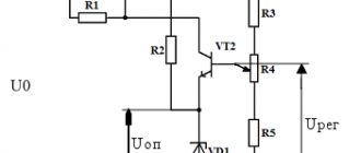
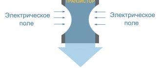
For example, controlled sources have found use in constructing equivalent circuits for semiconductor devices such as transistors. In particular, ITUN can be seen in the equivalent circuit of a field-effect transistor.
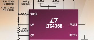
It is impossible to build an ideal IT with infinitely large internal resistance. But in practice, devices based on transistors can be used. Their internal resistance reaches quite large values. Using such current sources, circuits of differential and operational amplifiers and digital-to-analog converters are built.
Parallel connection of resistors
Before moving on to the problem statement, let us introduce an additional definition: A node is a section of an electrical circuit in which more than two conductors converge.
Let current I flow into node A (from the law of conservation of charges it follows that exactly the same current in magnitude flows out of node B). It is necessary to determine the equivalent resistance of circuit section AB. Let us remember that: Consider a sufficiently short period of time during which the current can be considered constant, then: The current through section AB is equal to the ratio of the total charge q passing through a given section of the circuit during time t to this time. At node A the current will be divided into k paths. Charges will move through each resistor. Let charge q1 pass through resistor R1 during time t, charge q2 through R2, …, Rk — qk. Since the law of conservation of charge is satisfied: Divide both expressions by t, we get: We find that the current flowing into a node is equal to the sum of the currents flowing out of this node. More precisely, this rule is formulated as follows: The algebraic sum of currents converging at each node of any circuit is equal to zero - Kirchhoff’s first rule. Next, let's apply Ohm's law for a homogeneous section of the circuit: Note that the voltages on all resistors are the same and equal to U, because Ui = Фa - Фb. We get: Next, we divide the equation by U: As a result, we have obtained a law for finding the equivalent resistance when connecting resistors in parallel.
Conclusion: The reciprocal value of the resistance of a section of a circuit when connecting resistors in parallel is equal to the sum of the reciprocal values of their resistances.
The influence of internal resistance on the properties of a two-terminal network
The higher it is, the less power the source produces when a load is connected. The power in the load can be determined using the formula:
PR = E2/(r+R)2*R,
Where:
- E – EMF voltage;
- R – load resistance;
- r – active internal resistance of a two-terminal network.
The formula is applicable to two-terminal networks that do not release energy.
For your information. When the internal resistance of the two-terminal network approaches the load resistance, the power transfer reaches a maximum.
High internal resistance
Piezoelectric sensors, condenser microphones, and other pulse sources have increased internal impedance. To effectively use such devices, you need to properly match the signal reading circuit. If coordination fails, losses are inevitable.
Important! Successful voltage matching is obtained when using a device with a higher input impedance than that of the signal source to pick up a signal. In the case of a high-impedance source, a buffer amplifier is used to read the signal.
Voltage divider.
A voltage divider is a device whose input and output voltages are connected by a transfer coefficient a, 0 < a < 1. Consider the device of a resistive voltage divider:
Let the electrical circuit consist of an EMF source (E,r) and two resistors R1 and R2. An electric current flows through it, I. It is necessary to find the ratio of the voltage drops across the resistors and their sum.
Let's write Ohm's law for the complete circuit: We know the resistance of the EMF source, it is equal to r. Resistors R1 and R2 form a series connection, so their resistances add up: The current I flowing through the circuit is equal to: Now, apply Ohm's law for the circuit section to R1 and R2: Divide U1 by U2: The ratio of voltages U1 to U2 is equal to the ratio of resistances R1 to R2.
Next, add U1 and U2. We get U12 - the voltage drop on the external section of the circuit: If r is small enough, then the voltage drop on the external section of the circuit is almost equal to the EMF.