What is grounding
The essence of grounding is the deliberate connection of parts of electrical installations and a grounding device (as a rule, these are structures made of metal strips and pins that reduce the voltage level to a value safe for humans).
For understanding, let's look at an example. Let’s say that in any electrical appliance (washing machine, oven or other household appliance), when the insulation breaks down, voltage arises between the device body and the phase. If there is a grounding device, the current will not lead to critical consequences upon contact with a person. This is due to the fact that the protective ground, which has a very low resistance, will act as the priority conductor.
According to their intended purpose, grounding conductors are divided into three classes:
- Lightning protection specializes in lightning voltage removal
- The worker maintains optimal performance of electrical installations under all conditions.
- Protective resists damage to living organisms by high breakdown voltage.
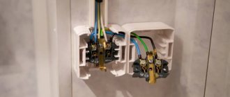
Connecting the circuit to the grounding bus
The main components of the circuit are the ground electrode and grounding conductors. Grounding electrodes can be natural and artificial. In the first case, these are metal structures that have a reliable connection to the ground. Artificial grounding conductors are made of steel rods, pipes or angles, the length of which must be at least 2.5 m. Connected by welded seams, they are driven into the ground. By increasing the number of pipes (angles), you can significantly reduce the resistance of the circuit and make it more efficient.
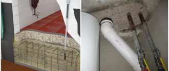
Artificial ground circuit diagram
IT isolated neutral system
In IT, the neutral does not physically have contact with the ground or does, but through devices with high resistance, and the current-carrying elements of the system are grounded.
IT stands for:
I – (from English isolation) isolated neutral;
T – indicates the presence of local (local) grounding of parts of electrical installations;
In such systems, the leakage current to the frame or ground will be quite low and will not affect the operation of the equipment.
IT is used in special-purpose installations with increased requirements for reliability and safety (for example, in hospitals for emergency power supply).
Scheme of work
As mentioned above, grounding is based on provoking a short circuit after a phase hits the metal body of the electrical installation connected to zero. As the current increases, a protective mechanism is activated that cuts off the power supply.
According to the standards of the Electrical Installation Rules, in the event of a violation of the integrity of the line, it must be turned off automatically. The shutdown time is regulated - 0.4 seconds (for 380/220V networks). To disconnect, special conductors are used. For example, in the case of single-phase wiring, the third core of the cable is used.
For correct zeroing, it is important that the phase-zero loop has low resistance. This ensures that the protection is activated within the required period of time.
Organization of grounding requires high qualifications, therefore such work should be performed only by qualified electricians.
Protective grounding
| Item: | Life safety of BZD |
| Kind of work: | Course work |
| Language: | Russian |
| Date added: | 16.03.2019 |
- This type of work is not a scientific work, it is not a finished final qualifying work!
- This type of work is a finished result of processing, structuring and formatting collected information intended for use as a source of material for independent preparation of educational work.
If you have a hard time understanding this topic, write to me on WhatsApp, we’ll look into your topic, agree on a deadline, and I’ll help you!
At this link you can find many ready-made coursework on life safety (LS):
| Lots of ready-made coursework on life safety |
Check out these similar threads, they might be useful to you:
| Protection from electromagnetic fields and radiation |
| Air conditioning system |
| Electromagnetic radiation |
| Means of protection against energy effects |
Introduction:
Protective grounding (grounding) is the main measure for protecting metal structures. The main purpose of this event is to protect the user of the device from possible electrical shock when it is short-circuited, in the event of, for example, electrical shock if a phase conductor is short-circuited due to an insulation break. In other words, grounding is a backup protection for the protective functions of fuses. There is no need to ground all electrical appliances in the house: most of them have a reliable plastic case, which itself protects against electric shock. Protective grounding differs from grounding in that the bodies of machines and devices are not connected to grounding, but to a grounded neutral wire coming from the transformer substation along a four-wire power line. To ensure complete human safety, the resistance of the grounding conductors (together with the circuit) should not exceed 4 Ohms. To do this, they are checked by a special laboratory twice a year (in winter and summer).
Grounding
Grounding is the intentional electrical connection of a point in an electrical network, electrical installation or equipment to a grounding device.
A grounding device consists of a grounding conductor (a conductive part or a set of interconnected conductive parts that are in electrical contact with the ground, directly or through an intermediate conducting medium) and a grounding conductor connecting the grounding part (point) to the grounding conductor. The grounding conductor may be a simple metal rod (most often steel, less often copper) or a complex set of specially shaped elements. The quality of grounding is determined by the resistance value of the grounding device, which can be reduced by increasing the area of the grounding conductors or the conductivity of the medium - using many rods, increasing the salt content in the ground, etc. The electrical resistance of the grounding device is determined by the requirements of the PUE.
Terminology:
- Grounded Neutral - The neutral of a transformer or generator connected directly to a grounding device. The output of a single-phase AC source or pole of a DC source in two-wire networks, as well as the midpoint in three-wire DC networks, may also be dead.
- The isolated neutral-to-neutral of a transformer or generator, not connected to a grounding device or connected to it through high impedance signaling, measuring, protective devices and other similar devices.
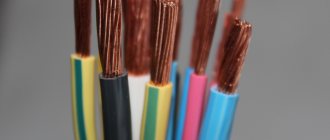
Protective grounding conductors in all electrical installations, as well as neutral protective conductors in electrical installations up to 1 kV with a grounded neutral, including busbars, must have the letter PE (protective grounding) and a color designation with alternating longitudinal or transverse stripes of the same width (for buses from 15 up to 100 mm) yellow and green. Zero working (neutral) conductors are indicated by the letter N and blue. Joint neutral protective and neutral working conductors must have the letter PEN and a color designation: blue along the entire length and yellow-green stripes at the ends.
Grounding system designations.
The first letter in the designation of the grounding system determines the nature of the grounding of the power source:
- T - direct connection of the neutral of the power source to the ground;
- I - all live parts are isolated from the ground.
The second letter determines the state of exposed conductive parts relative to ground:
- T - exposed conductive parts are grounded regardless of the nature of the connection between the power source and the ground;
- N - direct connection of open conductive parts of an electrical installation with a grounded non-neutral power source.
The letters following the line after N determine the nature of this connection - the functional method of constructing zero protective and zero working conductors:
- S - the functions of zero protective PE and zero working N conductors are provided by separate conductors;
- C - the functions of neutral protective and neutral working conductors are provided by one common conductor PEN.
Protective earthing function
The protective effect of grounding is based on two principles:
- Reducing the potential difference between a grounded conductive object and other naturally grounded conductive objects to a safe value.
- Elimination of leakage current when a grounded conductive object comes into contact with a phase conductor. In a properly designed system, the appearance of leakage current leads to the immediate operation of protective devices (residual current devices - RCDs).
Thus, grounding is most effective only in combination with residual current switches. In this case, with most insulation failures, the potential of grounded objects will not exceed dangerous values. In addition, the faulty part of the network will be disconnected for a very short time (tenths or hundredths of seconds is the response time of the RCD).
Protective grounding is used in networks with voltages up to 1000 V AC - three-phase three-wire with a grounded neutral; single-phase two-wire, isolated from ground; two-wire DC networks with an isolated midpoint of the current source windings; in networks over 1000 V AC and DC with any neutral mode.
Grounding is required in all electrical installations with voltages of 380 V and above AC, 440 V and above DC, as well as in hazardous areas, especially dangerous ones, and in outdoor installations with voltages of 42 V and above AC, 110 V and above direct current; at any voltage in hazardous areas.
Depending on the location of the grounding conductors relative to the grounding equipment, there are two types of grounding devices - remote and loop.
When using a remote grounding device, the grounding electrode is moved away from the location of the grounded equipment.
In a loop grounding device, the grounding electrode electrodes are placed along the contour (perimeter) of the site on which the grounded equipment is located, as well as within this site.
In open electrical installations, the enclosures are connected directly to the ground electrode using wires. Buildings have a grounding line to which grounding wires are connected. The ground line is connected to the ground electrode in at least two places.
As grounding conductors, first of all, natural grounding conductors should be used in the form of underground metal communications (with the exception of pipelines for flammable and explosive substances, heating pipes), metal structures of buildings connected to the ground, sheaths of lead cables, casing pipes of artesian wells, wells , quarries, etc.
As natural grounding substations and distribution devices, it is recommended to use grounding supports of outgoing overhead power lines connected to the grounding device of substations or distribution devices using lightning protection cables.
If the resistance of natural grounding conductors Rz meets the required standards, then an artificial grounding device is not required. But this can only be measured. It is impossible to calculate the resistance of natural ground electrodes.
If there are no natural grounding conductors or their use does not produce the desired results, artificial grounding conductors are used - rods made of angle steel measuring 50X50, 60X60, 75X75 mm with a wall thickness of at least 4 mm and a length of 2.5 mm. -3m; steel pipes with a diameter of 50-60 mm, a length of 2.5-3 m with a wall thickness of at least 3.5 mm; Steel rod with a diameter of at least 10 mm and a length of no more than 10 m.
Grounding switches are brought in a row or along the contour to such a depth that from the upper end of the grounding switch to the ground there remains from 0.5 to 0.8 m. The distance between vertical grounding switches must be at least 2.5-3 m.
To connect the vertical grounding electrodes to each other, steel strips with a thickness of at least 4 mm and a cross-section of at least 48 square meters are used. mm or steel wire with a diameter of at least 6 mm. The strips (horizontal ground electrodes) are connected to the vertical ground electrodes by welding. The welding area is covered with bitumen for waterproofing.
Grounding lines inside buildings with electrical installations up to 1000 V are made of steel strip with a cross-section of at least 100 square meters. mm or round steel with the same conductivity. Branches from the main line to electrical installations are made with a steel strip with a cross-section of at least 24 square meters. mm or round steel with a diameter of at least 5 mm.
Grounding takes into account the Earth's ability to conduct electricity. Ground electrodes are usually made of steel. Over time, steel rusts and deteriorates, and the grounding disappears. This process is irreversible, but zinc coated steel rods can be used. Zinc is also a metal, but it does not corrode easily as long as it has a layer of zinc on it.
When zinc is washed or mechanically washed over time, for example when electrodes are driven into hard soil, the stones can peel away from the coating, then the corrosion rate doubles. Sometimes special copper-plated electrodes are used.
The ground rods can be those that were used as reinforcement for a concrete foundation. They cannot be painted or coated with resin - the resin will act as an insulator and there will be no grounding at all. The longer the rods, the less they will be needed for grounding, but the more difficult it is to drive them into the soil. Therefore, you first need to dig a trench 1 meter deep. Hammer a piece of reinforcement into the trench, previously polished, so that it protrudes from under the bottom of the trench no more than 20 centimeters. After 2 meters, the next reinforcement is hammered in and so on, according to calculation. Next, the reinforcement is laid at the bottom of the trench and welded to all clogged pins. The welding area must be covered with bitumen for waterproofing. This is due to the fact that reinforcement 12 millimeters thick will rot in the ground for a very long time, but the welding site is relatively small, but most important.
Once all the electrodes are clogged, you can experiment. We take out the extension cord from the house. The voltage source must come from the pole from the substation. It is not possible to use a stand-alone source such as a generator for testing - there will be no closed circuit. We find a phase on the extension cord and connect one wire from the light bulb, and touch the second wire to the scalded electrodes. If the lamp is on, then we measure the voltage between the phase conductor and the grounded electrodes, the voltage should be 220 V, but the lamp should be bright enough. It is also possible to measure current through a 100 W light bulb. If the current is approximately 0.45A, everything is fine, but if the current is much less, add ground rods.
It is necessary to achieve a normal glow of the bulb and the current within normal limits. After this, the welding site is filled with bitumen and a piece of reinforcement is removed from the trench, attaching it to the house. After this, the trench can be backfilled. The removed piece of reinforcement must be welded to the electrical panel in the cottage. On the screen, already indicate all the points with copper cables.
Types of grounding systems
As the main characteristic of the electrical network, a classification of types of grounding systems is given. GOST R 50571.2-94 “Electrical installations of buildings.
TN-C In the 1930s, the TN-S system (French Terre-Neutre-Separe) was developed, the working and protective zero of which were separated directly at the substation, and the grounding electrode was a rather complex structure made of metal reinforcement. Thus, when the working zero was cut in the middle of the line, the electrical cabinets did not receive mains voltage. Later, such a grounding system made it possible to develop differential and leakage machines capable of accepting small currents. Their work to this day is based on Kirchhoff's laws, according to which the current flowing through the phase wire must be numerically equal to the current flowing through the working zero.
You can also observe the TN-CS system, where the separation of zeros occurs in the middle of the line, however, in the event of a break in the neutral wire before the separation point, the cases will be under line voltage, which will pose a threat to life if touched.
In the TN-CS system, the transformer substation has a direct connection of live parts to the ground. All exposed conductive parts of the building's electrical installation are directly connected to the grounding point of the transformer substation. To make this connection, the transformer substation uses an electrical neutral conductor and a service conductor (PEN), and a separate neutral conductor (PE) is used in the main part of the electrical circuit.
In the TT system, the transformer substation has a direct connection of live parts to the ground. All exposed conductive parts of the building's electrical equipment are directly connected to the ground through a ground electrode, which is independent of the neutral grounding of the transformer substation.
In an IT system, the neutral of the power supply is isolated from earth or earthed through high-impedance devices or devices, and the exposed conductive parts are earthed. The chassis or ground leakage current in such a system will be low and will not affect the operating conditions of the connected equipment. An IT system is typically used in electrical installations of special-purpose buildings and structures that have increased requirements for reliability and safety, for example, in hospitals for emergency power supply and lighting.
Reset
Zeroing is the deliberate electrical connection of exposed conductive parts of electrical installations that are not in a normal energized state with the grounded neutral point of a generator or transformer in three-phase current networks; with a grounded output of a single-phase current source; with a grounded source point in DC networks, designed for electrical safety. Protective grounding is the main measure of protection against indirect contact in electrical installations with voltages up to 1 kV with a grounded neutral.
The principle of grounding: if the voltage (phase) drops across the metal body of a device connected to zero, a short circuit occurs. The circuit breaker connected to the faulty circuit short-circuits and cuts off power to the line. In addition, the fuse can cut off power from the line. In any case, PUE regulate the time for automatic shutdown of a damaged line. For the rated phase voltage of the network 380/220 V, it should not exceed 0.4 s.
Zeroing is carried out by specially designed conductors. In single-phase wiring, this is, for example, the third core of a wire or cable. In order for the protective device to turn off at the moment determined by the rules, the resistance of the phase-zero loop must be small, which, in turn, imposes strict requirements on the quality of all connections and network installation, otherwise zeroing may be ineffective. In addition to quickly disconnecting the faulty line from the power source, because the neutral is grounded, grounding provides a low touch voltage to the device body. This eliminates the possibility of electric shock.
Nullification is used to turn off a damaged energy receiver as quickly as possible in the event of a housing failure, thereby limiting the minimum possible time during which the damaged object will pose a danger to personnel. When zeroing, the damaged electrical receiver is switched off under the action of the fault current on the housing in the line supplying the damaged electrical receiver.
For fast and reliable operation of overcurrent protection, the ratio of the fault current to the frame relative to the protection setting current should be as large as possible.
The PUE requires (clause 1.7.79): that the single-phase circuit current to the housing:
- exceeded - no less than 3 times the rated current of the fuse insert of the nearest fuse;
- not less than 3 times higher than the current setting of the circuit breaker release, which has a characteristic inversely dependent on the current;
- not less than 1.1 Cr, the instantaneous current of the machine, which has only a release without a time delay, where Kr is a coefficient that takes into account the spread of operating currents (according to factory data). In the absence of factory data on the magnitude of the spread, the short-circuit current multiplicity relative to the specified value should be taken as 1.4 for machines with voltages up to 100 A and 1.25 for machines with a rated current of more than 100 A.
In hazardous installations (PUE, clause 7.3.139), the above multiples of the single-phase frame fault current must be increased to 4 in the fused circuit; up to 6 in a circuit protected by a circuit breaker with an inverse current characteristic. In circuits protected by a circuit breaker that has only electromagnetic (instantaneous) shutdown, the current ratio of a single-phase circuit to the housing is determined as for non-hazardous installations.
Zero protective conductors.
Zero protective conductors can serve as:
- individual (including neutral) cores of multicore wires and cables;
- specially laid conductors;
- elements of metal structures of buildings, steel electrical wiring pipes, metal structures for industrial purposes, pipelines for any purpose (except for pipelines of flammable and explosive mixtures) laid openly;
- aluminum cable sheaths.
Grounding and neutral protective conductors must be protected from corrosion. The weld seams must be painted after welding. In dry rooms, asphalt varnish, oil paints or nitro enamels should be used for this. In damp rooms and rooms with caustic vapors, painting should be done with paints that are resistant to chemical influences (for example, polyvinyl chloride enamels).
It is prohibited to use metal sheaths of tubular wires carrying cable laying ropes, metal sheaths of insulating tubes, metal hoses, armored and lead sheaths of wires and cables as grounding or neutral protective conductors.
In electrical installations with voltages up to 1000 V with a grounded neutral, neutral protective conductors must be laid along with the phase or in close proximity to them in order to reduce the inductive reactance of the phase-zero circuit.
Branches from the main line to electricity consumers up to 1 kV can be laid hidden directly in the wall, under a clean floor, etc. With their protection from an aggressive environment. Such branches should not have connections.
The laying of grounding and neutral protective conductors through walls should be carried out in open holes, in non-metallic pipes or other rigid frames.
In dry rooms, without an aggressive environment, grounding and neutral protective conductors can be laid directly on the walls. In damp, damp and especially damp rooms, as well as in rooms with an aggressive environment, grounding and neutral protective conductors must be laid at a distance of at least 10 mm from the walls. The distance between the supports for mounting the grounding and neutral protective conductors should be no more than 1000 mm.
In outdoor installations, grounding and neutral protective conductors can be laid in the ground, on the floor or along the edge of platforms, foundations of technological installations, etc.
The use of bare aluminum conductors in the ground as grounding or neutral protective conductors is prohibited.
Each part of the installation subject to earthing or grounding must be connected to the earthing or earthing network using a separate branch. The sequential connection of grounded or neutralized parts of an electrical installation to the grounding or neutral protective conductor is not allowed.
Grounding switches must be connected to the grounding lines with at least two conductors connected to the grounding switch at different locations. This requirement does not apply to re-grounding the neutral wire and metal sheaths of cables.
The connection of the parts of the grounding electrode to each other, as well as the grounding electrode to the grounding conductors, must be performed by welding; The length of the overlap should be equal to the width of the conductor with a rectangular cross-section and six diameters with a round cross-section. When two strips overlap in a T-shape, the length of the overlap is determined by the width of the strip.
The use of specially laid grounding or neutral protective conductors for any purpose is not permitted.
Exposed grounding and neutral protective conductors must have a characteristic color: yellow stripes on a green background.
When using building or technological structures as grounding or neutral protective conductors, two yellow stripes must be applied to the bridges between them, as well as at the points of connection and branching of conductors, on a green background at a distance of 150 mm from each other.
Connections of earthing and neutral protective conductors to parts of equipment subject to earthing or grounding shall be made by welding or bolting. The connection must be accessible for inspection.
For bolted connections, measures must be taken against loosening of the contact connection (lock nut, split spring washer, etc.) and corrosion (lubrication with a thin layer of Vaseline coating on contact surfaces that have been cleaned to a metallic shine, etc.).
The resistance of the neutral protective conductors has a decisive influence on the overall resistance of the ground circuit and, consequently, on the magnitude of the fault current in the enclosure. Of the neutral protective conductors listed above, only the conductor resistance of wires and cables can be calculated analytically.
Calculation of zero protective conductors for heating. Neutral protective conductors must transmit single-phase fault current into the housing without damage. This requirement is considered fulfilled if the conductivity of the protective conductor at any point is at least 50% of the conductivity of the phase conductors.
A two-phase short circuit current can flow through neutral protective conductors only in the event of a simultaneous short circuit to the housing of various energy consumers and in different phases. When choosing the cross-section of neutral protective conductors, this case is not taken into account.
Elements of metal structures of buildings, steel electrical wiring pipes, industrial structures and pipelines used as neutral protective conductors are not tested for resistance to short circuits on the housing.
The cross-section of the aluminum sheath of the cables in almost all cases exceeds the cross-section of the phase wire, so it can be considered stable under short-circuit currents on the housing.
Zero working conductors
To power electrical receivers with a single-phase or non-uniform three-phase load, it is necessary to lay a working neutral wire along which the geometric sum of phase currents flows. The neutral working wire is connected to the neutral of the generator or the secondary winding of the transformer, and can be used to zero the receiver housing. The working current flows for a long time along the working neutral wire, which creates a voltage drop in it, and therefore it must be insulated along its entire length when used for grounding (as a protective one).
If a neutral conductor is used as a protective conductor, the requirements applicable to neutral protective conductors apply.
Neutral working conductors must be designed for continuous supply of operating current.
As neutral working conductors, it is recommended to use conductors with insulation equal to the insulation of phase conductors. Such insulation is required for both neutral conductors and neutral protective conductors in those locations where the use of bare conductors could result in electrical couples or damage to the insulation of phase conductors as a result of arcing between the bare conductors and the sheath or structure (for example, when laying wires in pipes, boxes, trays).
It is not allowed to use neutral working conductors going to portable electrical receivers of single-phase and direct current as neutral protective conductors. To reset portable electrical receivers, it is necessary to use a separate third wire connected through a plug-in connector (connector) to the neutral working or neutral protective conductor.
Types of grounding systems
There are neutralization systems TN-C, TN-CS and TN-S.
TN-C grounding system
A simple grounding system in which the neutral conductor N and the protective neutral PE are combined along their entire length. The connecting conductor is abbreviated as PEN. It has significant disadvantages, the main of which are the high requirements for potential equalization systems and the PEN conductor cross-section. It is used to power three-phase loads such as induction motors. The use of this system in single-phase group and distribution networks is prohibited:
Combining the functions of the neutral protective and neutral working conductors in single-phase circuits and DC circuits is not allowed. A separate third conductor must be provided as a neutral protective conductor in such circuits.
Grounding system TN-CS
An advanced grounding system designed to ensure electrical safety of single-phase electrical installation networks. It consists of a PEN composite conductor which is connected to the grounded neutral supplying the transformer. At the point where a three-phase line branches into single-phase consumers (for example, on the floor of an apartment building or in the basement of such a house), the PEN conductor is divided into PE and N conductors, which are directly suitable for single-phase consumers.
Grounding system TN-S
The most modern, expensive and safe grounding system, which has become widespread, particularly in the UK. In this system, the neutral protective and neutral conductors are separated along their entire length, which eliminates the possibility of its failure in the event of an accident on the line or an error during the installation of electrical wiring.
Conclusion:
Ensuring life safety is a priority for the individual, society and the state. From the moment of his appearance on Earth, man constantly lives and acts in conditions of constantly changing potential dangers. Being aware in space and time, dangers cause harm to human health, which manifests itself in nervous shocks, illnesses, disabilities, deaths, etc. Prevention and protection from them is the most pressing humane, socio-economic and legal problem in which the state does not may not be interested. To ensure electrical safety, it is necessary to strictly implement a number of organizational and technical measures established by the rules for the installation of electrical installations, the rules for the technical operation of consumer electrical installations and the safety rules for the operation of electrical installations. consumer installations. Dangerous and harmful effects on people of electric current, electric arc and electromagnetic fields manifest themselves in the form of electrical injuries and occupational diseases. Electrical safety in the premises is ensured by technical methods and means of protection, as well as organizational and technical measures.
What is zeroing: principle of operation and device
Grounding is installed according to a different principle. But to sort this out, let’s look at what a solidly grounded neutral is. 3 phases arrive at the transformer substation via power lines. The own grounding, mounted around, is a solidly grounded neutral, which goes to residential buildings from the substation, along with the phase wires.
Zeroing is done like this. Wiring is made in the distribution board, the solidly grounded neutral (PEN) coming from the transformer substations is broken in front of the input circuit breaker into a zero (N), going to the apartment, and what can be considered ground (PE). In fact, in essence, this will remain a solidly grounded neutral, which will be used for grounding. Worker N is prohibited from zeroing the equipment - this is dangerous to life. If everything is done correctly, then when the body of the switched-on device comes into contact with a live, bare wire, a short circuit occurs, after which the machine is triggered.
The simplest scheme for zeroing an apartment electrical network
Expert opinion Igor Marmazov ES, EM, EO design engineer (power supply, electrical equipment, interior lighting) ASP North-West LLC
“Protective grounding is a system that is installed to instantly trigger the automation when voltage appears on the device body and completely shuts off the power.”
Only a complete understanding of what grounding and grounding are, what their features are, will make it possible to implement the type of protection in an apartment or house that will be effective and safe.
Operating principle
The grounding circuit of an electrical circuit is a system of wires that connects each consumer in the serviced circuit with a special grounding circuit of the building. In the event of a breakdown on the device body or current leakage from damaged wiring, the current flows through the wires to the ground electrode.
The grounding resistance is usually less than the resistance of the entire circuit. Therefore, the current flows along the “easy” path and is removed from the equipment housings.
Grounding is the electrical connection of conductive housings of devices with a solidly grounded neutral. When peak current values occur, its potential is diverted, using a grounding bus, to a special switchboard or transformer booth.
Its main purpose is in cases of breakdowns and voltage leaks on the equipment body, causing a short circuit, blowing fuses or tripping automatic circuit breakers.
This is the main difference between grounding and grounding. The grounding circuit absorbs short-circuit currents; grounding causes the safety devices to operate.
Let us examine in more detail the operation of protection systems against the effects of electric current.
Zeroing systems and schemes
There are several options for protecting electrical equipment by grounding the metal casing of the device. In this article we will look at the following two main methods of grounding any equipment connected to a three-phase and single-phase power supply network.
- Three-phase network. For such a connection, the circuit is quite simple and it will not be difficult for anyone familiar with the basics of electrical engineering. In this embodiment, the neutral wire N and the protective line PE are combined into one common bus called PEN. This zeroing method is called the TN-C system. To implement it, it is necessary to strictly comply with the increased requirements for equalizing electrical potentials, as well as for the cross-sectional area of the combined PEN conductor. For networks with a single-phase power supply, the use of the TN-C system is strictly prohibited by the electrical installation rules (PUE).
- Single-phase network. To implement protective grounding in single-phase networks, there is a method using the TN-CS system. With this method, the N conductor is combined with the PE line only in a limited section of the power supply network, starting next to the main power source. The TN-CS system is good for single-phase networks, but in no case should it be used when grounding electrical equipment operating in three-phase electrification networks.
Any protective grounding system can only be used in networks, both single-phase and three-phase, with an alternating voltage of no more than 1 kV, moreover, the network must necessarily have a tightly grounded neutral. After completing work to protect electrical equipment, it is necessary to check and calculate the zeroing system, which should only be entrusted to a specialist, since this procedure involves the use of special instruments. As a result of the measurements, the resistance of the neutral-phase loop is determined, which should have a minimum value.
After this, according to Ohm’s law, according to which I = U/R, the short-circuit current (short circuit) is calculated when a network phase hits the metal body of the device. The value of this parameter should be a certain amount greater than the triggering threshold of automatic electrical de-energization systems. Otherwise, they need to be replaced with devices with a lower response threshold or measures must be taken to reduce the resistance value of the neutral-phase loop. When calculating the short-circuit current, an increasing reliability factor Kn should be used, which is always greater than one.
Systems with solidly grounded neutral TN grounding system
Such systems include:
- TN-C;
- TN-S;
- TNC-S;
- TT.
According to clause 1.7.3 of the PUE, a TN system is a system in which the neutral of the power source is solidly grounded, and the open conductive parts of the electrical installation are connected to the solidly grounded neutral of the source through neutral protective conductors.
TN includes elements such as:
- grounding electrode of the middle point, which relates to the power source;
- external conductive parts of the device;
- neutral type conductor;
- combined conductors.
The source neutral is solidly grounded, and the external conductors of the installation are connected to the solidly grounded midpoint of the source using protective type conductors.
It is possible to make a grounding loop only in electrical installations whose power does not exceed 1 kV.
TN-C system
In this system, the neutral protective and neutral working conductors are combined into one PEN conductor. They are combined throughout the system. The full name is Terre-Neutre-Combine.
Among the advantages of TN-C, one can highlight only the easy installation of the system, which does not require much effort and money. Installation does not require improvement of already installed cable and overhead power lines, which have only 4 conducting devices.
Flaws:
- the likelihood of receiving an electric shock increases;
- it is possible that line voltage may appear on the body of the electrical installation during an electrical circuit break;
- high probability of loss of the grounding circuit in case of damage to the conductive device;
- This system only protects against short circuits.
TN-S system
The peculiarity of the system is that electricity is supplied to consumers through 5 conductors in a three-phase network and through 3 conductors in a single-phase network.
In total, 5 conductive sources leave the network, 3 of which serve as the power phase, and the remaining 2 are neutral conductors connected to the zero point.
Design:
- PN is a neutral mechanism that is involved in the circuit of electrical equipment.
- PE is a solidly grounded conductor that performs a protective function.
Advantages:
- ease of installation;
- low cost of purchasing and maintaining the system;
- high degree of electrical safety;
- no contour creation required;
- the ability to use the system as a current leakage protection device.
TN-CS system
The TN-CS system involves dividing the PEN conductor into PE and N in some part of the circuit. Usually the separation occurs in the panel in the house, and before that they are combined.
Advantages:
- simple design of a protective mechanism against lightning strikes;
- availability of short circuit protection.
Disadvantages of use:
- poor level of protection against burning of the neutral conductor;
- possibility of phase voltage occurrence;
- high cost of installation and maintenance;
- the voltage cannot be turned off automatically;
- There is no protection against current in the open air.
TT system
TT is designed to provide a high level of safety. Installed in power plants with a low level of technical condition, for example, where bare wires are used, electrical installations that are located in the open air or mounted on supports.
TT is mounted according to a four-conductor circuit:
- The 3 phases supplying voltage are shifted at an angle of 120° to each other;
- 1 common zero performs the combined functions of a working and protective conductor.
TT advantages:
- high level of resistance to deformation of the wire leading to the consumer;
- short circuit protection;
- Possibility of use on high voltage electrical installations.
Flaws:
- complex lightning protection device;
- inability to track the phases of a short circuit in an electrical circuit.
Operating principle of RCD
For the safe operation of industrial and household equipment, residual current devices (RCDs) are used, and devices of automatic differential switches are used. Their work is based on comparing the electric current entering through the phase wire and leaving the apartment through the neutral conductor.
The normal operating mode of an electrical circuit shows the same current values in the named sections, the flows are directed in opposite directions. In order for them to continue to balance their actions, ensure balanced operation of the devices, they carry out the installation and installation of grounding and grounding.
A breakdown in any section of the insulation leads to the flow of current directed to the ground through the damaged area, bypassing the working neutral conductor. The RCD shows an imbalance of current, the device automatically turns off the contacts and the voltage disappears in the entire operating circuit.
For each individual operating condition, different settings are provided for turning off the RCD, usually the setting range is from 10 to 300 milliamps. The device operates quickly, the shutdown time is seconds.
Zeroing: purpose and characteristics
Grounding instead of grounding is often used in apartments where there is no traditional grounding system or it has an outdated appearance. This type of protection involves connecting metal parts that do not conduct current with a solidly grounded neutral conductor. This mechanism is designed so that when the insulation is damaged and current exits to the device body, a short circuit occurs, as a result of which circuit breakers and RCDs are triggered.
Important! When practicing grounding instead of grounding, be sure to install automatic circuit breakers and residual current devices. You should carefully and regularly check the neutral wire, since in the event of a high current output, all devices that are grounded are energized
This situation is explained by the automatic switching of zeroed devices to phase. Therefore, for safety reasons, it is not recommended to connect automatic devices and other protective equipment to zero. However, you can completely protect yourself from electric shock only by installing repeated grounding conductors for every 200 m of the electrical network
You should carefully and regularly check the neutral wire, since in the event of a high current output, all devices that have been grounded are energized. This situation is explained by the automatic switching of zeroed devices to phase. Therefore, for safety reasons, it is not recommended to connect automatic devices and other protective equipment to zero. However, you can completely protect yourself from electric shock only by installing repeated grounding conductors for every 200 m of the electrical network.
What's better?
In order for you to fully understand the material, we will first provide the differences in the use of each system, on the basis of which we will draw our own conclusion.
- Grounding a house can easily be done with your own hands, having a welding machine and some metal on hand. At the same time, creating a grounding requires certain knowledge related to calculations and selection of the optimal point for connecting the wire to the neutral.
- The conductor that provides the indicated connections of the grounded parts with the solidly grounded neutral of the source is called the neutral protective conductor.
- The neutral protective conductor differs from the neutral working conductor, which is also connected to a solidly grounded neutral point of the source. It is intended to supply power to the source.
- If the neutral wire in the distribution panel breaks, the neutralizing system will not work and you may become a victim of electric shock. In this regard, it is easier with a protective grounding system, because Unlike zero, the PE wire does not burn out and practically does not fall off if the terminal is tightened at least once a year. Although we can say about this that the “ground” circuit, due to the fact that it is located on the street, can also be damaged over time, especially in the places where the electrodes are welded. Again, if you do an annual audit, there will be no problems.
Based on this, we can draw the following conclusion: proper grounding in a private house is not difficult to do with your own hands, and besides, such a system is more durable, and therefore safer. As for grounding, to create it you need to call a specialist and, at the same time, more frequently inspect the integrity of the neutral wire, which is a huge disadvantage when comparing the differences. This option is not recommended; it is better to connect an RCD for protection. We hope that now you understand the difference between grounding and grounding, how both systems work and which is more effective for a house or apartment.
Distinctive features - part 1
Distinctive features - part 2
Related materials:
- How to replace electrical wiring in an apartment
- How to make grounding in an apartment with your own hands
- How to find a wire in the wall
How to connect grounding?
How to connect grounding?
An integral part of modern life is electrical wiring with grounding. Of course, you can connect to the network without grounding, because for so long we somehow managed without it.
But when modern household appliances appeared, this condition became mandatory in order to protect people from the negative effects of electricity. Many modern electrical appliances are already available with a grounding terminal. In new buildings, all wiring is done taking it into account.
But in old apartments and private houses it is usually absent. We will tell you in this article how to properly connect grounding if there is none in the room.
How did you do it before?
According to former Soviet standards, it was almost always shorted to the “zero” wire. If the wiring needs to be grounded in an old apartment building, where there is simply no third wire in the wiring, you should do as in the old days: connect the “ground” to the “zero”.
What not to do?
This is how to connect the ground to heating radiators or to a cast iron or metal bathtub. It is very dangerous to do this both in an apartment building and in a private house, since electrical appliances can “break through” onto metal pipes.
Especially if there are several switched on mechanisms: it can give a good shock when touching the heating system. Taking a bath can also give you an invigorating boost. So it's better to never try this.
Imagine that your neighbor downstairs replaced metal pipes with plastic ones, and you were left without grounding, without knowing it!
What is grounding?
This is the deliberate connection of an electrical network to a device that grounds it.
It is intended to drain current leakage that occurs on the housings of household appliances during emergency mode and provides conditions for disconnecting the voltage by automatically triggering the protection device.
If the equipment is protected in this way, then when a person touches the household appliance, the current remaining on the housing will not be dangerous to the body. If the equipment is not grounded, current will flow through the human body (although not completely, but you will certainly feel it).
In a private house
It is easier to build grounding in a private house using a special grounding conductor - a metal rod or object that has direct contact with the soil. A wire grounding the electrical network is attached to it.
After this, switched on household appliances will not receive electric shock. It is only important that the grounding device is periodically checked with a special device and complies with standard standards.
For more information about where to get grounding to connect a lighting device, read the article Where to get grounding to connect a lamp.
Source: https://elhow.ru/bytovye-sovety/remont/elektrika/kak-podkljuchit-zazemlenie
Grounding tasks
The artificially created contact between the electrical installation and the ground is called grounding. Its task is to reduce the voltage on the device body to a level that is safe for living beings. In this case, most of the current is diverted into the ground. For the grounding system to work effectively, its resistance must be significantly lower than that of the rest of the circuit. This requirement is based on the property of electric current to always choose the least resistance along its path.
The fault current is sometimes insufficient when using a ground electrode with a relatively high resistance for the response of protective devices. Therefore, another task of the grounding system is the increase in emergency fault current.
Types of grounding devices:
- Lightning protection. Pulse currents entering the system as a result of lightning strikes are removed. Used in lightning rods and arresters.
- Workers. Designed to maintain normal operation of electrical installations. Used in both normal and emergency situations.
- Protective. They protect people and animals from electric shock passing through metal objects in the event of breakdown of phase conductors.
Grounding devices can be natural or artificial:
- Natural products include metal products whose main function is not to drain current into the ground. Such grounding conductors include pipelines, reinforced concrete elements of buildings, casing lines, etc.
- Artificial ground electrodes are systems created specifically for current drainage. These are steel strips, pipes, corners and other metal elements.
For the grounding system, you cannot use pipes intended for transporting flammable substances (both gases and liquids), aluminum parts, and cable sheaths. Objects coated with an anti-corrosion insulating layer are also not suitable for this purpose. It is prohibited to use water supply and heating pipes as grounding conductors.
Grounding concept
Before answering the question of how grounding differs from grounding, let’s consider each concept separately. Grounding is a special connection of electrical installations to the ground. The purpose of this connection is to reduce sudden voltage surges in the electrical network. It is used in the circuit where the neutral will be isolated. When suitable grounding equipment is installed, the excess current that enters the network will flow into the ground through the outlet contacts. The resistance of this part must be relatively low so that the current is completely absorbed.
Also, the function of protective grounding of electrical installations allows you to increase the volume of emergency fault current, despite the fact that this contradicts its purpose. A grounding electrode with high resistance may not be able to withstand a weak fault current, only with special protective devices. In this case, when there is an emergency, the installation will be energized, which can pose a great danger to human health in this room. The purpose of protective electrical installations is also designed to remove stray current in the electrical network.
The ground electrode is a special conductor that may consist of one or more elements. They are usually connected to each other by electrically conductive material and are embedded in the ground, which absorbs the passing charge. Steel and copper can be used as grounding conductors. According to the PUE standards, this protective measure must be taken in modern residential buildings, as well as work premises, factories, public institutions and other buildings for various purposes.
Most modern homes have grounding circuits installed. However, they may not be present in older buildings. In such a situation, experts recommend replacing the wiring with a three-core cable with a grounding wire, connecting a protective electrical installation. There are situations when it is not possible to install a complete grounding loop. In modern electrical engineering, special portable equipment can be used - a portable grounding pin (bus). Their action corresponds to the standard grounding device of residential buildings or taps. Such a device has good practical value, is easy to install, carry, repair, and also has a wide range of functionality.
The grounding function can be performed by several independent groups of protective equipment. Lightning protection. They serve to quickly remove high pulsed charge from lightning. Often their use is necessary in arresters and modern lightning rods. Workers. This group allows you to maintain the required operation of all electrical installations under different conditions (normal and emergency).
Protective. This group of equipment is needed to prevent direct contact of people and animals with an electrical charge that occurs as a result of mechanical damage to a phase in the wire. They prevent many accidents that could occur if problems with the power line were not noticed in a timely manner.
Grounding electrodes are conventionally divided into artificial and natural. Artificial electrical installations are special structures that I make specifically in order to divert excess network current into the ground, providing protection for my home. They can be produced in a factory or made independently using steel elements. Natural grounding conductors are the soil, the foundation under a building, or a tree near the house.
System reliability
The grounding system is more reliable.
The grounding conductor does not participate in the operation of the network; it is connected only when a current leak occurs and discharges it to the ground. The bad part is the area where the ground conductor is connected to the ground loop. A current may spread here, and an area within a radius of 20 meters may be dangerous. Grounding becomes dangerous if the neutral wire breaks or burns out. In this case, no protection is effective and the person may become energized. It is necessary to carefully inspect the contacts of the neutral conductor.
With a three-phase connection, the installation of protective systems is carried out in the following way. Zero will be the neutral terminal of the transformer. The neutral will have contact with the ground within the transformer substation. Connecting electrical equipment goes through the following stages:
- A line made of metal strip or copper wire is laid along the perimeter of the production premises.
- A copper busbar with holes for bolts is mounted on it. You can use metal tires, but in this case it is necessary to weld studs to them.
- The line is connected to the grounding or grounding circuit with a separate wire. The housings of all consumers are connected to the bus with a copper wire.
Difference in comparison
You don't have to be an electrician to understand the differences between these devices. It is enough to understand the essence of their purpose. If one diverts dangerous voltage into the ground, then the other equalizes it to safe levels.
Proper connection of electrical equipment and electrical appliances prevents electric shock. In an extreme situation, a short circuit occurs on the housing. The protection is triggered and disconnects the electrical circuit. In this case, grounding works. The earth is used as a conductor.
There was voltage in the house, on the heating device. A dangerous situation must be prevented by grounding. But the pipes between the apartment and the basement were changed: plastic ones were installed instead of steel ones. They disconnected the conductor. Grounding didn't work. The SUP eliminated the electrical potential difference using conductors. The danger has been eliminated.
Comparing these devices helps to understand the differences between them:
- SUP is the electrical connection of metal structures with each other and the ground. They have equal potential.
- Grounding - connection of all metal parts with a ground electrode.
- The potential equation concerns only structures that may be energized among themselves.
- Grounding concerns only the drainage of currents into the ground.
- The purpose of the control system is to equalize the potentials of the conductive parts among themselves: to make them safe for the lives of people and animals.
- The purpose of grounding is to equalize the potentials of grounded parts of equipment with the ground potential.
They can be called comprehensive protection against electric charge. But before installing a potential equalization system in your house, call an electrician, read the PUE, look at the house construction project. What grounding system is it built with?
For example, with TN-C and a combined PEN conductor, DSUP is prohibited. Reconstruction with transition to the TN-CS system is required.
Why is grounding necessary?
If the energy supply in the room is organized in accordance with the PUE, circuit breakers are installed at the entrance, in the distribution panel.
These switches are triggered when the set current strength is exceeded: the bimetallic plate heats up, it deforms, and the contacts of the machine mechanically open.
When a live circuit breaks, the electrical installation (or the entire circuit) is de-energized, ensuring safety. How does this work in practice, and what is grounding in this chain?
Grounding is an electrical contact between a line specially allocated in the electrical network and the real (physical) ground. That is, the grounding bus has electrical contact with the ground. At the same time, any installation that generates or distributes electric current is connected by a neutral wire to the same ground.
Even if three phases are installed in your house (this occurs in the private sector), for final consumption two wires are still used: zero and phase.
Let's say your electrical installation (refrigerator, boiler, washing machine), especially with a metal body, has a phase leak. That is, the live wire touches the housing (the contact is disconnected, the insulation is broken, water leaks). If you touch an electrical appliance, you will receive an electric shock. In addition, the resistance at the point of contact is negligible, as a result of which the wire will instantly heat up and the electrical appliance will ignite.
If your boiler is grounded, the electric current will flow along the path of least resistance, that is, along the circuit: phase - “ground” - zero bus. The current will spontaneously increase and an emergency shutdown will be triggered in the circuit breaker. No one will get hurt, no material damage will be caused.
If you have a superficial knowledge of electrical installations, the question arises: why do you need grounding if the same thing happens between the phase and neutral wires? And actually, what is the difference between grounding and grounding?
In what cases is protection required?
When there is physical (more precisely, electrical) contact with the body of a phase conductor, or a circuit element to which voltage is currently applied, two dangers arise:
- Electric shock. In case of accidental or intentional (occurring during operation of the installation) touch, electric current will flow through your body. A potential difference arises between the phase and the “ground” (in the literal sense of the word), and you act as a conductor. The resistance of the human body is not so great, especially if the skin is moistened by sweat. Therefore, the strength of the current flowing through you is sufficient to cause damage to health, and in some cases leads to death;
Short circuit through electrical installation components. If voltage appears in an unauthorized area of the circuit, at a minimum, the electrical appliance may suffer. Restoring is sometimes more expensive than buying a new one. If the integrity of the wiring is damaged, a fire often occurs. The current flowing through wires with low resistance reaches a value that can ignite the insulation and other elements of the circuit.
The system of grounding and grounding of electrical equipment provides protection against the considered hazards, or at least minimizes the consequences. Many inexperienced home-grown electricians confuse these two concepts. Or they deliberately use the working zero when organizing grounding.
This is especially true in old high-rise buildings, where a separate grounding loop is not provided. If the power supply lines are fully operational, this is not so dangerous. However, if the neutral wire on the main line is damaged, or the contact at the terminal connections deteriorates, the working zero loses electrical connection with the real “ground”.
You rely on phase protection and work with an electrical appliance without fear. At a critical moment, the protection does not work, and in the best case, equipment damage occurs, and in the worst case, a fire or electric shock occurs.
Important! Using a working zero to protect users is prohibited!
Protective grounding and grounding are fundamentally different in the way they are connected to the physical ground. If you use zero as grounding, troubles can happen:
- For example, you grounded the boiler to working zero. In the event of a phase breakdown on the housing, the residual current device (RCD) may not operate. Through water, from a hot tap, tension is transferred to you. If you are in the bathroom, you will be exposed to a life-threatening electrical current;
- You are using an electric stove located next to the radiator. The hot water supply system is laid in the ground and has reliable contact with the ground. If the electric stove is not grounded or is grounded to zero, if the neutral wire is damaged, a phase may appear on the body. If your hands touch the live housing and the grounded battery at the same time, electric shock is guaranteed.
When should you use grounding and when should you use grounding?
In this part of the article we will answer the question of what is the difference between grounding and grounding and in what case to use one or another method of protecting a person from electric shock. The operating principle of protective grounding is similar to the functionality of grounding, but there is a significant difference between them!
Both systems are designed to protect people from electrical shock. The difference between them is that grounding instantly de-energizes the equipment, while grounding drains dangerous electric current into the ground. This is where the whole difference lies! The diagram below clearly shows the differences between these two methods.
Which method is best to use in each specific case? It is impossible to answer this question unambiguously. For example, in multi-story buildings, creating a ground loop is a difficult and expensive undertaking. Therefore, most apartments use protective grounding, which is connected to household appliances through electrical outlets. In a private house, installing a grounding loop will not cause any difficulties. Each of the protection systems has the following advantages and disadvantages.
- Grounding in a private house can be done with your own hands, and grounding requires knowledge of electrical engineering, carrying out calculations and choosing the optimal connection option to the neutral wire of the power supply system. In addition, grounding stops working if the neutral wire breaks.
- In multi-storey buildings, installing a ground loop is a difficult task, since it will be necessary to carry out a complex of high-cost installation work. For apartments, the principle of grounding household appliances is mainly used, although this method of protecting a person from electric shock has certain disadvantages.
Based on all of the above, it should be concluded that it is better to choose grounding for a private house, and grounding for an apartment. True, if the object is powered from a single-phase two-wire line, which is typical for holiday villages, you cannot do without a grounding loop!
What is grounding of electrical appliances: application possibilities
Protective grounding of electrical appliances is used if it is impossible to install grounding. This situation may arise if an apartment building was built in Soviet times. Such houses do not have their own outline, and it will not be possible to arrange one on your own.
Protective grounding is a system that performs a different job from grounding. If the second is designed to divert the voltage to the ground, eliminating the possibility of electric shock, then the first is performed with the aim of creating (in the event of an insulation breakdown and voltage entering the housing) a short circuit. In this case, the automation is triggered and the electricity is turned off.
Any ungrounded electrical appliance can become a source of danger.
Protective grounding requires proper installation. You should not think that it is enough to throw a jumper from the zero contact inside the socket to the ground one. This is strictly prohibited. Let's consider a situation when an already “burnt” zero is subjected to a short circuit load, and the machine has not yet had time to operate. The zero burns out, eliminating the short circuit, but the device remains energized. A person, hoping for the absence of electricity (after all, there is no light, the zero has burned out), moves towards the exit by touch and leans his elbows on the body of a household appliance that is energized. The outcome is clear, isn't it?
Properly performed grounding, coupled with automatic protective equipment, is the key to peace of mind for those living in a house or apartment.
What is the difference between grounding and grounding (video)
As you noticed, it is very easy to make proper grounding in the house. This protection system is safe and durable. But to create a zeroing, you need to contact the services of a specialist who will perform the installation himself. It is also necessary to periodically inspect your security system. Experts recommend using a protective grounding system only if you live in Khrushchev-era buildings. We think that after studying the article and all the differences, you understand the difference between grounding and grounding.
CONTENT
Part 1
1. Introduction
2. Protective grounding in a network with an isolated neutral
3. Grounding device
4. Step voltage. Touch tension. Potential equalization
5. Protective grounding in a network with a grounded neutral (grounding)
6. In what cases is grounding required?
Part 2
7. Resistance of grounding devices
8. Influence of the nature of the soil and its condition on the resistance to spreading of ground electrodes
9. Natural grounding and grounding loops
10. Grounding conductors
Part 3
11. Laying of grounding conductors, connections and connections
12. Example of calculation of a grounding device
13. Correct operation is the basis of safety
14. Measuring the resistance of grounding devices
The main differences between grounding and neutralizing
Grounding and zeroing differ significantly from each other. When grounded, the voltage drops very quickly to a level that is safe for humans. For example, 50 volts are no longer capable of harming the body. When set to zero, a current breakdown leads to de-energization of a certain section of the electrical circuit. As a result, the short circuit passes to another section of the circuit or to the body of the device. The risk of electric shock increases significantly. The presented diagram clearly shows the main differences between the two protective systems.
Thus, due to its characteristics, grounding is considered a potentially dangerous type of protection. For example, if a refrigerator or other unit is grounded and the current breaks down, electrical appliances will burn out even before the circuit breaker trips. If the machine is not installed, then all the wiring in the apartment will fail.
Therefore, as already noted, the installation of an automatic circuit breaker, RCD or differential circuit breaker must be carried out not only together with grounding, but also in conjunction with protective grounding. This measure can significantly increase the security of the protected network. In newly built houses, TN-CS or TN-S grounding options are initially provided, which makes grounding impossible and unnecessary.
When deciding what the difference is between grounding and grounding, it is necessary to take into account the general requirements for both protective systems. Their most rational installation should be planned at the stage of laying electrical wiring. It must be taken into account that protective grounding must be installed in all installations and electrical circuits. If there is a neutral conductor with solid grounding, with a power of up to 1 kW, grounding is provided. If the zero is grounded in a three-phase circuit, and the installation power exceeds 1 kW, it is necessary to use additional effective protection to prevent the breakdown of dangerous current.
Grounding and grounding of electrical installations
Grounding and grounding of electrical installations
What is the difference between grounding and grounding?
Is it possible to use grounding instead of grounding?
Grounding the outlet
Zeroing: principle of operation
Where is zeroing done?
Grounding is used mainly in residential buildings. In industry, protective grounding and grounding of electrical installations in combination are most often used. Here it is taken into account that when voltage comes into contact with the body of a particular device, a unit operating from a network with a voltage much higher than household voltage, the danger to humans increases many times over.
In addition, expensive equipment is at risk. Therefore, in this case, it is better if the section of the circuit is instantly de-energized by the protective automatics.
When using electrical machines and units with a voltage of 380V and above for alternating current or 440V and above for direct current, installation of a grounding system is required.
Tools
Having completed the calculation and selected the grounding loop diagram, you can proceed to purchasing materials.
- To create a design with your own hands you will need:
- rods made of black steel with a diameter of 16 millimeters or more - vertical electrodes;
- steel strip (bus) with a cross section of 5×40 millimeters - horizontal grounding conductor;
- copper wire with a cross-section of at least 10 square millimeters - connecting the circuit to the distribution board;
- bolts with a diameter of 10 mm;
- black exterior paint or mastic.
Important: Building reinforcement is not suitable for use as ground rods. The fact is that the outer layer of such rods is hardened, so the electric current is distributed unevenly across the cross section
And this, in turn, leads to the destruction of the metal. In addition, the reinforcement is susceptible to corrosion.
The quantity and dimensions of materials are selected in accordance with the calculated data.
- In addition, we will need the following tools and equipment:
- shovel (soil development);
- welding machine (connection of circuit elements);
- grinder (trimming materials);
- pliers (bend horizontal strip);
- a sledgehammer and a hammer drill, preferably with a special attachment for rods (for driving vertical electrodes).
All pins of the circuit are connected to each other by metal bonding.
- It can be made from:
- copper wire with a cross-section of less than 10 mm2;
- aluminum wire with a cross-section of at least 16 mm2;
- steel conductor with a cross-section of at least 100 mm2 (usually a strip of 25 * 5 mm).
Most often, the pins are connected to each other using a steel strip. It is welded to the corners or heads of the rod
It is very important that the quality of the weld is high - whether your grounding will pass the test or not depends on this (whether it meets the requirements - resistance less than 4 ohms)
When using aluminum or copper wire, a large cross-section bolt is welded to the pins, and the wires are already attached to it. The wire can be screwed onto a bolt and pressed with a washer and nut, or the wire can be terminated with a connector of a suitable size. The main task is the same - to ensure good contact. Therefore, do not forget to strip the bolt and wire to bare metal (can be treated with sandpaper) and tighten well - for good contact.
Features of the grounding device
The main purpose of the grounding loop is to reduce the potential during a breakdown to the housing and a short circuit to a safe value.
At the same time, the voltage and current on the equipment body are reduced to a safe level. In production, the enclosures of electrical equipment, buildings and premises are grounded from the effects of atmospheric currents.
When installing a circuit in a three-phase current network of no more than 1000 V, an insulated neutral is used. At high network voltage levels, a system with different neutral modes is installed.
The grounding loop is a whole system that includes:
- ground electrode;
- grounding horizontal conductors;
- supply wires.
The ground electrode is divided into artificial and natural.
If possible, a natural grounding conductor should be used:
- underground water supply pipelines. But in this case, it is necessary to equip the pipeline with protection against stray currents;
- connected to metal structures of workshops and premises;
- steel or copper braided cable;
- pipelines in the well.
According to the PUE standards, it is prohibited to connect the grounding loop to heating pipes and with flammable materials.
With artificial equipment, the grounded equipment is protected by making a circuit in the form of an equilateral triangle from metal pins or corners.
For alkaline and acidic soil, it is recommended to use a copper, galvanized ground electrode. To make a contour in the form of a triangle, you need to go 70 cm deep into the ground.
Group grounding conductors must not be installed in drilled holes. They must be driven in at the marking site to a depth of at least 2 meters. Then, the grounding conductors are connected into a single structure using sections of steel strip.
The housing of each device must be connected to the protection system. At the same time, several consumers cannot be connected in series; each device must be equipped with a connection line.
Now about the main thing - the value of the circuit resistance level. It sums up the resistance of each device in the circuit and its wires.
When calculating the circuit resistance, you should take into account the level of the soil value, the size and depth of the grounding conductors. It is necessary to take into account the temperature characteristics of the region where the circuit is installed.
Remember - in hot weather, the installation site should be filled with water; the soil changes its resistance level as it dries.
When servicing networks up to 1000 V and equipment power over 100 kVA, the circuit resistance is no more than 10 Ohms. In household networks, the optimal value is 4 Ohms. The touch voltage should be less than 40 V. Networks over 1000 V are protected by a device with a resistance of no more than 1 Ohm.
These are some of the features and operating principle of grounding. For more details, you can read the articles on this topic on the website.
What is zeroing?
Grounding is a system in which all non-voltage conductive parts of the equipment are connected to the neutral. It prevents damage due to short circuits.
When a voltage-bearing wire comes into contact with the neutralized casing of the unit, a large current is generated. This triggers the circuit breaker to trip, cutting off the power supply to the unit.
The third core of the cable can be used as a neutral conductor in a single-phase electrical circuit. Moreover, the phase and zero should have minimal resistance. This is the only way the protective equipment will work.
The use of a zeroing system is advisable in the following cases:
- Three-phase network with alternating current and grounded zero.
- Network with direct current and grounded center point.
- Equipment with a solidly grounded neutral.
Such systems are not used in apartments. This threatens the life and health of people, as well as the performance of equipment. If the neutral conductor is suddenly damaged, a person will receive an electric shock.
Connection diagram
The neutral conductor is connected to the neutral of the transformer, which has a reliable grounding. The neutral together with the three-phase line is brought into the room. It is spread across all available shields. Next, a working zero is taken from it, which produces a single-phase voltage.
The protective zero is formed by a separate zero in the shield. The connection diagram should not contain switching devices, for example, switches. To avoid negative consequences if the neutral conductor is damaged, additional protection units are installed every 200 meters of the circuit. The resistance on them should not exceed 30 ohms.
Zeroing - what is it?
This electrical connection is connected to metal components of electrical installations without electrical voltage.
In this case, a single-phase wire is used. Simply put, during voltage surges, with the help of grounding, the surges are taken to the panel or transformer booth. This method is used if electric current enters a de-energized part of the device or the insulation is damaged. This prevents short circuits and overheating of the fuses. The damaged system is shut down, the circuit is interrupted, but the main equipment does not fail.
What is the difference between grounding and grounding?
This question may arise from the reader against the background of the previous information. After all, essentially the same grounding comes from the TP. Let's explain. The fourth wire that comes into the house can no longer be a grounding wire, because it is used by other residents as a neutral wire. For example, let's take a situation in which we decided that zero and grounding are the same thing. We make the wiring directly in the socket, throwing a jumper between the zero and the ground contact and calm down - we are protected.
Whatever the case! The exposed wire is close to the body of the device, but has not yet touched it, but a magnetic field has already arisen and the current-carrying conductor begins to heat up. But at the same time, the neutral wire heats up even more at the weak connection. The insulation of the current-carrying conductor burns out, it touches the body, annealing the zero. That's it, there is no light in the apartment, but the machine did not work. Now the device body is under phase voltage. What will happen if you touch it? The voltage will pass through a person into the ground along the path of least resistance, causing maximum damage to the conductor (it’s clear who we’re talking about).
Grounding like this could kill someone one day
How to connect grounding
Hello, dear readers of the site sesaga.ru. In this article we will figure out how to connect grounding . This topic is quite extensive and has many nuances, and here you can’t just say - do it this way or connect it here. Therefore, so that you understand me, and it is easier for me to explain to you, there will be both theory and practice.
Grounding is an integral part of our modern life. Of course, you can do without grounding, after all, how long have we lived without it. But, with the advent of modern household appliances, grounding is simply a prerequisite for protecting a person from electric shock.
General concepts
Grounding
– intentional electrical connection of any point in the network, electrical installation or equipment with a grounding device.
Grounding is designed to drain leakage currents
arising on the body of electrical equipment during emergency operation of this equipment, and
providing conditions
for immediate disconnection of voltage from the damaged section of the network by triggering protective and automatic shutdown devices.
For example: an insulation breakdown occurred between the phase and the housing of the electrical equipment - some phase potential appeared on the housing.
If the equipment is grounded, then this voltage will flow through the protective grounding, which has low resistance, and even if the protective shutdown device does not work, then when a person touches the housing, the current that remains on the housing will not be dangerous to the person. If the equipment is not grounded, all the current will flow through the person.
Advice
Grounding consists of a ground electrode
and
a grounding conductor
connecting
the grounding device
to
the grounded part
.
Ground electrode
is a metal rod, most often steel, or another metal object that has contact with the ground directly or through an intermediate conducting medium.
Grounding conductor
– this is a wire connecting the grounded part (equipment housing) to the ground electrode.
Grounding device
– this is a set of grounding conductors and grounding conductors.
A little theory
You have all seen small brick structures in the courtyards into which power cables enter and exit - these are transformer substations
(electrical installations).
Transformer substations are used to receive, convert and distribute electrical energy.
Any substation has a power transformer used to convert voltage, distribution devices and automatic control and protection devices.
Accepting high voltage network voltage 6 – 10 kV
(kilovolt) the substation converts it and transmits it to the consumer - that is, to us.
0.4 kV
or
400 Volts
goes to the consumer .
To power single-phase home equipment (TV, refrigerator, iron, computer, etc.), one of the three phases L1
;
L2
;
L3
and
neutral working
conductor “
N
”.
Features of zeroing in an apartment
The consumer often has a question: what needs to be zeroed in the apartment, and what should not be done? Let's answer this question briefly. First, we'll tell you what not to do. Grounding in an apartment is not recommended for products that are grounded through pipes. These include metal bathtubs, sinks, faucets and other items connected to the ground through steel pipes. If these products are damaged, you may get an electric shock when you turn on the household appliance. The potentials of metal objects in the kitchen, bathroom and toilet should be equalized using grounding.
All household appliances in the apartment must be zeroed. In new homes, this problem is usually solved, since the neutral is already connected to the sockets, and all modern household appliances have a plug with a grounding contact. In older houses, electrical wiring is made using a two-wire circuit. In this case, to ground household appliances, it is necessary to install a separate wire from the apartment electrical panel, which will allow the equipment to be grounded through sockets.
Grounding and grounding: what is it, what is the difference?
To protect electrical wiring and electrical appliances from short circuits (short circuits) in the house, automatic machines and various other protective devices are designed. But what to do in case of current leakage, for example, on the body of an electrical appliance. If this happens, an electric current will shock anyone who touches a metal part of the washing machine or water heater.
Often, due to a damaged shell of the heating element or cable insulation, various problems arise: the water in the bath receives an electric current, or the taps begin to tingle unpleasantly. It goes without saying that no machines on the electric meter will help solve this problem; for these purposes, there is grounding that will prevent electric current from passing through your body.
So, grounding is the intentional connection of metal parts of electrical appliances and electrical equipment to the ground. For these purposes, special metal pins are driven into the ground, which, in the event of a current leakage onto the body of the electrical appliance, drain the electric current into the ground. If there is no grounding, it will not be possible to avoid electric shock when touching the metal casing of electrical equipment.
Grounding works on a slightly different principle than grounding. So, for example, if the body of an electrical appliance suddenly becomes energized, this will lead to a short circuit, to which the protective devices must react, automatically turning off the power to the electrical appliance from the mains. As you can see, the difference between grounding and grounding is that the electric current does not go into the ground during a leak, as is the case with protective grounding.
Consequently, grounding can provide protection against electric shock by reducing it, and grounding can provide protection from electric shock by disconnecting the power to the electrical appliance from the electrical network.
Why do you need zeroing?
Grounding, unlike grounding, is only protective. Always used in conjunction with grounding. The purpose of the application is to reduce the potential difference (voltage) between the neutral conductor and the electrical equipment housing. That is, when a phase conductor is shorted to this housing. Of course, when closed, the potential difference between the housing and the phase closed to it also decreases. And also between the body and the other two phases. Since grounding is also used together, the potential difference between the housing and the ground is reduced.
Phase breakdown to the housing in the TN-CS system (grounding with grounding). Current flows to the neutral point of the power source and to the ground through the PE and PEN conductor
The current strength of a phase short circuit to a grounded and re-grounded body of an electrical appliance is very high. In any case, much more than the short-circuit current on the body only grounded. This short circuit current can heat and melt the metal through which it flows. That is, grounding during an accident creates a fire hazard. Therefore, it is necessary to use an emergency shutdown. For example, a circuit breaker. The circuit breaker will cut off the power supply due to short circuit or thermal protection. Of course, the use of an RCD will also make it possible to disconnect the network in an emergency. That is, at the slightest short circuit of a phase to a grounded and re-grounded housing. Of course, even before touching this human body.
The use of the words grounding and grounding in the colloquial language in the sense of a device or system is quite correct. Because it has become commonly used by a large number of people. But when using them in conversation, you need to understand what they really mean. The main thing is not the definition or symbol of any concept or subject. The main thing is that there is no confusion in the head and the harmony of the thought process is not disturbed.
You can read posts on similar topics in the section – Electrical installation
The following articles may be useful to you
Your Comfortable Home
Types of grounding systems
Have you noticed that the neutral wire in a three-phase cable has a smaller cross-section than the rest? This is understandable, because it does not bear the entire load, but only the current difference between the phases. There must be at least one grounding loop in the network, and it is usually located next to the current source: a transformer at a substation. Here the system requires mandatory grounding, but at the same time the neutral conductor ceases to be protective: what happens if a “zero burns out” in a transformer transformer is familiar to many. For this reason, there may be several grounding loops along the entire length of the power line, and this is usually the case.
Of course, repeated grounding, unlike grounding, is not at all necessary, but is often extremely useful. Depending on where the general and repeated grounding of the three-phase network is performed, several types of systems are distinguished.
Difference between grounding and neutralizing
In systems called IT or TT, the protective conductor is always taken regardless of the source. To do this, the consumer arranges his own circuit. Even if the source has its own grounding point to which the neutral conductor is connected, the latter does not have a protective function. It does not contact the consumer’s protective circuit in any way.
Systems without grounding on the consumer side are more common. In them, the protective conductor is transferred from the source to the consumer, including through the neutral wire. Such schemes are designated by the prefix TN and one of three postfixes:
- TN-C: the protective and neutral conductors are combined, all grounding contacts on the sockets are connected to the neutral wire.
- TN-S: The protective and neutral conductors do not contact anywhere, but can be connected to the same circuit.
- TN-CS: the protective conductor follows from the current source itself, but is still connected there to the neutral wire.
Key points of electrical installation
So how can all this information be useful in practice? Schemes with the consumer’s own grounding are naturally preferable, but sometimes they are technically impossible to implement. For example, in high-rise apartments or on rocky ground. You should be aware that when combining neutral and protective conductors in one wire (called PEN), the safety of people is not a priority. Therefore, equipment with which people come into contact must have differential protection.
And here, novice installers make a whole bunch of mistakes. Incorrectly determining the type of grounding/zeroing system and, accordingly, incorrectly connecting the RCD. In systems with a combined conductor, the RCD can be installed at any point, but always after the point of combination. This error often occurs when working with TN-C and TN-CS systems. And especially often if in such systems the neutral and protective conductors do not have appropriate markings.
Difference between grounding and neutralizing
Therefore, never use yellow-green wires where it is not necessary. Always ground metal cabinets and equipment housings, but not with a combined PEN conductor. When the zero breaks, a dangerous potential arises on it. This must be done with a PE protective conductor, which is connected to its own circuit.
By the way, if you have your own circuit, performing unprotected zeroing on it is very, very not recommended. Unless it's your own substation or generator circuit. The fact is that if the zero is broken, the entire difference in the asynchronous load in the citywide network will flow into the ground through your circuit, heating up the connecting wire.
Protective grounding. What are the dangers of doing grounding yourself?
The operating principle of grounding for buildings according to the TN-C, TN-S and TN-CS systems.
Grounding the house. Installation of the ground loop!
Ground loop. Grounding and zeroing at objects.
We will be glad if you subscribe to our Blog!
How does grounding work?
Safe use of household devices by connecting the housing to the protective zero, ensuring the operation of “Residual current equipment” or circuit breakers. The latter have a working mechanism that compares the currents entering the phase wire into the house and leaving the working conductor.
If the power transmission mode is normal, the currents are equal and also opposite in direction. Because of this, their interaction is balanced and balanced, ensuring proper operation with normal parameters.
When an insulation fault occurs in one or more places in a circuit, current flows through that area and is directed toward ground. No current passes through the working zero conductor. A current disturbance occurs in the mechanism, which leads to the shutdown of the protective element and the connections of the protective mechanism are disconnected, preventing the flow of current through the circuit. The end of the voltage supply occurs in a millisecond.
When connecting the ground to a household device, use a PE conductor. It is led out of the distribution panel along a special path to the outlet, which is equipped with a special outlet. Such protection does not prevent the occurrence of a short circuit, so an automated switch is installed on it. Buying it will cost several thousand rubles and takes up a lot of space.
Features of the land:
- If the metal tap of the household appliance and the phase are connected, therefore no voltage occurs. If the wire insulation is broken, the person who touches it will receive a serious electric shock. By using grounding you can prevent this from happening.
- Various currents flow to the grounding conductor, preventing danger to humans.
- When voltage occurs, it is supplied to the heating radiator, which poses an even greater danger. Because of this, all the batteries turn into conductors. By setting ground, all current exits through the conductor.
Working ground
Designed to ensure normal operation of equipment in all operating modes. This also applies to emergency situations.
Working or functional grounding is the grounding of a point or points of live parts of equipment, intended to ensure the operability of electrical equipment, not for electrical safety purposes.
The figure below shows a diagram from a textbook of working grounding for various networks.
The functional purpose of this option is to maintain the functionality of equipment and protective devices in normal and emergency modes. It is often used to trigger special devices.
These can be fuses, resistors, etc. The main purpose of the function is to prevent failures, localize them and prevent their spread.
Safety regulations prohibit combining protective and working grounding. This is due to the fact that electrical atmospheric interference, for example, from lightning protection of buildings and structures, can be combined with network currents.
This can lead to equipment failures, such as computers, complex electronic equipment, etc. And also to equipment failure.
In addition, such a combination will make the voltage protection ineffective. And in an emergency, it will stop functioning altogether.
Metal rods are used as grounding conductors. There must be at least two of them, and the distance between them is 1 m.
In this case, it is necessary to comply with the following rules determined by the PUE:
- Pipelines must not be used as a working ground in any situation.
- It is prohibited to route the cable outside and connect it to the bus in a place unprepared for this purpose. Since poor contact will not provide reliable protection, and during operation it will deteriorate due to metal corrosion.
- Serial connection of equipment to the grounding bus is strictly prohibited.
- It is prohibited to connect several cables from equipment to one contact pad on the grounding bus.
The above figure shows an example of a metal connection with electrical equipment.
Questions that arise when designing security systems
Question No. 1. Is it possible to make a grounding loop under the windows of a multi-story building and lay the wire into the apartment?
Theoretically, this is possible, but provided that there is permission from the management company for this, the grounding resistance does not exceed 4 Ohms, as evidenced by a certificate from the standardization department, as well as confirmation from the meteorology department that the device does not violate the lightning protection of the building.
It is possible to ground an apartment in a high-rise building, but it is difficult to document it
Question No. 2. Is it possible to use a water pipeline for temporary grounding until the main one is installed?
No one can answer this question definitively. It is better not to connect the device at all for some time until grounding or grounding is done, but as a temporary measure, you should not endanger yourself and your neighbors.
Question No. 3. Is it allowed to bury a metal grounding strip with a plinth or lay it in cable ducts?
Can. This will hide the unsightly appearance and decorate the interior of the room.
Question No. 4. Is an electrician from a service organization obliged, at the request of residents, to carry out grounding in apartments of old buildings where there is no grounding?
This is not his direct responsibilities, but if you approach the issue productively and try to hire him as a specialist, then it is unlikely that anyone will refuse additional income.
Question No. 5. In the access panel, the working zero is removed from the terminal block connected to the common zero coming from the general house distribution board. Is it possible to remove a neutral wire from a free terminal?
Of course you can. This will be the same splitting that was discussed in the article. Moreover, in this case it will be done absolutely correctly. You just need to make good contact and lay the wire very carefully.
In conclusion, we can conclude: It is possible to create a protective system in any case, under any circumstances. The main thing is that it is properly and reliably arranged and that the functions assigned to it are effectively carried out in full.
Rate the quality of the article
Your opinion is important to us:
Grounding circuit in apartments and private houses
Not everyone knows that when operating the same microwave oven without connecting to the ground, a large amount of interference occurs that has a harmful effect on the human body. And in the case of installing a washing machine, such safety “circuits” are urgently needed, since if the unit breaks down and leaks appear, the risk of electric shock to a person increases significantly!
Therefore, most devices of this class often have a mark on the case or in the instructions about the need to connect to a grounding circuit, often without indicating the type of grounding. It is better to play it safe once again and connect such equipment through a separate terminal on the case, especially if the grounding method is not specified.
Modern household appliances are obviously designed for operation with sockets that have an “output to ground”, but these sockets installed in houses are not always connected to this output. This is especially true for older buildings without modernized electrical wiring. This is due to the fact that during the construction of buildings (before 1998) there were completely different GOSTs, regulations and rules for conducting electrical circuits, and the population did not have powerful electrical equipment that required separate grounding.
However, later the situation changed and grounding conductors appeared in the distribution panels of common house buildings. In private houses, the situation is somewhat different; a grounding circuit may or may not be installed, it all depends on whether the owner or construction company took care of installing electrical wiring that complies with all the necessary standards or not.
Requirements for protective grounding
Protective grounding is a more rigid device than circuit grounding. It provides for the laying of a separate bus, a fairly low level of resistance, which goes to a system of grounding conductors driven into the ground in the form of a triangle.
Calculation of protective grounding requires knowledge of many formulas and the availability of many initial data. Therefore, it is customary for residential buildings to use standard ground loop designs for each region.
The grounding installation involves laying a neutral bus or any other method of draining current in a single-phase circuit. In this case, the resistance values of each grounding conductor to the substation or supply transformer, adding up, form the resistance value of the protective device.
This value may vary, but the requirements for protective grounding and grounding provide for the general value of the maximum possible level of circuit resistance.
Household grounding
As a rule, power supply systems must have a protective grounding resistance of 4 ohms to 30 ohms. For arrangement, as a rule, steel corners and a strip 40 mm wide are used. Provide for the use of a copper busbar of sufficient cross-section, in accordance with GOST. This is a mandatory requirement.
When using a protective conductor with a 0.5 mm2 copper wire, even 100 meters of wire is not enough to reach the critical value. The most stringent requirements are imposed when servicing areas:
- Installations with a circuit voltage of up to 1000 V are equipped with a device whose resistance should not exceed 0.5 Ohm. The value of the grounded loop is measured using a special measuring device - a resistance meter. This measurement is carried out by two additional ground electrodes. Having separated them to a certain distance, we take measurements, then moving the electrode, we take several measurements. The worst result is taken as the nominal value.
- To service the transformer circuit and other power sources, at voltages from 220 V to 660 V, the grounding resistance value must be from 2 Ohms to 8 Ohms.
Industrial protective grounding
The use of additional measures to equalize potential values is the main “duty” of using protective equipment for production facilities. To achieve reliable protection, all metal parts of structures and devices, and communication pipelines are connected to a grounding conductor.
In residential premises, bathrooms and steel water supply, sewerage, and heating pipes should be equipped in this way. Nowadays, albeit rarely, they do occur. At industrial facilities the following is grounded:
- drives of electric machines;
- the housing of each electrical installation located in the room;
- communications metal pipes, metal structures;
- protective braids of electrical cables, with DC voltage up to 120 V;
- electrical panels, various housings of the electrical wiring system.
Parts that do not require protection:
- metal cases of instruments and equipment installed on a steel platform, the main thing is to ensure reliable contact between them;
- various areas with metal reinforcement installed on wooden structures, with the exception of objects where protection extends to these objects;
- electrical equipment housings with safety classes 2 and 3;
- when introducing electrical wiring into the building with a voltage not exceeding 25 V, and passing it through a wall made of dielectrics.
In conclusion, it should be noted.
After installing each type of protection, it is necessary to check the resistance value of the protection. After this, an inspection report is drawn up. Measurements are carried out in summer and winter, at which time the soil has the greatest resistance.
It is recommended to inspect the housing stock once a year. Remember the need to equip the switchboard with circuit breakers and a protective device against current leakage.
Grounding purpose
When buying any electrical equipment, be it a washing machine or a refrigerator, it is not designed for a lifetime of service and during operation, like any other equipment, it can break down. To protect electrical equipment from abnormal operating conditions (overload or short circuit), various protective devices are used (automatic devices, plugs, etc.)
But there are situations when protective devices do not respond to damage that occurs. One of these cases is damage to the internal insulation and the appearance of high voltage on the metal casing of equipment.
In this case, protection is necessary for the person himself, who becomes energized by touching the damaged equipment. To protect against such damage, grounding was invented, the main purpose of which is to reduce the magnitude of this voltage.
That is, the main purpose of grounding is to reduce touch voltage to a safe value.
Let's assume that you have a ceiling light in your home, the housing of which is not connected to ground. Due to damage to the insulation, the metal part of the lamp became energized. The moment you try to change the light bulb, you will get an electric shock, since by touching the body you become a conductor and the electric current will flow through your body into the ground.
If the lamp is grounded, most of the current will flow into the ground along the grounding wire and at the moment of contact, the voltage on the body will be much less, and accordingly the amount of current passing through you will also be less.
Grounding is the connection of metal non-current-carrying parts of an electrical installation with the ground (ground loop) which are not normally energized, but may become energized due to insulation damage.
Also, grounding is necessary for the functionality of devices such as RCDs. If the housings of the electrical installations are not connected to the ground, then no leakage current will flow, which means the RCD will not respond to a fault.
STEP VOLTAGE. TOUCH VOLTAGE. ALIGNMENT OF POTENTIALS
Curve in Fig. 6 shows that the voltages relative to the ground near the ground electrode when a ground fault current flows through it are determined by points A, B, C, D
etc., and the voltage drop between these points is the segments
AD, BE, VZH
, etc. Thus, if you divide the line OM into sections 0.8
m
, which corresponds to the length of a person’s step, then his legs may turn out to be at points of different potential.
The closer to the ground electrode, the greater the voltage between these points will be (AD > BU and BU > VZh)
. In such cases, a current may flow through the human body, the magnitude of which may be dangerous.
The voltage to which a person may be exposed in such a case is called step voltage (Ush)
.
In Fig. Figure 6 on the right shows on an enlarged scale the tension of the step when a person’s legs grasp the area corresponding to points B
and
D
of the curve.
Step voltage can also occur when a live wire falls to the ground in its vicinity. Such cases are also dangerous for large animals—horses, cows, especially (among other reasons) since their stride is much longer than a person’s stride. Therefore, when a wire falls to the ground, it is necessary to turn off the emergency line (if it is not automatically turned off by the protection), and before that, prevent people and animals from approaching the place where the wire fell.
When touching the housing of an electrical receiver with damaged insulation (Fig. 4), a person may find himself either under the full voltage of the housing in relation to the ground, i.e., voltage IЗRЗ
, or under part of this voltage.
The voltage under which a person finds himself in the circuit is called touch voltage Upr
A touch voltage close to or equal to the total voltage of the body with respect to the ground can occur, for example, if a person, touching a body with damaged insulation, stands directly on the ground in damp or nailed shoes or, even worse, without shoes at all.
The degree of potential equalization depends on the saturation of the building with metal structures and equipment, on the design of the building; in reinforced concrete buildings that also have reinforced concrete floors, for example, potential equalization occurs, in which the touch voltage is reduced by 2 or more times. From this point of view, a metal floor, being connected to electrical equipment and a grounding device, would provide the best potential equalization (but we must not forget that a well-conducting floor connected to the ground creates, on the other hand, a great danger when accidentally touching live parts energized, since in this case there is no favorable factor in the circuit - floor resistance).
From the above it follows that the factor of potential equalization is of paramount importance in ensuring safety. In some cases, it would be impossible to achieve good safety conditions by grounding equipment alone without potential equalization. This applies, for example, to 110 kV
, in which single-phase fault currents reach several thousand amperes.
Main difference
The most important thing to remember is that grounding and grounding circuits have different protective effects. Zero guarantees a quick response to potential changes or current leakage for protection installations. Accordingly, at high voltage, all energy consumers are turned off: lighting fixtures, computers and other machines (including machine tools, transformers).
Photo - the difference between grounding and grounding
Grounding ensures potential equalization and protection against electric shock. Earth is more often used at home; its installation can be easily done with your own hands. But there is no guarantee that the fuses will quickly respond to a leak. The best option for increasing safety guarantees is the combined use of grounding and grounding of networks and open parts of machines.
Before installing any of these protection options, you must obtain permission to carry out the work. Additionally, the protective conductor is calculated, earth is connected to each consumer in the home, and protective equipment is installed.
{SOURCE}