Resanta companies, which is understandable. This is due to the fact that such units allow you to normalize the operation of all electrical appliances that are present at home. In other words, they allow you to save quite expensive equipment in the event of an overload in the network or during power surges, thereby significantly extending the service life of all electrical equipment.
However, the operation of a voltage stabilizer is also associated with the risk of certain breakdowns, the only way out of which is timely repair
.
There may be several reasons for this - from improper operation to natural causes of breakdown, i.e. long service life.
To avoid this, you must strictly follow the instructions included in the kit, which will significantly extend the service life of the unit in the correct operating mode. If a breakdown does occur, then you need to know what methods you need to properly carry out repairs yourself, so as not to further aggravate the situation. In this article we will look at the main faults, as well as ways to eliminate them in a timely manner.
This video shows a malfunction
The structural structure of the Resanta voltage stabilizer is as follows:
- automatic type transformer;
- the electronic unit;
- voltmeter;
- a control element that is responsible for starting and turning off certain windings.
This manufacturer produces many different types of stabilizers.
, therefore these winding connection organs will differ. We will talk about all these nuances a little later, while considering the repair procedure.
In this design, the decisive factor is the electronic unit, which exercises general control of the entire system of the unit. He is responsible for the operation of the voltmeter, and also receives information about the power of the input voltage. Then, the block compares the obtained values with the optimal ones, determining the next action, i.e. whether it is necessary to add a few volts or, on the contrary, to subtract a certain amount.
Next, along the chain, is the determination of the necessary windings - which ones need to be started and which ones need to be turned off. Then, the electronic unit carries out one of these actions, after which all electrical appliances in the apartment receive a stable current.
Of course, the stabilization process itself may be slightly different, depending on the type of device being manufactured.
This difference applies to the types of windings, as well as the methods of starting and stopping them. Today, the Resanta company produces two types of these stabilizers:
- Electromechanical type.
- Relay.
Accordingly, their repair will be somewhat different.
Features of the electromechanical stabilizer
Let's start our consideration with electromechanical type stabilizers.
Its design contains a servo drive, which starts and turns off the windings in the device. The servo drive itself consists of a motor on which an electrical contact (brush) is located. When the armature of this motor moves, this brush also rotates, constantly contacting the copper windings. The width of this brush allows for complete coverage of the entire winding, which allows the phase not to disappear.
In order for the brush to move in a given direction with the desired characteristics, an error voltage occurs in the device. Then, this voltage value increases. It is then transmitted to the engine, which causes the armature to rotate in the optimal direction. Accordingly, the brush also moves, like the anchor, in the same specified direction. In this case, direct contact is made with the windings.
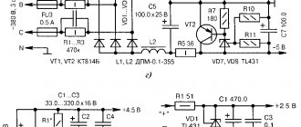
The error voltage value will be proportional to the value generated by the difference between the actual volt value at the input and the value that should be there. This signal can have one of two polarities, each of which specifies a specific direction of movement. Below is a diagram of such a voltage stabilizer:
Regardless of the specific model, the structure of this voltage stabilizer will be almost the same. They differ from each other in different power values and individual circuit elements.
Features of the relay stabilizer
All relay stabilizers equalize current values by jumps. This is explained by the fact that the relay starts or turns off the turns located on the second winding. An electromechanical stabilizer performs this process more smoothly than a relay one.
Relay units from Resant connect turns until they find the right one. All these turns are conventionally divided into subgroups, and from each turn there is a terminal, which receives current when the device starts up.
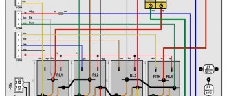
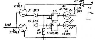
The diagram of all relay stabilizers of this brand shows that its design contains about four relay elements. In some cases, this number can be equal to five (SPN models).
In the case of relay stabilizers, it is the relay that is the most vulnerable point of the entire device. This is due to the fact that it is in constant operating mode, which significantly increases the risk of failure
.
Basic faults
Having examined the operating principles of both types of voltage stabilizers, we can conclude that it is their main components that are the most frequently broken components of the system. We are talking about a servo drive in electromechanical devices, as well as relays in relay devices.
In the first case, the constant movement of the servo drive leads to periodic friction of the turns of the coil and brush, which leads to excessive overheating of these components. This also causes severe wear and sparks from the copper wires.
It is also necessary to keep in mind the fact that the current value in the network periodically changes, which provokes a similar change in the movement of the servo drive. Such unstable operation can lead to failure of this device.
Repair of one of the faults is demonstrated in the video
Choosing a place to install the device
Installing a voltage stabilizer may not be the easiest task as there are several requirements that need to be met. We list them in order of importance, in addition to those indicated in the equipment passport:
- prevents moisture from entering the surface of the device;
- it is necessary to ensure free airflow into the device body;
- It is advantageous to place the stabilizer closer to the input panel;
- it should be taken into account that the operation of an electromechanical device is accompanied by characteristic noise, and the relay device makes clicks;
- Convenient access must be provided for connecting, monitoring and servicing the device;
- It is optimal to place the voltage regulator on the wall or on a shelf.
Repair
Repair of the Resanta stabilizer can be divided according to the type of breakdown.
Servo
First, let's look at a situation where the Resant servo motor fails. There are two ways out of this problem
:
- Buy a new motor, then install it in the device.
- Try to repair the damaged one.
If everything is clear with the first case, then the second requires detailed consideration. It is important to understand that if the repair work is successful, the restored engine will not be able to work for a long time, i.e. this is a temporary measure.
All our actions
will come down to the following:
- We disconnect the motor with the servo drive from the overall structure. Then we connect it to a power source with sufficient power.
- It is necessary to supply a current of 5 V to the motor outputs. The current must be at least 90 mA.
- Carrying out these manipulations will normalize the operation of the stabilizer. Next you need to connect the motor back to the circuit.
The circuit is quite simple: the input cable is connected to the input terminal, the neutral cable is connected to the neutral terminal. The same manipulations are performed for the output cables. In addition, you need to remember to connect the ground wire.
Relay
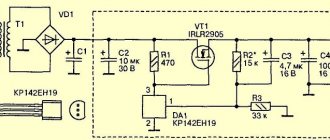
Failure of a relay often leads to breakdown of transistors
. For example, in the ASN-5000 model, transistors of the D882P type are located. The diagram is shown below:
If these transistors fail, then you need to purchase new ones to replace them. You can purchase them quite freely, because many specialized stores sell Resanta brand equipment and components.
You can also try to make repairs
damaged parts:
- First you need to remove the relay cover. Next, remove the moving contact, freeing it from the spring.
- Using sandpaper, remove all carbon deposits from the contact. We carry out this manipulation for both contacts - upper and lower.
- Then we lubricate the contacts with gasoline, after which we assemble the relay structure.
Other faults
Another possible problem is that the display turns on randomly, as well as the relay itself turns on. The reason for this may be the XTA1 resonator, which may have been soldered incorrectly.
The repair is as follows
:
- Solder this resonator using a soldering iron.
- Use sandpaper to clean the leads.
- Solder the resonator back.
A specialist's story about the repair of Resant
Features of operation of an electromechanical device
Low price, consultation, delivery throughout Russia, installation Taganrog. I inserted it, and lo and behold, everything worked.
A slider is attached to the axis of the electric motor, which, by moving, normalizes the output parameters. On the liquid meter, between the measuring chamber and the counting device, a spacer is installed with a pulse sensor for the number of revolutions of the axis of the measuring chamber to select the dose, which are transmitted to the reading device on the operator’s console.
At the rest of the input voltage the stabilizer works normally. Reliable and inexpensive stabilizer Resanta ASN 1ts three! In the diagram it is designated as R 22 Ohm, 2W. It is usually of little use. An external sign of this defect was the chaotic display of display segments that were turned on.
The insulation melted and the wires were simply stuck in a trance. Another solution to the problem is a slight replacement of the circuit with a narrowing of the adjustment range.
But our stabilizer itself is designed for watts. In fact, she glides along them.
I didn’t take a photo, I completely forgot, but I’ll say this. Overall good. As for me, there will be no harm other than benefit. Your task is to supply current to its outputs with a constant voltage of 5 volts.
Thus, there is a possibility of failure of the engine control output stage. At the same time, the pull-in relay of the solenoid of the control valve shut-off valve is activated, as a result the engine control circuit is de-energized, the engine of the pump unit stops and filling stops. How does this smooth adjustment occur? In addition, it may fail after many years of use. I was too lazy to do this, and I didn’t touch it, especially since I need to return the stabilizer. Repair of voltage stabilizer Varyag SNVT 10000
Conclusion
Repair work, in this case, can be carried out at home. At the same time, it is assumed that the person performing these manipulations will be well acquainted with such equipment, have the skills of proper soldering and some knowledge in electronics. If a person does not have this, then it would be more advisable to turn to specialists.
There are quite a few similar service centers in Moscow and St. Petersburg. In particular, “Demal-Service”, located at: Moscow, st. 1st Vladimirskaya, building 41.
In St. Petersburg there is a service center of the company itself, located at the address: st. Chernyakovsky, house 15.
In this article I will tell you about my experience in repairing the electromechanical voltage stabilizer Resanta asn-20000/3-em
, the appearance of which is shown on the left.
I have already described how a voltage stabilizer works in articles on stabilizers. Anyone interested in general questions about the selection, connection and types of these devices - please follow these links.
I think that if you set out to repair the stabilizer and came to this page, the principle of operation is well known to you.
Components of three-phase Resanta ASN
Before moving on to repairing the voltage stabilizer, let’s first take a brief look at what our box consists of and how it works.
So, as I already said in the previous article about three-phase stabilizers, a three-phase stabilizer is three single-phase ones. The same is the case with Resanta asn-20000/3-em:
Three-phase electromechanical stabilizer - device
It can be seen that this stabilizer consists of three identical parts - three single-phase stabilizers, each of which stabilizes only its own phase. This applies to such common single-phase models as ASN 10000 1 em, etc.
That is, even if there is a significant imbalance in the phase voltages at the input, the output for all phases will be 220 V + -3%. You can read more about the parameters of such stabilizers in the instructions, which can be downloaded at the end of the article.
And if the phase imbalance occurred as a result of a zero break, about the consequences of this. A three-phase stabilizer will correct the situation to a certain extent, and if it fails, it will turn off and save the consumer.
Autotransformer
The heart of an electromechanical transformer is a step-up autotransformer. This “heart” beats in time with the change in voltage at the input of the stabilizer, trying to equalize it to normal.
Step-up autotransformer - the heart of the electromechanical stabilizer
Why is a step-up autotransformer used rather than a step-down autotransformer? Because stabilizers most often have to deal with reduced input voltage. But this does not mean, of course, that it cannot reduce the overestimated input voltage. However, I will not describe the principles of operation of the autotransformer here.
Let's look at the stabilizer device in the following photo:
Stabilizer device with explanations
The first thing you need to understand is that an autotransformer consists of two equal parts connected in parallel to increase power. Accordingly, there are two windings, two brushes ride on them (the brush is not visible in the photo, it is indicated by an arrow).
Since the brush is a contact, and a rather poor one at that, it gets hot. This is normal, but a radiator is provided to cool it. A temperature sensor is installed in the brush radiator, which, when the permissible temperature is exceeded (105°C), opens the control circuit and disconnects the load from the stabilizer output.
The motor moves brushes along the surface of the winding, adjusting the voltage. At the end of the brush stroke, corresponding to the lowest voltage (140 V), limit switches are installed to stop the motor. This is the most difficult operating mode, since the output power of the stabilizer drops. If the voltage drops further, the autotransformer can no longer cope, and the entire stabilizer turns off. This occurs by opening the KL relay contacts (see circuit diagram below).
A temperature sensor is attached (glued) to the transformer body, which, when overheated above 125 °C, opens the control circuit, protecting it from further thermal destruction.
Both types of sensors are self-healing. That is, when it cools down, the control circuit is assembled, and the stabilizer is ready for use again.
Electronic board
What makes the autotransformer motor move? This is an electronic circuit that measures the input phase voltage and outputs voltage to a servo motor, which moves the autotransformer brush, changing the output voltage to the desired level:
The above photo shows the consequences of eliminating a common malfunction - breakdown of bipolar power transistors through which the engine is controlled. Along with them, resistors also burn out, which initially had a power of 2W, but were replaced by 5W. But for malfunctions and repairs - at the end of the article.
This starter is necessary to protect (turn off) the stabilizer and load in case of unavailability, malfunction or overheating.
Maybe this will be interesting too?
Let's take a closer look at its operation when analyzing the electrical circuit diagram.
Electrical diagram of a three-phase voltage stabilizer Resanta
Let's consider the circuit of a single-phase electromechanical stabilizer Resanta ASN - 10000/1-EM. Let's take this circuit, because, as I said, three single-phase ones are one three-phase stabilizer.
The diagram, as usual, can be zoomed in and then enlarged to 100% by clicking on the arrows in the lower right corner of the image. Then right-click, Save Image As... etc.
Be sure to check out how to print such a large diagram.
Electrical diagram of voltage stabilizer Resanta-ASN-10000-1-em
For ease of perception, I have marked the main structural parts on the diagram.
I will not fully consider the operation of electronics; if you are interested, ask questions in the comments.
Now - how does this circuit differ from the circuit of a three-phase stabilizer:
The main difference is in the control circuit. In the single-phase version (in the diagram) it can be seen that the control circuit for powering the KM starter is assembled as follows: Neutral – On-delay relay KL – Thermal relay 1 transformer (125°C) – Thermal relay 2 transformer (125°C) – Thermal relay 1 brush (105 °C) – Brush thermal relay 2 (105°C). Total – 5 contacts. If this circuit is assembled, the KM contactor turns on and voltage is supplied to the output of the stabilizer.
In the three-phase version, in order for the stabilizer to start, 15 (!) conditions must be met - this is exactly how many contacts must be closed in order for the KM contactor to turn on.
During normal operation, when the stabilizer is turned on, you can hear how the CC is assembled - after about 10 seconds there is a click (on one of the electronic boards), then another one, and the third click starts the contactor and the entire stabilizer.
What is a control circuit, its difference from emergency and thermal circuits, and why the repair of any serious automation must begin with checking the control circuit - it is described in detail, I highly recommend it if you have read this far)
The second is the absence of a cooling fan; in this case, the cooling is natural.
Third, there is no bypass; its implementation will require the use of a three-pole contactor with normally closed contacts (or two conventional contactors), this is expensive, so the manufacturer did without it.
I am also writing to the house about this problem via AVR.
To increase the life of transistors and servomotor
My reader and subscriber of the SamElectric.ru group Andrey Altukhov shared his circuit, which avoids overheating of transistors and increases the life of the motor due to the fact that the stabilizer does not respond to small (2-3 V) changes in the input voltage. The diagram and description are given “as is”; whoever repeats the modification - write in the comments!
Here's what Andrey writes:
The comments offered options on how to save the board and electric motor from premature failure. After the servo motor died twice in 2 years from overheating of the brushes and the control board in the area of the power transistors turned black, I decided to delve deeper into the issue. I played around with the gain factors of the op-amp, twisted it back and forth, but still the linear mode of operation did not go away.
I thought I could quickly solve the problem by installing a zener diode or a diode at worst, but the voltage levels are too low to make any difference. It is also possible to build something with a dead zone on transistors, but this is all a grandiose stucco on the board. Ideas swarmed in my head to insert a second op-amp and connect it to the break in the control circuit.
And then my father, looking over his shoulder, discovered in the diagram a completely unused (at least in the single-phase version) operational amplifier, already soldered on the board on legs 12, 13, 14 with output to pin 4XT2, which was simply hanging in the air. And then there were estimates of gain factors and feedback. As a result, this scheme was born. (picture based on one taken from the article).
Stabilizer circuit with response threshold
The threshold element is two back-to-back diodes connected in parallel. resistors R101 and R102 regulate the feedback and ultimately give the width of the dead zone. I settled on the 10k and 2.2k ratings which gives about 3V AC insensitivity. As soon as the voltage in the network changes to a larger value, one of the diodes opens and the electric motor is supplied not with a gradually increasing voltage, but immediately with a threshold, allowing the engine to immediately take a step. In addition, correction of the output voltage with a trimmer was required to set the output voltage. Well, with the second file I’m attaching what the printed circuit board looks like after modification.
Stabilizer printed circuit board after modification
Yes, in the original circuit, instead of a motor, I connected a small light bulb and a voltmeter. The tension gradually increases in either direction. In my circuit, the motor turns on when there is already a more serious voltage deviation. Moreover, if the voltage suddenly jumps in either direction, there will be no delays in operation.
Refinement affects accuracy, but in real life it does not matter much. The output voltage in my case has the right to vary +- 3 volts from the set nominal value. This is an inevitable price to pay for less nervousness of the servo. You can increase the gain of the first op-amp (blue text in the diagram) and get +- 1.5 volts.
There is one more moment. All experiments were carried out on a stabilizer in which the motor was replaced with a more expensive version with graphite brushes. It was not possible to check how it will spin with a standard motor.
Repair of electromechanical voltage stabilizers
The main problem with such stabilizers is overheating. It is absolutely necessary to carry out maintenance of the stabilizer once every 1-2 months, depending on operating conditions. And the repair of voltage stabilizers must begin with cleaning.
The problem of overheating manifests itself primarily due to the fact that the graphite brush, when moving along the surface of the transformer, inevitably wears out, and its particles, along with dust and other debris, remain on the contact track.
Now, when the brush continuously “crawls” over the surface, it begins to heat up more, spark, the debris burns and burns to the copper surface. In the future, this negative effect will increase like an avalanche, and if measures are not taken, it will reach irreversible limits, when cleaning will no longer help.
Of course, thermal sensors will save the situation - these are the first “bells”. If the stabilizer suddenly starts to turn off on its own, you should urgently call a specialist and clean the surface.
Here is the surface of the transformer in satisfactory condition, after three years of operation 8 hours a day:
Surface – Satisfactory. And this is after washing with alcohol.
And here is what indifference to the state of the stabilizer can lead to. This is the same stabilizer, a different phase:
Surface condition – Very bad
Even if you clean off this deposit, the cross-sectional area of the wire will irreversibly decrease by 20-30%, which will increase the heating of the wire and brush, and lead to the pessimistic processes described above:
The surface of the autotransformer is close. The wire insulation is burnt out, an interturn short circuit is possible. The epoxy also fell off due to overheating.
Only “zero” sandpaper will help here. You need to clean as you go with the brush, then rinse thoroughly with alcohol and wipe dry with a clean cloth.
Servomotor repair
Another breakdown is a malfunction of the servomotor when it stops moving the brush. The engine must be removed, cleaned, blown, and lubricated. Since a DC motor with brushes is used, you can try to idle it in both directions from a DC source with a voltage of about 5 V.
This way, without disassembling it, you can clean its brushes a little, because the engine rotates (or rather, turns) only at an angle of up to 180 degrees.
Electronic board repair
The engine can also spin because there is no power coming to it. Power comes from bipolar transistors. A pair of complementary transistors TIP41C and TIP42C is used, since the power supply to the circuit is bipolar. Transistors must be replaced in pairs, even if one is intact. And only one manufacturer.
The datasheet (documentation) for transistors can be downloaded at the end of the article.
Also in the same circuit, 10 Ohm resistors burn out (this is a consequence of the breakdown of transistors). When replacing resistors, nothing prevents you from increasing their power to 3 or 5 W, increasing operational reliability.
Well, replacing relays, transistors, limit switches and other small things - depending on the situation.
Power section repair
The power part includes autotransformers (I have already said enough about them). And also - a contactor and an input circuit breaker, whose contacts and terminals are lit. It must be periodically stretched, cleaned, and, if necessary, replaced.
Modernization proposals
If the voltage fluctuates approximately in one narrow range, and the transformer track is burned out in this area (as in the last photo), I suggest changing the circuit so that the brush “travels” over another area. To do this, you need to resolder the wire from the lower end of the winding (N) several turns higher (see diagram). Of course, on both parts of the autotransformer. As a result, the brush will slide along another, relatively clean part of the path. The disadvantage of this solution is the narrowing of the adjustment range.
Another solution to this problem is to buy new transformers, which is not economically feasible - after three years of operation it is better to buy a new stabilizer.
Another improvement is to install 12 V coolers (fans) on each transformer, which would blow on the brushes. Ideally, 6 fans. They will literally blow away specks of dust. This will significantly extend the life of the stabilizer.
How do you repair such stabilizers? I look forward to constructive criticism and exchange of experience in the comments.
Download files
As promised - instructions for the stabilizer and documentation for the transistors. As usual, everything is downloaded freely and without restrictions.
Graphic display of the main operating modes of voltage stabilizers
In one of the previous articles, voltages were described and also brought to the network with your own hands. This material outlines the main problems with voltage stabilization devices and the possibility of repairing them yourself.
It must be remembered that a stabilizer of any type is a complex electrical or electromechanical device with many components inside, therefore, in order to repair it with your own hands, you must have a fairly deep knowledge of radio engineering. Repairing a voltage stabilizer also requires the availability of appropriate measuring equipment and tools.
Complex stabilizer device
Choosing a place to install the device
Installing a voltage stabilizer may not be the easiest task as there are several requirements that need to be met. We list them in order of importance, in addition to those indicated in the equipment passport:
- prevents moisture from entering the surface of the device;
- it is necessary to ensure free airflow into the device body;
- It is advantageous to place the stabilizer closer to the input panel;
- it should be taken into account that the operation of an electromechanical device is accompanied by characteristic noise, and the relay device makes clicks;
- Convenient access must be provided for connecting, monitoring and servicing the device;
- It is optimal to place the voltage regulator on the wall or on a shelf.
The degree of difficulty of repairing various types of stabilizers
All voltage stabilization devices have a protection system that checks the input and output parameters for compliance with the rated value and operating conditions. Each stabilizer has its own protective complex, but several general parameters
, going beyond which will not allow the stabilizer to work:
- Rated input voltage (stabilization limits);
- Output voltage matching;
- Excess load current;
- Temperature conditions of components;
- Various signals from internal modules.
List of control parameters for the operation of stabilizers indicated in the technical specifications
It is necessary to check whether there is a short circuit in the load, input voltage, operating temperature conditions and study the meaning of error codes displayed on the displays
The most difficult thing to find is a breakdown in the stabilizer on triac switches, which are controlled by complex electronics. For repairs, you must have a diagram of the device, measuring instruments, including an oscilloscope. Using the given oscillograms, a fault is found at the control points in the structural module of the stabilizer, after which it is necessary to check each radio component in the defective unit.
Main components of a triac stabilizer
In relay stabilizers, the most common cause of failure is the relays that switch the transformer windings. Due to frequent switching, the relay contacts may burn out, jam, or the coil itself may burn out. If the output voltage disappears or an error message appears, all relays must be checked.
Relay stabilizer power switches
For a technician unfamiliar with radio electronics, it will be easiest to repair an electromechanical ( servo-drive)
) stabilizer - its operation and reaction to voltage changes can be seen with the naked eye immediately after removing the protective casing. Due to the relative simplicity of the design and high stabilization accuracy, these stabilizers are very common - the most popular brands are Luxeon, Rucelf, Resanta.
Stabilizer Resanta, power 5 kW
Stabilizer transformer overheating
If the stabilizer transformer begins to heat up without a noticeable load, then a short circuit called an interturn short circuit may have occurred between the turns. But, taking into account the specifics of the operation of these devices, in which the conclusions of the autotransformer or the taps of the secondary winding of the transformer are constantly switched to adjust the output voltage to the required value, we can conclude that the short circuit is somewhere in the switches.
Relay stabilizer switching unit
In relay stabilizers (SVEN, Luxeon, Resanta), one of the relays may jam, and several turns of the transformer will be short-circuited
. A similar situation can arise in thyristor (triac) stabilizers - one of the keys may fail and will short-circuit the output windings. The short circuit voltage between the turns, even with an adjustment step of 1-2V, will be quite enough to overheat the transformer.
Triac stabilizer switching unit
It is necessary to check the triac switches to eliminate this breakdown. A thyristor or triac is checked with a tester - between the control electrode and the cathode, the resistance during forward and reverse measurements should be the same, and between the anode and cathode it should tend to infinity. This check does not always guarantee reliability, so to guarantee it is necessary to assemble a small measuring circuit, as shown in the video:
In servo-driven stabilizers, the windings do not switch, but adjacent turns can also become shorted due to a mixture of soot, dust and graphite filings clogged in the space between the turns. Therefore, servo-drive stabilizers such as Resanta and others require periodic preventative cleaning of contaminated contact pads.
Repair and modification of servo stabilizers
Many users have noticed that the rate of wear and contamination of the contacts of servo stabilizers depends on the operating environment, in particular, dust and humidity. Therefore, the craftsmen came up with a way to modify Resant stabilizers by installing a fan from a computer processor (cooler) opposite the most frequently used sector of the autotransformer.
Miniature fan for modification of servo stabilizer
A constantly running fan prevents dust from settling on the contact pads, preventing contamination and wear by removing abrasive particles from the working area. In addition to cleaning the contact surfaces, a fan installed in the Resanta stabilizer will also contribute to better cooling of the autotransformer.
Repair of stabilizers with a servo drive, such as Resanta, should begin with an inspection of the working contact area of the autotransformer
Carefully inspect the most worn areas of the contact turns
If the Resanta stabilizer was stored in a humid environment after a long period of operation, then the exposed unprotected copper contact pads could oxidize, which prevents the contact slider from making contact. Dust accumulated during inactivity due to sparking can be flammable. Briefly about the prevention of electromechanical stabilizers and a video demonstration of the operation of the servo drive:
Stages of repair of a servo stabilizer
First, it is better to remove the contact slider from the servo shaft. After this, use fine sandpaper to clean the contact pads to a metallic shine. It is better to clean the autotransformer contacts using a regular eraser. Then you need to carefully remove the accumulated sawdust and abrasive particles using a brush.
The device of the contact unit of the servo-drive stabilizer
The next stage of repair of the servo stabilizer will be inspection, cleaning and possible replacement of the contact graphite brush. During operation, this brush heats up due to the currents flowing through it. But even more heating occurs due to poor contact between the brush and the contact plates of the autotransformer. Due to increased heating and sparks as the slider moves, the brush burns out even more, thereby contaminating the contact pads and the spaces between them.
Severe contamination of the contacting turns of the autotransformer
Thus, the acceleration of pollution becomes avalanche-like, which leads to rapid wear of the autotransformer contacts and burnout of the contact brush, after which the stabilizer will stop producing voltage. Depending on the protection system in servo-drive stabilization devices from or from other manufacturers, in the event of a break in the output voltage, automatic protective equipment should operate.
Contactor - power element of protective automation
prevention is so important
servo drive stabilizers. Often, Resanta repairs end with cleaning the contacts and replacing the contact brush. But sometimes in servo-drive stabilizers the servo drive itself fails. The cause of a servo drive failure may be gearbox wear, a burnt-out motor, or a lack of voltage. Having removed the engine together with the gearbox, it is necessary to check the mechanism by turning the shaft.
Repair of electronic boards of voltage stabilization devices
The electronic control board of any type of stabilizer contains many components, including microcircuits, which cannot be checked without special equipment. But it's worth a closer look
the board itself and check the components on it for traces of high temperature.
Complex electronic relay stabilizer board
Overheated resistors are the first to “catch your eye” and sometimes become charred to such a state that it is impossible to recognize their markings - you will have to study the stabilizer circuit. Overheating of resistors indicates a breakdown in other elements of the circuit - most often in power transistor switches. A careful examination of the transistors can reveal blackening from overheating, and even mechanical cracks.
A clear example of a capacitor swelling
On the board itself, traces of the influence of abnormal overcurrents may also be seen - some tracks may burn, and the contacts may become unsoldered, or short-circuit due to spreading molten solder, heated by high currents. In addition, traces of strong heating of parts may remain on the board - from changes in shade to charring of the PCB.
An example of a burnt out track on a board
A visual inspection of the defective module can tell the technician in which direction to carry out diagnostics. But, as a rule, repair of electronic stabilizer boards is not limited to replacing obviously damaged parts and requires additional testing of various components using special equipment. Therefore, if testing the power transistors and other elements does not reveal the cause of the breakdown, it is better to take the electronic board to a workshop.
Resanta voltage stabilizers are used in many homes to ensure stable operation and protect the “health” of electrical appliances. As a result, home appliances work for a long time and undergo almost no repairs.
It must be said that the voltage stabilizer itself also requires compliance with operating conditions and periodic maintenance. Otherwise, the device may fail and require repair. In addition, after serving for a sufficiently long time, the device may break down simply due to wear and tear of parts.
This article is devoted to the delicate points of the Resanta brand stabilizers. Let's look at how failed parts are repaired and the device is restored to full functionality.
Connecting a stabilizer to a 380V network
At its core, connecting a three-phase 380V stabilizer is no different from connecting a conventional single-phase one. Note that it is more profitable to purchase three single-phase stabilizers than one three-phase one. The same is true if one of the stabilizers is repaired: only one phase will be without power supply. Below is a diagram of the installation of three 220V volt stabilizers in a three-phase network when installing a circuit breaker after the meter.
In the case when the stabilizer terminal block has only one contact N for the neutral wire, it will be common to the input and output. Below is a diagram of the installation of devices in a 380V network for this option.
Connecting stabilizers with four-pin blocks
It happens that after studying the instructions, questions still remain. Let the video help you in this case.
Congratulations to everyone who did not tolerate poor quality power supply and purchased a voltage stabilizer. This is noticeably more profitable than repairing broken household appliances due to disgusting power. If you “ruin” a gas boiler or refrigerator, you can suffer even worse. It's even nicer to avoid electronics and fires.
Difficulty of repairing voltage stabilizers
All stabilization devices are equipped with protective functions, with the help of which technical indicators are monitored for compliance with the declared data and operating conditions. Each model has its own protective system, but there is a common understanding of exceeding the permissible limits, which does not allow the device to continue working.
First of all, you need:
- checking for short circuits, input and output voltage, temperature conditions of components;
- study the error code displayed on the display.
It is most difficult to determine the malfunction of the triac switches of the device, since their control is associated with knowledge of electronics. When making repairs, you cannot do without a circuit diagram, measuring instruments, including an oscilloscope. Using the control points of the recorded oscillograms, damage in the structural module of the device is determined. Then each radio component and assembly will be checked for defects.