Surely many of us have wondered why circuit breakers so quickly replaced outdated fuses from electrical circuits? The activity of their implementation is justified by a number of very convincing arguments, including the opportunity to buy this type of protection, which ideally matches the time-current data of specific types of electrical equipment.
Do you doubt which machine you need and don’t know how to choose it correctly? We will help you find the right solution - the article discusses the classification of these devices. As well as important characteristics that you should pay close attention to when choosing a circuit breaker.
To make it easier for you to understand the machines, the article’s material is supplemented with visual photos and useful video recommendations from experts.
Characteristics of circuit breaker releases
For those who prefer to check everything from primary sources, from the text and at the end of the article, I provide GOST standards, which provide clear official definitions.
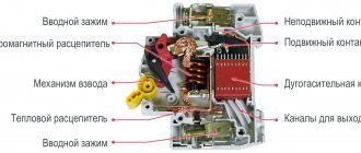
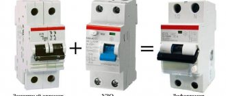
So, inside the machine there are two tripping (switching off) devices, each of which operates independently, in its own current range. The operation of both of these releases leads to the fact that they somehow turn off the circuit breaker when an overcurrent (more than the rated current) flows through it.
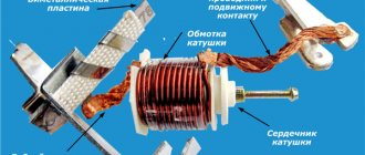
The first is a thermal release , which works on the principle of heating and bending a bimetallic plate through which the operating current of the machine flows. For example, the temperature regulator in an iron and an electric heater operates on the same principle. The plate is calibrated and configured in such a way that at a certain current it heats up to a certain temperature, which leads to its critical bending and, as a result, the machine turns off. The thermal release has some inertia, which has a beneficial effect on its operation in real conditions. So to speak, it “wait” before it works.
The second release is electromagnetic . Its operating speed is much higher compared to a thermal release. The principle of operation is clear from the name - there is an electromagnet that is triggered and turns off the load in the event of a short circuit. The “trip” current of the electromagnetic release is several times (in different cases from 3 to 20) higher than the current of the thermal release.
You can also select an independent release , which closes or opens the contacts of the circuit breaker when operated manually. The name is a bit of a misnomer as it is controlled by a human hand, either a thermal release, an electromagnetic release or an external release.
Let us consider in detail the characteristics of releases with examples and references to GOST.
All characteristics are determined at a control temperature of +30 °C.
Time-current characteristic (VTC)
This is the main characteristic that describes the operation of the circuit breaker. It also has other names -
- response characteristic,
- release characteristics,
- current characteristic,
- disconnecting characteristic,
- protective characteristic,
- current curve,
- shutdown curve,
- tripping characteristic…
The official name from GOST R 50345-2010 (clause 4.5, clause 5.3.5) is the current type (current range) of instantaneous tripping. This GOST is no longer valid from March 1, 2022. Read to the end.
There is only one meaning - this is a graph that shows the dependence of the switch-off time of the machine on the amount of current passing through it:
Time-current characteristic, also known as circuit breaker shutdown curve, protective characteristic
The graph shows three areas - B, C, D. According to GOST R 50345-2010 (clause 5.3.5), each of them determines its own threshold for the operation of the electromagnetic release:
- B – from 3 to 5 In,
- C – from 5 to 10 In,
- D – from 10 to 20 In,
where In is the rated current of the thermal release. That is, the operation current of the electromagnetic release is normalized through the thermal current.
This current, denoted by a letter, is called the instantaneous tripping current:
GOST R 50345-2010, clause 3.5.17 instantaneous tripping current
(instantaneous tripping current): The minimum value of current that causes the circuit breaker to trip automatically without a deliberate time delay. How long does this moment last?
TEXENERGO circuit breakers – with different protective characteristics and rated currents: B6, B16, C40, C32
The response time tср of the electromagnetic release type B is determined as follows (GOST R 50345-2010, clause 9.10.2):
- tav > 0.1 s for current 3 In,
- tav < 0.1 s for current 5 In or more
Does this mean that with a current of 3In it may not work in a time of ≤ 0.1 s? Yes. In GOST it is written “without tripping”. But for a time greater than 0.1 s, the AV must operate through an electromagnetic or thermal release. True, it is not indicated for what time - 0.2 or 2 s?
In the range of 3...5 AB it will work with some probability, and at 5In and more it will work 100%. It depends on the specific instance. And if it does work, it will do so in less than 0.1 s. The actual values lie in the range of 0.01 - 0.003 s, depending on the current and luck - which part of the sine wave contains the short-circuit moment.
For characteristics of type C, D, the response time tср is determined similarly, within its limits.
Why do the BTX graphs show areas rather than lines? The fact is that, in addition to the natural spread of device parameters, the tripping current depends on the temperature state of the machine. The lower part of the graph refers to the case when the machine was in operation for a long time (hot state), the upper part refers to the machine in a cold (unheated) state.
In another article I write about how a circuit breaker differs from a fuse.
I believe that it is much more convenient to use not graphs with relative values, but tables that indicate characteristic operating points for a machine of a certain denomination. Read the article in which I provided tables with working values of AB of different denominations.
When will thermal protection work, and when will electromagnetic protection work?
To make it clear, for example, let’s take the B10 circuit breaker - protective characteristic B, rated current 10 A - and analyze the current characteristics graph for the main current ranges:
- 0...11.3 A - the machine should not turn off, this is the current range for its normal operation,
- 11.3...14.5 A - there is a possibility that the machine will operate after some time as a result of the action of the thermal release (more details below),
- 14.5...30 A – the shutdown time for thermal protection will be from 1 hour (for a current of 14.5 A) to 4 s (for 30 A),
- a thermal release (in a time of 4 to 1 s) and an electromagnetic one can operate .
- if the overcurrent is more than 50 A (>5 In), only electromagnetic protection works, since the thermal protection is too inertial.
What will change if we take the C10 machine gun as an example? Only the area where both releases operate will change; it will move to values of 50... 100 A. For the D10 machine, this range will be 100... 200 A.
Why is there such a big spread? It comes from the variation in the operating characteristics of real machines. That is, for B10 at a current of 30 A the electromagnetic protection CAN work, but at a current of 50 A it MUST work.
Why do we need different protective characteristics of machines? The only differences are in the thresholds for turning off the electromagnetic release. Exceeding the current several times can occur when starting various inertial devices. This current is called starting current, and it appears in everyday life as a result of turning on electric motors.
For most household devices, the power of the built-in motors is no more than 2.2 kW, this is a rated current of 10 A. In this case, the starting current is up to 50 A for especially difficult starting conditions, and it lasts less than a second. For the C16 machine, switching off based on the starting current can only occur if the current exceeds 80 A.
The current at which the electromagnetic release is triggered can, in practice, also result from a short circuit. But the short circuit current is not infinite - it is determined by the resistance of the circuit from the substation to the point of the fault. If the resistance of the wires and the contact resistance of the contacts is high (and in the private sector this is quite common!), the current during a short circuit somewhere in the carrier can be only 100 A. If the smallest circuit breaker is set to 25 A with type C protective characteristic, electromagnetic protection will work (depending on your luck!) at a current of 125 to 250 A. That is, it will not work at all! A thermal release will help out, but its reaction time can be from 2 to 10 s. And during this time, anything can catch fire from sparks and flames from the ill-fated carrier.
It could be even worse: the instantaneous tripping current of a particular instance of the C25 machine can be equal to 250A. And the short-circuit current can be 249A! The thermal release will operate in about a second, and during this time catastrophic events can occur.
That is why in the private sector, where the substation is several kilometers away from old aluminum, and in apartments, I highly recommend installing machines with characteristic B (article about choosing an AB for a home panel). Here is a more extensive article on this topic on the blog.
Protective characteristic C is quite acceptable and is still used everywhere.
Characteristic D is not used in everyday life and is even harmful - there are not and cannot be large inrush currents exceeding the rated current by 10...20 times. And given that in a private house there is often a very low short-circuit current, the electromagnetic release “D” becomes useless and dangerous - we are deprived of short-circuit protection.
Let us consider in detail several terms and points on the characteristic.
Rated current of thermal release In
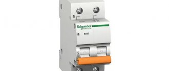
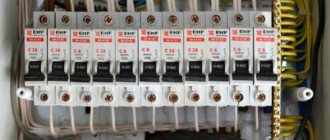
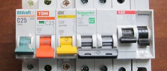
This is the maximum current that the machine can reliably carry for an unlimited time without negative consequences and tripping of the releases. The rated current is indicated by a number on the front of the machine; the type of protective characteristic is indicated before the number.
Rated current In is the main parameter of the circuit breaker.
The example in the photographs above is B6. Another example, machines with a rated current of 40 and 32 A and protective characteristic C:
Circuit breakers TEXENERGO BA47-29 C40, C32
Non-tripping current of thermal release 1.13 In
This is a current whose action does not turn off the machine. It is also called conditional non-trip current . GOST R 50345-2010 (clause 8.6 and clause 9.10) states that the machine should not turn off for an hour at a current of 1.13 In . That's why the characteristic shows a value of 1.13.
Thermal release breaking current 1.45 In
This parameter is also called conditional trip current . It is equal to 1.45 In . In other words, with an overcurrent exceeding the nominal value by 1.45 times, the machine must be guaranteed to operate under thermal protection within an hour of operation.
1.13 In through it for an hour and then immediately, without turning off, increase the current for 5 s to 1.45 In.
Thermal release test current 2.55 In
This point is not marked on the graph, but is given in GOST (R 50345-2010, clause 9.10.1.2). This current is used to check the operation of the thermal release of the circuit breaker. To do this, a current of 2.55 In to all poles of the machine in a cold state. The opening time should be in the range from 1 to 60 s for circuit breakers with In ≤ 32 A, and from 1 to 120 s for In > 32 A.
Conclusions according to the VTX schedule
Reading these rules and looking at the performance characteristics chart, two conclusions can be drawn.
- The rules allow greater variation in shutdown times than indicated in the graph.
- The 2.55 In point was not chosen by chance - at this current in all types of machines, only the thermal release is involved in switching off.
Correction of rated current depending on temperature
There are two factors for temperature correction - the number of nearby circuit breakers and the ambient temperature.
As I said above, all characteristics of the thermal release are determined at an ambient temperature of 30 °C. However, the machine warms up during operation, this is normal. When there are several circuit breakers in the panel (and this always happens), they mutually heat each other, and the thermal release will operate earlier than the nominal value.
I included information on heating circuit breakers in a separate article - what will happen if you heat up a circuit breaker. Changes in machine characteristics depending on temperature.
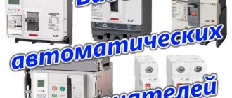
Classification by design
There are three types of network protection circuit breakers:
- Modular device. Relevant for household networks with small currents flowing. Most often it has one or two poles.
- Cast. Used to work in industrial networks. The name was given due to the cast body.
- Air electric. Suitable for networks supporting high-power installations. Usually has three or four poles.
Rated short-circuit breaking capacity, Icn
The trip curve (BTC) graph above only shows overcurrents up to 100 I/In. However, the range of currents usually extends further into the kiloampere region, up to the short circuit current at a given point in the circuit. Of course, with such currents, the task of the machine is not only to disconnect the shorted load, but also to maintain its functionality .
The breaking capacity of the circuit breaker must be much greater than the expected short circuit current in a given circuit.
After all, when the contacts are turned off (opened), an electric arc (actually a flame) occurs, which can lead to a fire, explosion, or burning of the contact surface. And even - fusion and welding of contacts! To reduce the likelihood of such consequences, the arc is extinguished by specially designed arc-extinguishing chambers, and the contacts are made of resistant alloys.
Rated short-circuit breaking capacity 6000 A = 6 kA
According to GOST R50345-2010 (clause 6f), the Icn parameter is indicated in a frame, and in this case it is equal to 6000 A. Some cheap brands have Iсn = 4500 A, and more expensive machines of this size have 10 kA.
As I said above, it is not at all a fact that such a current will flow through the circuit breaker at the time of short circuit, unless the circuit breaker is located next to the substation. However, this parameter indicates the ability to firmly respond to short circuits, eliminating the possibility of fire, without losing any of its qualities.
I came across machines that, after the first short circuit, did not want to turn on at all. However, this is forgivable - this building had its own substation.
The name of the parameter comes from the English words “ C apacity Normal ”. Or “Rated Short-Circuit Capacity (Icn)”. Other common names for this parameter are maximum switching capacity, rated maximum breaking capacity, rated breaking capacity, rated maximum breaking capacity .
often confused with the rated conditional short-circuit current Inc. Despite the fact that this current has the same values (4500, 6000, 10000), it is used in describing the characteristics of differential protection devices (RCDs).
The Icn parameter is also often confused with the two parameters that I will give below. This is due to the fact that for devices with low breaking capacity, all these three parameters have the same numerical value.
VA types (pole and four groups)
The types of circuit breakers can be classified according to several criteria; we will dwell on some of them.
Number of poles: 1p, 2p, 3p and 4p
This characteristic shows how many independent electrical circuits the machine can switch. According to this parameter, VAs are divided into single-pole (designation 1p), two-pole (2p), three-pole (3p) and four-pole (4p).
Each pole is a separate mechanical contact that has two terminals for connecting external electrical circuits. Sometimes the poles are called main circuits, i.e. These are circuits of contacts designed to switch currents of the protected load.
The number of poles (1p, 2p, 3p, 4p) of each switch can be easily determined.
The concept of main poles or circuits was introduced because Some types of machines have up to several auxiliary contacts. These contacts are not intended for switching power electrical loads and are not equipped with arc extinguishing devices. There are also auxiliary contacts (also called block contacts), they work in signaling and blocking circuits.
Time-current characteristic
Depending on the characteristics of the electrical circuit, the circuit breaker must have appropriate protection properties. The value of short circuit currents is a characteristic of the supply network, and not of the connected load. A load of the same rated power and voltage can be connected to powerful substation busbars, or to a long power line, at a great distance from the power source. StabExpert.ru reminds that in the first case, the short circuit current will have a maximum value, in the second, due to the influence of the resistance of the power line, it can be significantly reduced. Thus, when choosing a suitable circuit breaker, it is not enough to take into account only the load characteristics; you need to have calculated values of short circuit currents at the intended installation location.
Ultimate Icu and operating Ics breaking capacity
The values of the rated short-circuit breaking capacity Icn are equal to 3000, 4500, 6000 and 10000 A (clause 5.3.4), and at the same time equal to the values of the maximum breaking capacity Icu (clause 5.2.4).
It’s a little unclear to me here - if these parameters are equal, why does Icu exist? If anyone knows, please share in the comments!
It is not yet clear (perhaps this is a translation error) why instead of the rated maximum breaking capacity in the specified GOST they write “rated maximum switching capacity”. I hope it's the same thing.
The current Icu for the machine is extreme, limiting ( U ltimate), but the manufacturer guarantees that the machine will safely turn off the emergency circuit, even at the cost of its own life.
The values of the rated operating breaking capacity Ics are calculated based on the rated short-circuit breaking capacity Icn:
Ics = %Icn
Operating and rated breaking capacity. Ratios for different values
The word “working” ( Servise ) means that the machine can be turned on after a given short-circuit current (of course, after eliminating the causes of the short-circuit), and it will continue to work with the same parameters. current Ics three times during the entire period of operation (but this is not certain), then it must be replaced. You can read more in GOST.
The parameters Icu and Ics are not used in domestic use, and as a first approximation ( Icn ≤ 6 kA) we can say that Icn = Icu = Ics , and for household electrical panels it is quite sufficient to use an AB with a breaking capacity of 4.5 kA.
However, if we talk about incoming circuit breakers, according to GOST 32397-2013, at currents up to 63 A, the rated maximum breaking capacity must be at least 6 kA, and at currents up to 125 A - at least 10 kA.
In English terminology, where it all came from, it sounds like Rated Ultimate Short-Circuit Breaking Capacity (Icu) and Rated Service Short-Circuit Breaking Capacity (Ics)
I write more about power machines in a molded case, for which these parameters are important, in another article.
High current categories:
1) over short circuit currents, when the neutral and phase conductors are directly connected to each other, bypassing the load.
Modern electromagnetic releases easily and completely accurately detect short circuits and disconnect the load in a fraction of a second, preventing even the slightest damage to conductors and equipment.
2) large currents caused by network overload (for example, the inclusion of a large number of household electrical appliances, or the malfunction of some of them);
The overload current is not much different from the rated current; for some time it can flow through the circuit without any consequences. Therefore, there is no need to turn off such current instantly, especially since it could arise very briefly. The situation is aggravated by the fact that each network has its own overload current limit. And not even alone.
Current limiting class
This parameter indicates the speed of the machine. The parameter value is given in the box below the Icn value:
The current limiting class of the machine indicates the speed of electromagnetic protection
The number in the frame indicates the part of the voltage period during which the electromagnetic protection will operate in the event of a short circuit. If the number “3” is indicated, it means that during a short circuit the machine will have time to work in 1/3 of the period, or in about 6 ms.
However, nowadays technology has advanced so much that all manufacturers easily fulfill this condition, and a circuit breaker of any brand has current limiting class 3.
Circuit breaker device
A circuit breaker (in the language of electricians, “automatic”) is the basis of protection in low-voltage (up to 1000 Volt) power electrical circuits. This is a combined electrical device that combines the functions of a switch and a protective device. Almost the entire distribution and protection system for household electrical wiring is built on automatic devices. I would like to immediately note that the main use of the machine is to protect that section of electrical wiring that is located between the outlet of the machine and the consumer. If there is another machine further along the line, then our machine must defend the area between these two machines. If an overload or short circuit occurs in any section of the circuit, only one circuit breaker should operate, protecting that particular section of the circuit.
Download
For those who are interested in the topic deeper and more thoroughly, I am posting GOST, which describes in detail all the characteristics and terminology regarding circuit breakers.
At the moment, GOST R 50345-99 (IEC 60898-95) (Small electrical equipment. Circuit breakers for protection against overcurrents for household and similar purposes) is not valid, instead GOST R 50345-2010 (IEC 60898-1:2003) has been introduced ( Small-sized electrical equipment. Circuit breakers for overcurrent protection for household and similar purposes. Part 1. Circuit breakers for alternating current). I am posting it for download:
• GOST R 50345-2010 / GOST R 50345-2010 (IEC 60898-1:2003) Small-sized electrical equipment. Automatic switches for overcurrent protection for household and similar purposes. Part 1. Circuit breakers for alternating current. This standard applies to air circuit breakers (hereinafter referred to as circuit breakers) for alternating current for operation at a frequency of 50 or 60 Hz with a rated voltage (between phases) of not more than 440 V, a rated current of not more than 125 A and a rated breaking capacity of not more than 25,000 A. , pdf, 1.89 MB, downloaded: 1057 times./
• Kharechko V.N., Kharechko Yu.V. Automatic switches of modular design / Kharechko V.N., Kharechko Yu.V. Automatic circuit breakers of modular design: Reference manual. The reference manual sets out the requirements of GOST R 50345-99 (IEC 60898-95) for household circuit breakers intended for overcurrent protection, examines the design of circuit breakers, gives characteristics and their classification. Errors are analyzed that are partially corrected in the new version of GOST R 50345-2010, pdf, 7.17 MB, downloaded: 1062 times./
Update according to GOST for circuit breakers dated March 1, 2021.
GOST R 50345-2010 (IEC 60898-1:2003) is no longer valid; instead, GOST IEC 60898-1-2020 with the same name has come into force. In addition, there is GOST IEC 60898-2-2011 , which more accurately shows the control points of the performance characteristics in table 7 and clause 9.
An article about short-circuit current, published in the paper magazine “Electrical Technical Market”:
• Short-circuit current: size matters / Article about short-circuit current, published in the magazine Elek.ru, pdf, 4.45 MB, downloaded: 604 times./
That’s all for today, I’m waiting questions and fair criticism in the comments.
And in the second part of the article we will look at the design of the circuit breaker from the outside and inside, and also test it.
Connecting overcurrent protection
The diagrams are diagrams, but in the end you need to take a screwdriver and connect the wires to the electrical panel. Let's start by removing the insulation from the end of the wire. The insulation removed must be of sufficient length. Too short insulation means, firstly, a smaller contact surface of the switch with the cable, and secondly, the risk of screwing the fastener onto the insulation instead of the bare wire. Correct tip length: 10-15 mm.
Secondly, you need to insert the wire where it should be. The cable must be between the movable clamp and the top of the hole. The problem, despite its simplicity, can be real. Most often they look at the switch from the front, so they cannot see the terminals and it is easy to make a mistake.
The terminals on both sides of the switch function the same. Connecting two wires to a circuit breaker is possible provided that both wires have the same cross-section. Trying to connect wires with different cross sections is not recommended.
A thinner wire may jump out of the mount during operation. In the above pictures there are two wires connected: brown 2.5mm2 and black 1.5mm2.