Electrician in the house
Encyclopedia about electricity from A to Z
Masters catalog
Find the best master or company in your city
Current electromechanical relay
What is a current relay? This question often arises among students and self-taught electricians. The answer to it is quite simple, but in textbooks and many articles on the Internet it contains a huge number of formulas and references to various laws. In our article we will try to explain what it is and how it works literally on your fingers.
- Current relay device
- Purpose and methods of connecting a current relay Purpose of a current relay
- Current relay connection diagrams
According to the method of operation, current relays are divided
- direct action - affecting the switching off of the circuit breaker;
- indirect - with their contacts they close the circuit of the shutdown electromagnet, which receives power from the battery.
To facilitate the design, indirect-acting relays are manufactured for rated currents up to 10A. Since these devices perform, in principle, insignificant work, they can be made quite sensitive and accurate. In addition, current relays are easily integrated into secondary circuits, which is why they are widely used in relay protection systems. The disadvantages of this type of current relay include the need for an operating current source.
Interesting video about checking the current relay:
Why do you need to control voltage?
The device has an official name - voltage control relay. But the middle word is often discarded. And professionals often call the device among themselves “zero break protection.” After all, it falls into the category of protective automation. Let's figure out why we need a voltage relay.
The average consumer is accustomed to the fact that all electrical appliances are powered from a network whose voltage is 220 V. In fact, the voltage variation in the outlet is allowed with a plus or minus of 10 units. And all household equipment is produced so that it can work with a reserve. That is, in the range from 170 to 265 V.
But worn-out electrical networks sometimes produce spikes of up to 380 volts. Or they experience a voltage drop of up to 70 units. In both cases, nothing good happens. With an extreme instantaneous increase in parameters, in houses equipped with automatic protective equipment, the fuses will simply blow out. And if the latter are absent, then the action scenario can go in two ways.
Burnt fuse Source p-advice.com
Fuses will blow if there are any in a working TV, computer or microwave. In their absence, any device is guaranteed to fail if it was used at that moment. Moreover, it could easily catch fire. And this is already fraught with a fire in the house.
It would seem that too low voltage in the network cannot threaten anything terrible. Well, the light bulb in the lamp will burn dimly. Or the iron will not heat up and things will remain unironed. But this is not true.
First of all, all household appliances that have a compressor will suffer. The latter simply will not start at low voltage. This is fraught with the fact that the electric motors of the equipment quickly begin to overheat. And having reached a critical state, they completely fail.
Operating principle of a current relay
In general, a current relay is a device that responds to an increase in current in the protected electrical network, i.e. it is triggered when a predetermined current value is reached in the circuit.
When the current decreases to the previously set value, the moving system returns to its original position.
The value determined by the ratio of the return current to the operation current is called the return coefficient; it usually varies between 0.8-0.92.
Another interesting video about the RTV current relay:
Design and operating principle
The DC relay consists of the following elements:
- Electromagnet;
- Contacts;
- Anchors;
- Springs;
- Branches for connection to the network.
When the regulator is connected to the network, the coil begins to receive electrical energy. After this, the armature is attracted to the metal core and the contacts fly over. At the same time, the contacts of the devices connected to the relay circuit close. Moreover, if electric current is not supplied (for example, in the absence of electricity) or is supplied, but unevenly (surges are observed in the network), then the contacts of the connected devices are pulled upward, after which the circuit opens.
Photo - drawing
The effect may vary depending on the design and purpose of the device. For example, solid-state relays (SSR) of the KIPPRIBOR type contain additional power switches based on triacs and thyristors in their design, which increases their efficiency. Separately, it is necessary to note the throughput, because there are devices designed for low and high currents.
Photo - design
Field of application of current relays
Protections using current relays are widespread in existing electrical installations, including:
- current cut-off;
- maximum current protection;
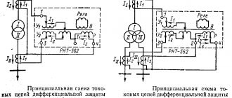
- differential current protection.
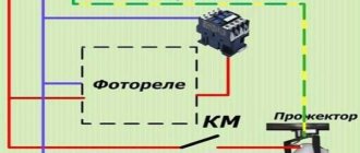
In this case, current relays can be connected according to various circuits (star, partial star, zero-sequence current filter, current difference).
React to direct, zero or negative sequence current, used to protect lines, generators, transformers, etc.
Purpose and types
A current control relay is a device that reacts to sudden changes in the amount of incoming electrical current and, if necessary, turns off the power to a specific consumer or the entire power supply system. Its operating principle is based on comparing external electrical signals and instantly responding if they do not coincide with the operating parameters of the device. Used to operate a generator, pump, car engine, machine tools, household appliances and more.
Photo – OptiDin OM-110
There are the following types of direct and alternating current devices:
- Intermediate;
- Protective;
- Measuring;
- Pressure;
- Time.
An intermediate device or maximum current relay (RTM, RST 11M, RS-80M, REO-401) is used to open or close circuits of a certain electrical network when a certain current value is reached. Most often used in apartments or houses to increase the protection of household equipment from surges in voltage and current.
Photo - diagram of RTZ - 50
The operating principle of a thermal or protective device is based on monitoring the temperature of the contacts of a specific device. It is used to protect devices from overheating. For example, if the iron overheats, such a sensor will automatically turn off the power and turn it on after the device has cooled down.
Photo - RST-80AV
A static or measuring relay (REV) helps close the contacts of the circuit when a certain value of electric current appears. Its main purpose is to compare the existing network parameters and the required ones, as well as quickly respond to their changes.
Pressure switches (RPI-15, 20, RPZh-1M, FQS-U, FLU and others) are necessary for monitoring liquids (water, oil, petroleum), air, etc. Used to turn off the pump or other equipment when the set values are reached pressure. Often used in plumbing systems and at car service stations.
Time delay relays (manufactured by EPL, Danfoss, as well as PTB models) are necessary to control and slow down the response of certain devices when a current leak is detected or other problems in the network. Such relay protection devices are used both in everyday life and in industry. They prevent premature activation of emergency mode, operation of RCDs (also known as differential relays) and circuit breakers. Their installation scheme is often combined with the principle of including protective equipment and differentials in the network.
In addition to these, there are also electromagnetic voltage and current relays, mechanical, solid state, etc.
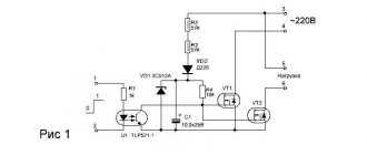
A solid-state relay is a single-phase device for switching high currents (from 250 A), providing galvanic protection and isolation of electrical circuits. These are, in most cases, electronic equipment designed to quickly and accurately respond to network problems. Another advantage is that such a current relay can be made with your own hands.
By design, relays are classified into mechanical and electromagnetic, and now, as mentioned above, into electronic. Mechanical can be used in various operating conditions, its connection does not require a complex circuit, it is durable and reliable. But at the same time, it is not accurate enough. Therefore, now its more modern electronic analogues are mainly used.
Photo - RT85
ILV connection diagrams
In the panel, the voltage relay is always installed after the meter in the break of the phase wire. He must control and, if necessary, cut off the “phase”. There is no other way to connect it.
Most often, for single-phase consumers, a standard circuit with direct load through a relay (+) is used.
There are two main circuits for connecting single-phase relays of the mains voltage regulator:
- with direct load through the RLV;
- with connecting the load through a contactor - with connecting a magnetic starter.
When installing an electrical panel in a house, the first option is almost always used. There are plenty of various ILV models with the required power on sale. Plus, if necessary, these relays can be installed in a parallel circuit and several by connecting a separate group of electrical appliances to each of them.
Installation is extremely simple. On the body of a standard single-phase relay there are three terminals - “zero” plus phase “input” and “output”. Just make sure not to mix up the connected wires.
Causes of problems
There are three factors that cause voltage drop:
- When the phase is shorted to neutral, 380 Volts will appear in the socket.
- If a zero break occurs and the load in the network is low, then the voltage will sharply tend to the peak.
- There may be a voltage imbalance in the phases.
Low voltage Source uk-parkovaya.ru
In the latter case, an unevenly distributed load leads to the fact that the busiest line will suffer. The voltage will drop to critical. And this is fraught with local problems in the technology itself. And, as a rule, if there is no surge protection relay on the line, then the refrigerator or air conditioner will be the first to suffer.
In rare cases, electricians are to blame for a zero break. The wire can be damaged due to inexperience and carelessness. More often the latter fades away from old age. The provided protection will de-energize the line and disastrous consequences will not occur. There will be temporary inconvenience until the network is restored.
But, if there is no voltage cut-off, then a real mess ensues in the house. In some rooms, the voltage in sockets drops to 50-100 units. In other apartments it rises sharply to 300-350. Moreover, the result is completely local and depends on the specific load on the home line.
A sharp increase in voltage Source uk-parkovaya.ru
As a result, some owners' household equipment simply stops working. Those less fortunate will have to take it for repairs. But after a critical power surge, it happens that repairing the device becomes unprofitable. And then all that remains is to buy a new one. And, as a rule, there is no one to file a claim with.

