Schottky diode components are a type of semiconductor devices that do not use the pn junction principle. The area of contact between the metal surface and the semiconductor material acts as a one-way conductor. Below we consider the characteristics of one of the popular 1n5819 models, its application, and lists Russian-made products that can replace this diode.
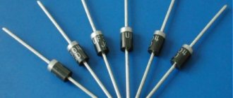
Case DO-41
general information
These parts received their name in honor of the German scientist W. Schottky, who is credited with determining the properties of the barrier region at the point of contact of the semiconducting element with the metal. Gallium arsenide often plays the role of the first in diode products. Sometimes a silicon semiconductor is used. Metal parts can be platinum or silver; gold options are less common.
Surface Mount Option
In terms of their parameters, these products differ in many ways from silicon diodes using p - n junction:
- They have a small junction capacitance. This makes it possible to operate at high frequencies and allows these components to be used to create digital circuits.
- When a Schottky product is connected directly, the voltage drops by an amount 2-3 times less than when a standard product designed for rectification is turned on. Because of this phenomenon, they are more productive in a direct current situation, since the lower drop value implies that the heat loss dissipated into the environment will be significantly lower. But, if the reverse voltage indicator increases significantly, surpassing the value of a hundred volts, the magnitude of the drop also increases and becomes slightly different from the situation when using a traditional diode. This effect determines the limits of the optimal operating voltage for this type of diode elements: it is better to choose them when the voltage is in the tens of volts.
- These diodes are also characterized by fast recovery, so they can be used in configurations that rectify voltages up to 100 kilohertz and above. Due to the absence of the diffusion process of third-party electric charge carriers, these diode components are characterized by increased performance.
Important! In a situation where the average current is equal to one unit of measurement (1 A), and the reverse voltage parameter does not exceed 40 V, the in5819 model is often installed. It is available in two versions. The SMD version for surface installation has a plastic housing and is marked SS14. The cylindrical version with long “antennae” leads intended for threading into prepared holes on the board also has a plastic body.
Traditional design of this diode
Specifications
The 1n5819 compares favorably with its conventional silicon counterparts due to its lower voltage drop when directly turned on, which contributes to the release of lower power dissipation in the form of heat. The Pn junction is replaced by a Schottky barrier, which has a very low electrical capacitance (110 pF), allowing the device to operate at high frequencies (up to 1000 kHz).
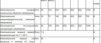
Maximum parameters
Let's consider the maximum parameters of the 1n5819 diode:
- reverse voltage (VRRMmax) up to 40 V;
- forward voltage drop across the diode (VF max) up to 0.6 V;
- direct (from anode to cathode) effective current (IF max) up to 1 A;
- junction operating temperature range (TJ) -65 … +150 oC.
Electrical parameters
The ability to quickly recover from switching makes the 1n5819 an indispensable companion for many logic integrated circuits. However, with increasing crystal temperature, the leakage current and forward voltage drop across the junction increase sharply. This feature is clearly demonstrated in the table of electrical parameters and is one of the main disadvantages of all Schottky diodes.
You can download the main characteristics of the 1n5819 diode in Russian using this link.
Analogs
The American SB140 from Vishay is a full-fledged analogue of the 1N5819. This is a copy of the old 11DQ04 from the Japanese company Nihon Inter Electronics Corporation. As a functional replacement you can use: 1N5822 (STM), MBR140P (ON Semiconductor), BYV10-40 (STM), but they have a different housing design.
KDSh2105V is a domestic analogue in plastic packaging KT-26 (TO-92) from the Belarusian enterprise Integral.
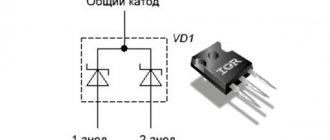
Characteristics of Schottky diode 1N5819
Diode SS14: characteristics
Both types of design in5819 have the same operating plan characteristics. It's worth noting here:
- average current value after rectification – 1 Ampere;
- the total capacity of the housing and the crystal element is 110 picofarads;
- the highest reverse operating voltage is 40 volts (the same figure for the peak value);
- AC reverse voltage value – 28 volts;
- operating temperature ranges from -65 to +125 degrees Celsius; thus, barrier elements can operate in a wide range of temperatures, including extremes.
Important! The identity or proximity of the peak and operating voltage values is a characteristic feature of Schottky elements.
Advantages and disadvantages
Despite its good parameters, 1n5819 is not capable of becoming a full-fledged replacement for conventional pn junction rectifier diodes. This is due to its design features and properties. It works well in high-frequency circuits and heats up less due to its low forward voltage drop. But there are also disadvantages that outweigh all these advantages.
Compared to conventional diodes, which are unable to operate in high-frequency modes, Schottky diodes have a much lower maximum permissible reverse voltage. They have much higher leakage current, which increases disproportionately quickly with increasing chip temperature. This can be clearly seen if you compare the parameters from the datasheets of these devices with each other.
Diode pinout 1N5819
Characteristics of in5822 Schottky diodes
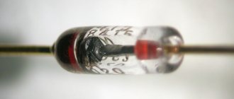
For a diode to work correctly, it must be correctly connected to the circuit being prepared. To do this, the master needs to correctly determine the cathode and anode poles of the product. The cathode marking on the version of the model under consideration, equipped with long leads, has the form of a light stripe applied along the perimeter of the cylindrical body from the corresponding end. It is often applied with silver paint. The anode is not specially marked in any way. The SMD version is also supplied with stripes.
For the diode component to function properly, the negative terminal, marked with a stripe, must be connected to the negative terminal of the current source (or voltage, depending on which circuit the diode is used in). The anode, in turn, is connected to a positively charged pole.
Diode element pinout
Part Description
1n5819 diode: characteristics
Externally, the electronic component is no different from an ordinary diode. Its miniature DO-201AD body is cylindrical in shape. It is made of heat-resistant black plastic. On the sides are two copper terminals called the anode and cathode. They are necessary to fix the 1N5822 on the printed circuit board and connect the part with other elements of the circuit. The terminals are covered with a thin layer of solder. If the part is new, then they have a characteristic silvery shine. After installing the diode in the desired location, the legs are shortened to the minimum size.
The part in question belongs to the category of so-called Schottky barrier diodes. Their main difference from conventional semiconductor rectifiers, like the 1N4007, is the low voltage drop when turned on in the forward direction. It is 0.2-0.4 V versus the typical 0.6-0.7 V for conventional silicon diodes.
This feature allows the 1N5822 Schottky diode to be used in circuits with higher currents. After all, the lower the voltage drop across the diode, the less power dissipated on it. This implies another advantage of this category of rectifiers. Their chip generates a small amount of heat, so the part body has smaller dimensions, and in some cases the use of radiators or forced cooling can be avoided.
Additional Information. By connecting two diodes in parallel, you can achieve an even smaller voltage drop. This in turn will double the maximum current allowed through such an assembly. This solution is often used by electronics manufacturers. Parts are also produced that already contain two diodes connected in parallel in one housing.
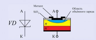
Another feature of Schottky diodes, incl. and 1N5822, follows from its structure. In this part, the usual electron-hole pn junction is replaced by a metal-semiconductor structure. This structure made it possible to significantly reduce the input parasitic capacitance of the element and, as a result, to use it in higher-frequency circuits.
Structure of a Schottky diode
Features of application
When considering the characteristics of the 1n5819 diode, you need to pay attention to its operational features and the limitations imposed by the design. The model is often used as a rod for shunting the terminals of low-power transistor devices. In those electrical circuits where there is a risk of increasing the reverse voltage value compared to that noted in the technical description, it is not worth installing such barrier diodes. When installed in such a circuit, they soon become unsuitable for further use. Options 1n5818 and 1n5817 are even more demanding on reverse voltage: the first model can only be installed in conditions where the parameter does not exceed 30 volts, and for the second it should be no higher than 20 volts.
Parts of the 1 n 5817-1 n 5819 diode series are used in the following areas:
- battery chargers;
- switching power supplies of different types;
- for receiving alpha, - and beta radiation;
- for shunting transistor devices;
- in high frequency rectifying devices;
- in the production of solar batteries;
- in neutron beam recognizers.
Important! Although these parts have a significant operating temperature range and can withstand temperatures up to 125 degrees Celsius, during installation you need to take care to remove excess heat from the plastic body of the element. A very high temperature can cause an uncontrolled increase in the reverse current, which is very dangerous, since it entails the disintegration of the junction or its breakdown.
Polarity of 1N5817 diodes
Very important points for the installation of any PCB components are the correct determination and observance of polarity. With the diode model under review, everything is simple in this regard - the side of the case where the cathode output is located is equipped with a strip of a different color (often light) that wraps around the case. The anode terminal is not specially marked in any way. On the rest of the body, laconic markings are applied with the same coloring composition used to make the strip.
Mounting the 1N5817 diode on the board
The components of the 1n5817-1n5819 diode series are installed by soldering using TNT technology. In this case, the pins are installed in specially prepared holes on the board. The body itself can be placed either parallel to the surface or perpendicular. As for the maximum temperature value, it should not exceed +250 degrees Celsius, its exposure time is allowed no more than 10 seconds. Low and high ambient temperatures also have restrictions: no less than -65 and no more than +150 degrees, respectively.
Closed Schottky diode
The diode element is considered closed in a situation where it blocks the passage of current. In some cases, such a diode installation is practiced purposefully. You can reliably assess how well an element conducts electric current by using a measuring device (ammeter or multimeter) and finding out the amount of current passing.
Open and closed diodes
Open Schottky diode
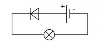
In the diagrams, diode elements are designated as arrows, demonstrating the direction of current flow in a situation where the diode is open. Under normal conditions, this situation is created by connecting the anode to the positive pole of the current (or voltage) source, and the cathode to the negative pole. In addition, it is imperative that the voltage exceeds the threshold at which the element begins to open (about 0.5 V). You can check the passage by measuring the current with a measuring device. An indirect indicator can be voltage - the measurement results must exceed the threshold and correspond to a direct connection.
Schottky diode device 1N5817
The cylindrical housings used for the production of diodes belong to the DO-41 type. They are made of molded plastic; tinned rod output elements with polarization are placed on the sides (bottom) of the cylinder. These rods are made from wire. In terms of flammability, diode bodies pass UL 94 category with specification V-0. This means that combustion ends after 10 seconds.
Peculiarities
For the production of ss14 diodes, rectangular SMA class packages are used. The letters SS in the product name indicate the following: the first – surface mounting, the second – the presence of a Schottky barrier. The terminals are made of tinning-treated brass. The cathode side is marked on the body, and different manufacturers designate it differently (dot, strip of a certain color, notch). Also, some companies shorten the model designation on the case to two digits - S4. The components are very lightweight - each unit weighs no more than 0.064 grams. The miniature size and features of mounting on a board are advantageous from the point of view of production processes, but make testing difficult - for this purpose the multimeter must be equipped with a special design.
Dimensions of Schottky smd parts
Important! On graphical representations of electrical circuits, such an element may be designated as standard for diodes or have some additional symbols. Accepted graphical representation of a surface mount Schottky diode on circuit diagrams
Accepted graphical representation of a surface mount Schottky diode in circuit diagrams
The name of the class of diodes is associated with the name of the German physicist Walter Hermann Schottky, who was the first to describe the transition between a metal surface and a semiconductor material. In the products under consideration, this transition is created through direct contact of these two materials. The typical P–N implementation involving the phenomenon of electron-hole conduction is not used in the SS14 model. Electric current is created by electrons themselves. In different models of Schottky products, silver, gold or platinum conductors can be used. The semiconductor component may be silicon or made of gallium arsenide.
The advantages of using such parts are significant performance and low resistance when installing the element directly, which minimizes the reduction in voltage on it. This makes it possible to mount these diodes in pulse-type devices. In addition, the working transition zone has a low electrical capacity, which allows the use of these elements in high-frequency installations. Diodes also have weaknesses: they have little resistance to situations where the maximum reverse voltage is exceeded; heating entails a sudden increase in the reverse current. These features are associated with the design of diode components.
Analogue 1N5819
Often when working with boards, the question arises of how to choose a domestic analogue for the 1n5819 component. There are no full-fledged substitutes on the market, but Russian manufacturers produce a number of products that can be used as an analogue. These are models KD268-KD273, as well as KD238.
We must remember! They are available in a slightly different housing design - T0-220. In Belarus, they produce the KDSh2105V diode, which has operational characteristics identical to 1n5819.
The diode in question is characterized by high performance and lowers the voltage less than standard products, which makes its use beneficial in a number of situations. When installing the product, you must determine the correct polarity.
Voltage drop across a Schottky diode
If you apply direct current to the diode, then the voltage will “settle” on the diode. This voltage drop is called the forward voltage drop of the diode. In datasheets it is designated as Vf, that is, Voltage drop.
forward voltage drop across the diode
If you pass direct current through such a diode, then the power that will be dissipated by it will be determined by the formula:
Where
P – power, W
Vf – forward voltage drop across the diode, V
I – current through the diode, A
Therefore, one of the main advantages of a Schottky diode is that its forward voltage drop is much lower than that of a simple diode. Consequently, it will dissipate less heat, or in simple terms, heat up less.
Let's look at one example. Let's take a 1N4007 diode. Its forward voltage drop is 0.83 Volts, which is typical for a simple semiconductor diode.
voltage drop across the diode in direct connection
At the moment, a current of 0.5 A is passing through it. Let's calculate its power dissipation at the moment. P=0.83 x 0.5 = 0.415 W.
If we look at this case through a thermal imager, we can see that its body temperature was 54.4 degrees Celsius.
Now let's do the same experiment with a 1N5817 Schottky diode. As you can see, its forward voltage drop was approximately 0.35V.
voltage drop across the Schottky diode when connected directly
When a current of 0.5 A passes through a Schottky diode, we get a power dissipation of P = 0.5 x 0.35 = 0.175 W. At the same time, the thermal imager will show us that the body temperature will already be 38.2 degrees.
Consequently, Schottky is much more efficient than a simple semiconductor diode in terms of passing forward current through itself, since it has a lower voltage drop, and therefore dissipates less heat into the surrounding space and heats up less.
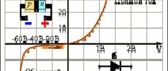
The forward voltage drop can also be viewed in datasheets. For example, the forward voltage drop across a 1N5817 Schottky diode can be found from a graph of forward current versus voltage drop across a Schottky diode
graph of forward current versus voltage
In our case, if we follow the graph-analytical method, we just get a value of 0.35 V
Video
Coffee capsule Nescafe Dolce Gusto Cappuccino, 3 packs of 16 capsules
1305 ₽ More details
Coffee capsules Nescafe Dolce Gusto Cappuccino, 8 servings (16 capsules)
435 ₽ More details
Toners for Brother printers
Schottky diode application
These electronic elements presented above can be found in our world almost everywhere: in computers, stabilizers, household appliances, radio broadcasting, television, power supplies, solar panels, transistors and in many other devices from all spheres of life.
In all cases, it increases efficiency and performance, reduces the number of losses in voltage dynamics, restores the reverse current resistance, absorbs the radiation of alpha, beta and gamma charges, allows you to work for a long time without breakdowns, and maintains the current in the voltage of the electrical circuit.
Without desoldering
Separately, you need to consider whether it is possible to test with a multimeter directly on the board without soldering the element from it. It all depends on the complexity of the scheme and the qualifications of the master. A product mounted on a board can ring through transformer windings, resistive elements, a burnt capacitor, or something else. Therefore, it is most often not possible to obtain more or less adequate indicators.
But it’s better to unsolder the element from the circuit. In addition, it is enough to “hang in the air” only one leg of the product, which takes 2-3 seconds. And after testing with a multimeter for the same period of time, the diode returns to its original position on the board.
The proposed circuit serves to simply determine the stabilization voltage rating of a zener diode using a voltmeter, as well as to determine its serviceability.
Nowadays, the industry produces an incredible number of different electronic components, and often when assembling a radio-electronic product, many difficulties arise in determining the rating of the component. The domestic industry has especially “distinguished itself” in this regard - in particular, zener diodes in a glass case sometimes have very similar markings, which are not possible to distinguish. A good example is the KS211 and KS175 zener diodes - sometimes there are marking options in which both look like a small output glass diode with a black stripe. They can also be confused, for example, with the D814 zener diode. Anyway, memorizing the color codes for zener diodes is not a good idea, considering how easy they can be checked.
To determine the stabilization voltage you will need a simple circuit:
Typically, the operating current range of low-power zener diodes is in the range of 1-10 mA, so the resistor resistance is chosen to be 2.2 kOhm. This is optimal for testing low-power zener diodes. To test powerful zener diodes, the resistance may have to be reduced - for this purpose, a jumper is provided in the circuit. To test low-power zener diodes, the jumper must be placed in the upper position, and to test high-power ones - in the lower position.
The optimal supply voltage is 25V.
If the zener diode is connected correctly - anode to X1, cathode to X2, then the voltmeter will show its stabilization voltage, and if incorrectly - some very small voltage near zero. If with one connection the multimeter shows a minimum voltage, and with the other - a maximum equal to the voltage of the power source, then the radio element under test is either a simple diode or a zener diode with a stabilization voltage higher than the voltage of the power source. If you are sure that it is a zener diode, you need to increase the source voltage to the expected value and check again.
If the voltmeter shows the minimum voltage, or the supply voltage for any connection, then this zener diode or diode is faulty.
If the stabilization voltage is displayed for any connection, it means it is a two-way zener diode.
In a similar way, you can check the serviceability of diodes and LEDs, only the polarity will be opposite
The good thing about this method is that it allows you to find out the voltage drop, which can be very important. When checking LEDs, you must remember that some LEDs are very sensitive to excessive reverse voltage, so it is advisable to set the source voltage when checking them no higher than 9V