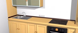
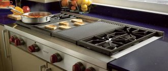
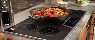
Among gas, electric heating stoves, glass-ceramic and induction hobs, the latter are the best solution for household chores. They have the same advantage as gas ones, that is, heated products quickly respond to changes in the power of the “burner”. They are also much safer: gas does not escape when cracked, and heating panels do not reach too high ignition temperatures, although they may naturally be hot.
The only problem is the connection. Theoretically, it should be carried out by a professional electrician, especially since the warranty card for the device contains a clause for connection by a qualified electrician, confirming the correct implementation of connections to the network.
However, many are not born themselves, having knowledge of electrical engineering at the professional level. Perhaps you also feel the desire to buy an induction stove instead of a gas stove and would like to do everything yourself (again, saving...). The article below provides information on the different connection options and types of induction cooktops.
Induction hob power
The standard power of the induction hob is 7.2 kW. What does it mean? This is the maximum power consumption of the heating plate. When used daily with two or three burners, the stove will consume less energy. It will all depend on how quickly you need to heat up your food once you get home.
How is power converted into electric current?
1.Single-phase installation - in free conversion it will be:
I = 7200 W / 230 V = 31.3 Amps.
2. Three-phase networks with two phases are most often used. Each phase supports two heating fields with the same total power. Thus, for each phase the power is about 3600 W and the current is:
I = 3600 W / 230 V = 15.7 Amps.
Even if full power is rarely used, the electrical system must be prepared for a situation where all the "burners" are operating at maximum.
Number of phases
The installation of all new European-made models is designed to connect equipment to a network with a different number of phases. In our homes there are two standards: a three-phase network with 380 V and a single-phase network with 220 V. The choice of the necessary connection diagram depends on the electrical wiring in the house.
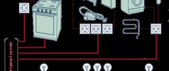
The standard hob circuit is represented by a terminal group consisting of five items, marked for convenience with numbers, and one grounding, which is indicated by the icon:
The following symbols are used in electrical engineering:
- phases are designated as L1, L2, L3;
- zeros – N1 and N2;
- grounding marked PE.
Having understood the connection diagrams and wires, you need to study the instructions. The manufacturer's recommendations list all connections and describe in detail the main installation steps. After the selected scheme, we move on to practice.
Before buying an induction cooker
First you need to find out what maximum power the wiring supplies to the house/apartment.
If the power of the network is lower than the power of the stove, there is a chance that it will regularly blow out the main fuse (on the stairwell or in the panel) or - in the worst case - it will overheat and the power cord will burn out. For example, in a standard Khrushchev building, the contract power for one apartment, that is, the maximum power that can be consumed by all devices in the house, is 5.5 kW. And this is 2 kW less than the maximum power of an induction hob. Not to mention other devices that you also use while cooking.
If there is a problem with the maximum current, then buy an induction hob with a lower power or with a function to reduce the maximum power. This is a much simpler option, although the lack of full power will result in a decrease in heating rate.
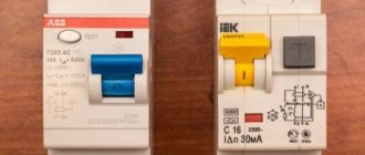
After solving the above problem, a cable with the appropriate cross-section must be laid from the switchgear to the induction hob and this cable must be protected by a separate circuit breaker (read about circuit breakers here) with the appropriate current rating.
Required materials and tools
Before performing installation work, you must purchase the following materials and tools:
- a screwdriver with a dielectric handle;
- electric cutters;
- combination pliers – crimping;
- cable type VVG or NYM;
- socket and plug for 32A - 40A included;
- PVA cable for connecting the hob to an electrical plug (if not included with the hob);
- differential machine;
- NShV tips;
- terminal block or GML sleeves;
- indicator screwdriver.
If you do not want to install an additional socket and plug to connect the hob, the cable coming out of the differential machine can be routed from the input panel without a socket and plug directly into the induction panel.
Single-phase network 220 V
This case applies mainly to apartments in which the owner decided that during renovations or just because it is worth installing an induction hob instead of a classic gas stove. What does this have to do with repairs? Of course, this is not a necessary condition, but in most cases the 220 V network is not ready to accept such an energy-intensive consumer, and it will be necessary to lay an additional cable from the switchgear to the induction hob and slightly modernize the distribution board.
Connecting an induction hob in a single-phase installation without prior preparation and checking the existing network is risky! An induction hob is not a refrigerator! Induction consumes a lot of electricity, more than any device in the apartment. You need to be sure that the power grid will be able to withstand such a load.
- Firstly, for induction, a separate cable must be used coming from the distribution device, intended only for this purpose.
- Secondly, the cable must have a cross-section adapted to the power of the board.
The instructions for some stoves state that the protection must be at least 30 A and the cable with a cross-section of 4 mm2. However, to improve wiring safety, it is better to use 25 A protection (such as a B25 switch).
Let's move on to the options for connecting the stove. The following diagrams are prepared based on the connection methods for individual models selected by the manufacturer. Always check the instructions before connecting your model.
Connecting the plate to the outgoing cable
In this case, the plate is a closed box from which a cable, most often 5-wire, is brought out. The most common are:
- Black and brown conductors - phase
- Blue and gray wires are neutral
- Yellow-green wire – protective
See examples of drawings from the instructions for the induction panel above.
When the power cord has an inappropriate cross-section
If the power cord has a cross-section of 2.5 mm2, it must be protected using a switch with a lower current rating, such as B16. In this case, it is worth buying an induction hob with limited energy consumption so that the maximum current switch does not trip when using 3 or 4 heating fields.
There are opinions that each induction hob has a controller that takes into account that the network is single-phase and does not allow half heating at full power or intelligently switches them if they are all working at once, that is, the consumption of 7.2 kW in a single-phase installation is only on paper.
However, not every induction cooker, when you connect it to single-phase weak wiring, automatically reduces energy consumption. If the manufacturer does not include such information in the instruction manual, it should be assumed that if 4 burners are turned to the maximum heat level, the induction hob will consume approximately 7200 W of energy in total.
Useful: How to connect a programmable electronic timer to the network
Connecting a plate with clamps instead of wires
If the stove model has a terminal with terminals located at the bottom instead of wires, it can be directly connected to the junction box.
How to connect a plug to a cable
If the plug has four contacts, then when connecting they must be connected to the marked colored wires of the cable. However, there is another option. If the socket is three-pin, a problem arises - four wires when there are 3 pins. The solution is simple - we twist the black and brown wires from the phase together and connect them to the “Phase” contact.
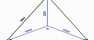
Three-phase network 380 V
The most common solution used by manufacturers is to power the stove not with three, but with two phases. The reason is simple. An induction cooker is not a three-phase motor, where strictly 3 lines are needed. An induction hob is a system of 4 independent elements - heating fields.
The easiest way is to separate them so that two fields are powered from one phase and two from the other. For example, it might look like this:
- Field 1 – power 1800 W (phase L1)
- Field 2 – power 1800 W (phase L1)
- Field 3 – power 1400 W (phase L2)
- Field 4 – power 2200 W (phase L2)
The fields are divided so that two average values are supplied from one phase and the smallest and largest from the second phase. Both of them have ~3600W of power, which is about 16A of current.
Connecting a plate with wires (2 phases)
As you can see, in this case the gray power cord (L3) is not used. Examples of drawings from the induction hob instructions related to the above diagram:
The unused cable is a gray power cord that should be insulated.
Connecting the board with terminals (2 phases)
Sometimes in such cases it is necessary to establish a connection between N terminals on the board. It can be made in the form of a plate that comes with the stove and only requires tightening the wires with a screwdriver.
Connecting a plate with terminals instead of a cable (2 phases) is a solution often used in practice
This is what a connection diagram looks like, which is often used in real conditions. During the installation phase, an induction hob is used, so the cable from the switchgear ends in the installation box. If the induction cooker comes with a cable, it is output to the box; if not, you need to buy an OMY cable (ShVVP) 5 x 2.5.
In addition, the unused phase (in this case L3) is also connected to the oven to ensure even loading of the phase. The oven can also be supplied with a separate 3 x 2.5 cable from the switchgear (and connects to a single phase overcurrent switch). Then, if one of the devices is damaged, the other can be used without any problems.
Complete three phase network for connection
If you are still in the construction stage of your home, you will most likely not have a selected induction cooktop model during the electrical wiring installation. But it’s worth thinking about one thing in advance. Will it be a standard 7.2 kW stove or a higher power 10 kW. Higher capacity stoves are larger and require all three phases to be supplied.
In this case, the possibility of powering the furnace from the distribution box is excluded. You run a separate wire from a switchgear designed just for the induction cooker.
Connection problems
If the panel behaves abnormally after the first start-up, for example, turns off and turns on spontaneously, you do not need to immediately worry about incorrect switching. The stove may be childproof. It happens that spilled water on the sensors causes malfunctions. The same thing happens when you start a cold stove in a warm room.
Modern hobs have a pan recognition function. They simply don't turn on unless there is a metal object on the burner.
There are also cases where protection is triggered. For example, when three-phase panels are connected to a regular outlet, some of the burners do not turn on (H is displayed).
Advice on how to avoid problems is quite expected. Before connecting the device, you should carefully study its data sheet and all the manufacturer’s recommendations. With careless installation or an incorrectly calculated power system, the following problems occur.
- Overheating with risk of fire when using conventional 16A sockets for stoves with power above 3.5 kW.
- Incorrect protection system, risk of short circuits and overheating of the wiring. For example, installing only a simple machine without an RCD.
- Danger of short circuits and fire if the cable cross-section is incorrectly calculated, for example, connecting a 7 kW oven with a 2.5 sq. mm wire.
- Switching the panel power line directly to the distribution box in the kitchen.
To summarize, I would like to note that the installation of the hob involves electricity, so during installation you will need certain skills. The safety of people also depends on proper connection. If there is the slightest doubt, it is better to entrust the connection of equipment to professional craftsmen. The same rule applies to eliminating breakdowns of induction cookers. Do-it-yourself repairs are only possible if you have the appropriate knowledge and experience in repairing equipment.
What connectors to use for the oven
To save as much space as possible and not fill the box with wires, it should be at least 10x10x5 cm. There is no need to save space because the unit will be covered by kitchen furniture.
To prevent the wires from being pulled, it is better to make loops at the ends of the wires (picture on the right) when connecting. As you can see in the above pictures, a special terminal block with screw terminals is used for three-phase conductors, neutral conductor and protective conductor. Its advantage is that after opening the lid you can see everything connected to it.
The rated current, that is, the maximum current that can flow through each terminal for a long time, for a single-phase network should be at least 32 A.
The use of spring terminal blocks for three-phase systems is not a problem and can be used quite well. They have a rated current of 24 A. But in a single-phase network, this is usually not enough to reliably connect an induction hob - it is better to use screw terminals.
Useful tips from the master
- Carry out installation with joint sealant.
- The socket must be able to withstand the power of the appliance. Otherwise, his work will put you in danger.
- Choose a socket from proven materials, do not skimp on it.
- Clean your panel frequently to prolong its life and prevent damage.
- To connect, draw a separate line.
- Use a multimeter to check the connection.
- When connecting yourself, it is better not to experiment and not pair devices from different manufacturers.