How is power supplied (and disconnected) to electrical installations or power lines (of course, we are talking about local wiring, not high-voltage lines)? Using various types of switching devices. These can be plug devices (plug-socket), manual or automatic safety switches, electronic control circuits. It is practical and safe to use remote switching devices such as a modular contactor.
Let’s immediately dispel the false opinion: such switches (switches) are not strictly industrial devices. AC contactors are widely used in everyday life. And not only in private houses, but also in apartments.
Design and principle of operation of the contactor
Based on the name, this is a group of contacts designed to connect electrical lines. The main application is a modular contactor that switches power lines. If in a regular switch (even an automatic protective one), closing and opening occurs manually, AC contactors are controlled remotely.
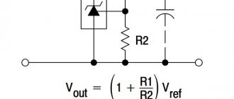
Let's consider the circuit of a simple contactor, without interlocks and protective modules.
For those who are more or less familiar with electrical engineering, it is not difficult to understand the principle of operation. The basis of the power group is the contacts indicated in the diagram by the letters “L” and “T”. Depending on the design, the system may simultaneously include one, two, or more pairs of contacts. In order for the connecting conductor strip to press against the fixed contacts, force is required. In conventional switches, this is a mechanical device driven by the operator. Our circuit is triggered by an electromagnet. When control voltage is applied to coil A1-A2, the solenoid is retracted and the power (operating) contacts are closed.
To ensure reliable and safe opening, a return spring is provided.
After removing power from the control winding, the return spring instantly removes the contact strip from the power terminals.
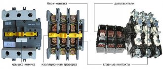
What is inside
Despite the apparent complexity and cumbersomeness of the design, the element base is simple:
- contact group made of copper (brass) alloys, designed for a certain resource;
- “T” shaped contact strip directly connected to the electromagnet solenoid;
- an electromagnet coil made for a specific contactor model;
- dielectric housing, which performs not only protective, but also load-bearing functions;
- arc extinguishing elements that are installed in the switching mechanisms of electrical installations with high current consumption.
In fact, the design is not much different from a conventional relay. There are also normally closed, normally open, and switching circuits (in which both types of contact groups are present). At the same time, according to the technical requirements of GOST, the modular contactor must have only one rest position (the state of the contact group in the absence of external control pressure).
When mechanical action is applied to a conductive strip (or group of strips), one or more contact pairs are closed (opened).
Thus, with the help of direct or remote influence, it is possible to control the power of electrical installations or power lines.
Parameters and technical indicators
The main indicators of electromagnetic contactors include the following:
- Number of main contacts. For direct current devices their number is 1-2, for alternating current - 2-5.
- Indicator of the current rating in the power circuit.
- The value of the maximum switching capacity of the device. Indicates the maximum current that can be switched off by the contactor without loss of performance.
- The rated voltage of the power circuit is no more than 660 V, the control circuit is 12, 24, 48, 110 and 220 V. Based on these data, we select the desired device.
- Resistance to switching wear of starters, up to 2 million cycles. The device must withstand the specified number of switching operations under the influence of current in the power circuit, and be suitable for subsequent use.
- Resistance to mechanical wear, discussed above. Indicates the number of operations without current in the power circuit. For contactors, this figure is 10-20 million cycles; the required device is selected based on it.
- Duration of own switching time. This is the time period from the moment of switching on (the command is given) until the moment when the contacts are completely closed.
- Duration of own shutdown time. It starts from the moment the shutdown command is given until the electric arc is completely extinguished.
- The value of current characteristics on additional contacts, their number and type. According to their functions, they can be of closing or breaking action.
Purpose of contactors
These devices can be divided according to their main characteristics, although the scope of application is virtually unlimited.
Types of contactors by purpose
- Remote switching devices (switching off, switching). When operating a complex of electrical installations, it becomes necessary to implement a certain power supply algorithm. Manual control: button, switch. The operator gives a signal at the right moment, the AC contactors are activated, switching the power according to a given operating pattern. For example, by pressing one button you can start an entire plant: conveyor, machines, lighting, ventilation system. By connecting many contactors in a certain way, it is possible to automate the power system on the control circuit (in this case, starting commands are given manually). In automatic mode, the command is given using an electronic circuit. The program controls production cycles at the right time, starting and stopping electrical installations. At the same time, any linear contactor can be equipped with a protection function: for example, a limit switch or thermal relay. When certain emergency conditions are created, the power to the coil is cut off and the operating contacts are opened.
- Switching on a powerful electrical installation using a low-current line, or again with a button (switch). A typical example is an electric motor starter.
It would seem, what does a modular contactor have to do with it: what is it for if you can use a button or a switch? Indeed, power can be supplied to the electrical installation directly using the contacts of the button. However, for a reliable connection of a powerful consumer, the contact group and the closing mechanism must be massive, and great force must be applied when turning on. The same force must be used to de-energize. This is not always convenient, especially in an emergency. Therefore, the device with which the operator directly works is compact, it is designed for low current (the consumption of the contactor coil is small), and a small force is required to activate it, especially on the off button. And the linear contactor itself can be quite large, and it operates instantly. Another reason why power separation of control and power lines is used is the high frequency of on and off cycles. For example, electric vehicles. The driver presses the accelerator pedal up to a thousand times per shift. If you equip the lever itself with power contacts, it will be inconvenient to use. Therefore, the pedal only supplies a weak current to the coil, and the line contactor starts the powerful electric motor.
Many of you, being near the driver's cabin, have heard regular loud clicks when pressing the pedal. This is exactly how a line contactor works.
Various drive types
- Electromagnetic is the main type and the most common. We discussed the principle of its operation in detail at the beginning of the article. Unless you can focus on the holding mechanism of the working coil. Most push-button (magnetic) starters do not have a locking button. That is, after the operator removes his finger, the power to the electromagnet should disappear. The design of most starters takes this point into account. There is a contact group on the end plate pusher that closes the solenoid circuit. While the entire electrical installation is working, there is power on the coil. If the voltage drops for a short time (emergency situation, or the disconnect button is pressed), all circuits are broken and the switch is turned on again. This adds safety during operation of the mechanism. After an uncontrolled power restoration, the electrical installation will not start until the operator decides to turn it on.
Information:
- When applying direct voltage (ordinary switch), dangerous situations sometimes arose:
the power is lost (line failure), the electrical installation is de-energized;
- the working day is over, the switch remains closed (the machine is not working, everyone has forgotten about the accident);
- power on the line is restored, machines, heating elements, etc. begin to work in the deserted workshop.
The use of contactors eliminates such situations.
The operating principle is the same, only the high pressure pulse acts as a control command. Such devices are widely used on railway locomotives, or other installations where pneumatics are present.
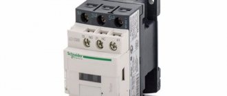
What it is
A contactor is an electrical magnetic device necessary for turning on and off the operation of various electrical devices at a distance (they are also called starters). Previously, this device in electrical engineering was used only to control the engines of electric locomotives and other machines, but now they are widely used in electronics.
Photo - MK class contactor
Contactors can be classified according to several criteria:
- Passing current. Many devices are designed to work exclusively with direct or alternating current, but there are also combined ones;
- According to the characteristics of the local electrical circuit. Contactors must be selected according to current strength and voltage. At the same time, there are household appliances with lower ratings and industrial ones, in which the voltage can reach up to 2000 volts and the power up to 5000 amperes;
- By the number of contacts and poles. There are two-pole, three-pole and other devices;
- Some starters are equipped with latches so that the magnetic contactors can be mounted on a DIN rail, and some do not.
Technical characteristics depend on what types of electromagnetic contactors are used. Let's consider the main ones:
- The working coil can have a voltage from 12 volts to 660, while the current frequency should not exceed 60 Hz;
- Any contactor can have from 1 to 5 poles;
- Many imported AC devices operate with a frequency of up to several thousand Hertz, while for DC models this figure can reach up to 10,000;
- On average, the service life of a contactor is up to 5 years;
- Coils can have different control options, so starters or, as they are also called, relays of this type are actively used in lighting systems, alarm systems, to control the operation of a diesel locomotive, etc.;
Types of contactors by installation method
Unframed or specialized devices (for example, a line contactor in a trolleybus) have no design restrictions and are developed based on functionality and safety considerations. There are also special designs created for certain electrical installations. Such switches are not used in domestic conditions, since they require separate locations.
For ease of use in standard electrical panels, standard modular designs are used for mounting on DIN rails.
They fit perfectly into the overall energy supply system of a home or office, if their use is provided for by the project.
Markings and types
There are several most common switches. The designation on the surface of the device helps to distinguish them. The brand is also indicated by the certificate and passport of the device. We suggest considering the most common ones:
- KT and KTP are crane contactors operating in direct and alternating current networks. They have extremely high wear resistance - up to several million cycle repetitions. The current frequency should not exceed 50 Hertz, voltage up to 380 Volts;
- KMI are small starters that are used to control the operation of asynchronous motors such as AIR, etc. They operate in a network where the current does not exceed 9 - 95A. The main feature is the ability to install switches in unfavorable areas with high levels of humidity and dust. Their analogue is a device of the KTE 400A EKF class, but in it the maximum permissible current reaches 400 A;
Photo - starter KM-2211 - The purpose of electromagnetic switches of the KTI type from IEK and ABB is similar to KMI, except that they control the operation of three-phase asynchronous motors. In other words, they have a wider range of action. They quickly switch the load (it takes approximately 2 seconds to change modes). Operates up to 660 volts;
- CNEs are used in current networks; they can be marine or tropical. They can be installed on ships, therefore they are widely used at various marine enterprises and motor ships;
- PM and PML belong to household starters, with a current strength of 2 amperes. Quite common in alarm systems and illumination. Their analogues are electro-pneumatic switching devices;
- Thyristor devices of the TKPM-121, KTP-121, KPD-121 series are designed for switching crane mechanisms. They operate under voltages up to 550 volts and frequencies up to 50 hertz. Production is carried out at the IEK plant;
Photo - TKD - Among the imported devices, we can highlight Siemens electromagnetic contactors, whose operating parameters allow them to be used for connecting and monitoring foreign machine tools;
- Starters of the KPV and KTPV types have a magnetic method of eliminating the arc, which is a huge advantage compared to other types. They are actively used for traction stock, electric vehicles and other complex mechanisms.
Where can I buy
You can purchase equipment as quickly as possible at your nearest specialized store. The optimal option, in terms of price-quality ratio, remains purchasing from the AliExpress online store. Mandatory long waits for parcels from China are a thing of the past, because now many goods are in intermediate warehouses in destination countries: for example, when ordering, you can select the “Delivery from the Russian Federation” option:
| AC Modular Contactor, 2P, 25A, 220V/230V, 50/60Hz | GEYA automatic modular contactor AC230V, 4P, 25A, 4NO, 2NO2NC, 3NO1NC, 50/60Hz | GEYA household contactor with manual control, 2P, 16/20/25A, 2NO/2NC, 220V |
| AC Modular Contactor 4NO/2NO2NC/4NC, 4P, 16/20/25A, 220V, 400V, 50/60Hz | Modular AC Contactor CT1-63 | Modular contactor TOCT1-25 |
Main characteristics
In order for the starter to work correctly, you need to follow certain installation rules, know the basics of devices with relays and select magnetic and reversing device circuits. Contactors and starters operate for a short time and devices with an open contact are most often used. Some have a signal circuit built into them and are designed for devices with consumption from 0.28 to 12 kilowatts, others for from 5 to 70 kilowatts and are capable of operating with a voltage distribution of 220 or 380 V.
Device options are divided into:
- open;
- protected;
- dust- and water-proof;
- dust-splash-proof form.
The PME starter contains a TRN “relay”, and the PAE model differs in the number of relays. If full voltage is supplied, the device's coils operate reliably. the main part of the devices has nodes:
- core;
- electromagnetic coil;
- anchor;
- frame;
- mechanical sensor;
- contact groups, central and additional.
The design may include an additional assembly consisting of a protective relay, an electrical fuse, an additional terminal set and a starting device.
The electromagnetic coil with turns is designed to transmit voltage up to 650 V. The coil is located in the heart, and most of the power is distributed to the power part of the springs. In the normal state, the contact is open and the springs are held in the upper position and hold the magnetic conductive sections.
There are starters that limit overvoltage; they are used for semiconductor systems. The coil begins operation of the alternating current system; the type of current and characteristic do not affect the operation of the installation.
Modular contactor connection diagram
There are no universal solutions; each switch is connected to power and control lines in accordance with the manufacturer's recommendations. It’s not difficult to figure this out; a detailed description (as well as safety measures) is required in the passport and on the device body.
Moreover, the same contactor (meaning model) can be used for various projects and local solutions. To understand the development methodology, consider the connection diagram for a switch in push-button starter mode for an electric motor.
You can also turn on a powerful electric heater or water boiler. It does not matter whether the contactor is single-phase or three-phase. Fundamentally, only the number of contact groups influences the switching scheme.
Starter control
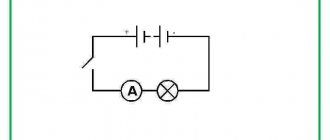
The operation of the device largely depends on the area of its use. To control a three-phase electric motor, the following connection diagram for an electromagnetic contactor is used:
Photo - control diagram
After pressing the start button, an electric current begins to flow through the coil, which creates a magnetic field. Thanks to this, the main contacts are attracted and closed. Accordingly, after using the “Stop” button, the movement of the directed particles stops - the contacts open, the engine stops. Please note that after stopping the terminals are not fixed, which is why starters often break. In this case, repair of the switching mechanism itself will be necessary.
Photo - contact blocking
If you want to buy electromagnetic MK contactors for blocking individual equipment, then the presented diagram will help you. In the presented drawing, an important role is played by the starting attachment, which, after stopping the starter, fixes its main contacts, preventing them from connecting for a long time. This option is considered more reliable than the first.
Electromagnetic contactors are sold in specialized electrical equipment stores, and the price depends on the class of the starter. For example, the cost of a standard 10 Ampere CT varies between 400 rubles, and a specialized Siemens one - 800.
Video: how to connect an electromagnetic contactor
Design Features
The main purpose of vacuum contactors is to turn on/off various devices and switch them with AC power circuits. A DC electromagnet is used to perform work processes. Each such contactor is equipped with a sealed arc extinguishing device, which serves as a vacuum chamber. In it, the switched circuit is turned off in a vacuum environment for 1-2 half-cycles.
This design became the basis for the creation of three-phase vacuum contactors with ratings of 160, 250, 400 and 630 A at rated voltages of 660 and 1140 volts. They are highly resistant to wear, and the number of operating cycles is 600 and 1200 per hour.
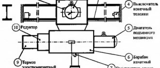
The device uses a block-type design with an insulating base (1), where all components are located. The diagram shows the elements - a vacuum chamber (2), an anchor axis of rotation (3) and the armature itself (4), a pole piece and core (5 and 6), a coil (7), an electromagnet base (8), and a tripping return spring (9), the axis on which the movable contact (10) rotates. Ultimately, the contactor consists of three arc chutes, an electromagnet and block contacts.
The vacuum chamber contains the main contacts, made in a cylindrical shape. There is a gap of 1.2 mm between them, gradually increasing to 2 mm. During operation, the gap can be adjusted once.
We should separately consider a vacuum chamber for arc extinguishing, which is distinguished by high arc-extinguishing and insulating properties, increased breakdown voltage between contacts, and rapid restoration of electrical strength in the intercontact gap.
The diagram below shows all the camera parts and how they interact with each other. The moving contact (1) is connected using a tripping spring to the electromagnet armature. The fixed contact (2) is installed in a housing (3), made in the form of two flanges. Metal-ceramic plates (4, 5) are fixed to the contact surfaces. To connect the moving contact (1) to the bottom of the chamber, a corrugated bellows (6) made of stainless steel is used. Thanks to this device, the moving contact moves without breaking the seal of the vacuum chamber.
Scope of application and purpose
Modular contactors are universal devices suitable for industrial and domestic use.
In both cases, the devices are used to control ventilation and heating systems. For this purpose, the devices are supplemented with temperature sensors and time relays, which ensure operation at certain time intervals or at a given temperature. In addition, the devices help control the operation of pumps, lighting fixtures and other equipment. Also, using a contactor, you can organize an ATS system - automatic transfer of reserve. The design of the device allows for the implementation of a conventional and reversible electric motor control circuit.
Price overview
You can buy a modular contactor in any city in the Russian Federation and CIS countries; the price depends on the model and brand of the device.
| City | Cost of TDM KM63/2, USD e. |
| Voronezh | 20 |
| Ekaterinburg | 21 |
| Kyiv | 23 |
| Krasnodar | 20 |
| Nizhny Novgorod | 21 |
| Novosibirsk | 21 |
| Tyumen | 21 |
| St. Petersburg (SPb) | 23 |
Before purchasing, be sure to check the contactor passport and quality certificate of conformity.