Installation of modular pin grounding is an excellent option for installing a grounding system (grounding loop) in a private home. In this case, the duration of installation work is significantly reduced. The functions of the grounding device are not inferior to the grounding loop made according to the triangle diagram using welding and other similar systems (linear, deep, electrolytic, etc.). In this publication we will show in detail how to install modular pin grounding with your own hands and what advantages it has over other systems.
Design features
What is such a system and what does it consist of? The device consists of one and a half meter steel pins, which are treated with copper and connected using couplings. The kit also includes a brass clamp that connects the horizontal and vertical contours. Below is a diagram of the design.
The modular pin grounding system is installed as follows: a landing pad (nozzle) is mounted on the top of the pin, which in turn is connected to the coupling. The attachment is necessary to transmit the force of the vibrating hammer. A steel tip is installed on the lower part of the structure. It makes it easier to drive the unit into the ground. There are several types of tips, the scope of which depends on the hardness of the soil.
In addition, the kit comes with a special electrically conductive liquid paste, the purpose of which is to protect against corrosion and constantly maintain electrical resistance during operation. Electrically conductive paste is applied to all threaded connections of the structure. You can also use special moisture-proof adhesive tape to prevent corrosion. It is resistant to acids, salts and gases, and does not allow moisture to pass through.
Examination.
Done, you now have a ground connection. All that remains is to check its effectiveness. To do this, you can, of course, take any heating device with a power of 2 kW or more and connect one wire to a phase, and the second to a new ground; if it works normally, then everything is fine, but this is not a very good test. Therefore, we will check using MPI-520 (electrical safety parameter meter for electrical installations).
MPI-520 (meter for electrical safety parameters of electrical installations). The value shows 26.8 ohms. That is, it is included in the re-grounding tolerance at 400 V, namely it should be less than 30 Ohms. This is when using 2 pins of 1.5 meters each.
Installation stages
Modular-pin grounding is installed according to a simple principle. First of all, the tip is put on the first pin. But before installation, it should be treated with electrically conductive paste against corrosion. We screw the coupling onto the other end and also treat it with anti-corrosion paste. The landing pad is then screwed onto the device to apply the vibratory hammer forces.
We place the assembled modular-pin grounding in a pre-prepared hole in the ground. You need to screw it into the ground as deeply as possible with your own hands. Then you need to connect the vibrating hammer to the network and place it on the rod site. Thus, the pin is immersed in the ground along its entire length. You only need to leave 20 cm in order to connect another rod.
After this, you should measure the grounding resistance. To do this, you need to remove the landing nozzle and connect a special device, an ohmmeter, to the place where it was located:
When the first rod is located in the ground along its entire length, the landing attachment for the vibratory hammer is removed and another pin is mounted through the coupling. A special clamp, which holds the pin in a vertical position, rises upward along the installed device. And the connecting coupling and attachment for the vibrating hammer are again installed on the mounted structure, after which the process is repeated.
Spread resistance should be checked after installing each vertical rod. The pins are installed until the required resistance is established. The figure below shows a diagram of the change in resistance depending on the length:
Next, you need to connect the horizontal ground electrode and the vertical conductor. To do this, a brass clamp is attached to the end of the rod that protrudes from the ground and a horizontal ground electrode is connected to it. A special plate is placed between the pin and the horizontal cable, which protects against corrosion when dissimilar metals come into contact. After the system has been connected, the connection points are treated with special adhesive tape. It serves as additional protection against corrosion.
Conclusion.
At the moment, this is the simplest way, in my opinion, for grounding. Does not require a welding machine or special skills. At a cost of 4 thousand rubles (if you take 2 rods), it fully justifies itself in dense soil. If the soil is loose, then it is better to use more rods. Efficiency is achieved through depth, not quantity. If you liked the article, then leave a comment and subscribe to the channel. You can also save the recording so as not to lose it. If you have questions or additions, please leave them in the comments.
Subscribe.
Article about the selection of UDT.
Article about cable selection.
Article about SIP.
Advantages and disadvantages of the system
Modular-pin grounding, like any system, has its pros and cons. Compared to the classic and standard circuit, pin grounding has the following advantages:
- ease and simplicity of installation;
- occupies a small area;
- installation is carried out by a minimum number of workers (1–2 people);
- installation occurs without welding, since all connections are made using couplings;
- thanks to the vibratory hammer, there is no heavy earthwork;
- modular-pin grounding is resistant to corrosion, as it is treated with special lubricants and coatings, thanks to which they last for several decades;
- regardless of the ground, the pin system is easily driven into the ground;
- structural elements are manufactured industrially, due to which they are of high quality and are ready for immediate installation without additional preparatory work.
Modular-pin grounding has one significant disadvantage - its high cost. But, despite this drawback, the system is beneficial if you take into account all its advantages.
The industry produces a wide variety of kits that combine the elements necessary for reliable and high-quality installation. Modular-pin grounding has an important purpose - it protects the house from fire, and people in the room from electric shock.
What is grounding?
Grounding is a set of devices (grounding conductor, grounding wire, grounding bus), which, if a dangerous potential occurs on the body of an electrical device, will protect a person or animal due to the “draining” of the dangerous potential into the ground.
Grounding is a set of devices (ground electrode, ground wire, ground bus). Rough diagram of the author of the article.
It is important to understand that only one grounding is good and increases electrical safety, but when combined with a RCD (residual current device): RCD or RCBO, this system will significantly increase your safety. Since, when a dangerous potential appears, the UDT will instantly turn off the voltage. It is possible to use grounding without UDT, but vice versa it is not possible. It’s only possible if the UDT is electromechanical, but that’s just my opinion. I wrote an article about this (link below).
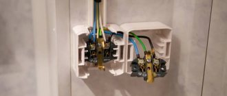
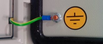
The grounding wire is green-yellow in color, and its cross-section should be no less than that at the input. If at the input you have a 6 mm² wire at phase and zero, then for grounding you should take 6, or better yet 10 mm². The grounding bus (PEN) in the panel is the bus where all the grounding wires are connected.
Grounding bus (PEN) in the panel with a green-yellow grounding wire. The cross-section at the inlet is 10 mm², and the outgoing cross-section is 1.5; 2.5 and 6 mm². UDTs are also present in the form of RCBOs. Photo of the author of the article.
Do-it-yourself grounding schemes for private houses: 380 V and 220 V
When installing grounding loops, there is no significant difference between the 3-phase (380 volt) and single-phase (220 volt) circuit of a private house. But it is present in the cable routing. Let's figure out what it is.
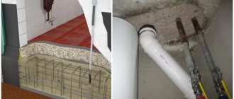
Proper entry into the house. This is how it should look ideally
With a single-phase network, a three-core cable (phase, neutral and ground) is used to power electrical appliances. A three-phase network requires a five-core electrical wire (the same ground and neutral, but three phases)
Particular attention should be paid to the connection - the grounding should not come into contact with zero
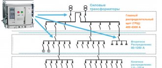
Let's consider the situation. 4 wires (zero and 3 phases) come from the substation, connected to the distribution board. Having arranged the correct grounding on the site, we insert it into the shield and “plant” it on a separate bus. The phase and neutral conductors pass through the entire automatic device (RCD), after which they go to electrical appliances. From the grounding bus, the conductor goes directly to sockets and equipment. If the zero contact is grounded, the residual current devices will trip for no reason, and such installation of electrical wiring in the house is completely useless.
The do-it-yourself grounding scheme at the dacha is not complicated, but it requires a careful and careful approach when performing it. It’s easy to do it for only one boiler or other electrical appliance. We will definitely dwell on this below.
The body of a gas boiler, like metal pipes, requires high-quality grounding to avoid sparks.
What is a ground loop in a private house: definition and design
A grounding loop is a structure of pins and busbars located in the ground that provides current drainage if necessary. However, not any soil is suitable for installing a ground electrode. Peat, loam or clay soil are considered suitable for this, but stone or rock are not suitable.
The circuit is ready. All that remains is to lay the tire to the wall of the house
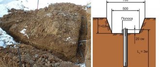
The grounding loop is located at a distance of 1÷10 m from the building. To do this, dig a trench ending in a triangle. The optimal dimensions are side lengths of 3 m. Electrode pins are driven into the corners of the equilateral triangle and connected by a steel bar or angle by welding. From the top of the triangle the tire goes to the house. We will look at the algorithm of actions in detail in the step-by-step instructions below.
Having figured out what the grounding loop is, you can move on to calculating the material and dimensions.
Grounding calculation for a private house: formulas and examples
Electrical installation rules (PUE) and GOST establish the exact framework for how many ohms the grounding should be. For 220 V it is 8 ohms, for 380 it is 4 ohms. But do not forget that for the overall result, the resistance of the soil in which the grounding loop is installed is also taken into account. This information can be found in the table.
| Type of soil | Maximum resistance, Ohm | Minimum resistance, Ohm |
| Alumina | 65 | 55 |
| Humus | 55 | 45 |
| Loess deposits | 25 | 15 |
| Sandstone, groundwater depth deeper than 5 m | 1000 | — |
| Sandstone, groundwater no deeper than 5 m | 500 | — |
| Sandy clay soil | 160 | 140 |
| Loam | 65 | 55 |
| peat bog | 25 | 15 |
| Chernozem | 55 | 45 |
Knowing the data, you can use the formula:
Formula for calculating rod resistance
Where:
- Ro – rod resistance, Ohm;
- L – electrode length, m;
- d – electrode diameter, m;
- T – distance from the middle of the electrode to the surface, m;
- Req – soil resistance, Ohm;
- T – distance from the top of the rod to the surface, m;
- ln – distance between pins, m.
But this formula is difficult to use. For simplicity, we suggest using an online calculator, in which you only need to enter data in the appropriate fields and click the calculate button. This will eliminate the possibility of errors in calculations.
To calculate the number of pins we use the formula
Formula for calculating the number of rods in a contour
where Rn is the standardized resistance for the grounding device, and ψ is the climatic coefficient of soil resistance. In Russia they take it as 1.7.
Let's consider an example of grounding for a private house located on black soil. If the circuit is made of a steel pipe, 160 cm long and 32 cm in diameter. Substituting the data in the formula, we get no = 25.63 x 1.7/4 = 10.89. Rounding the result up, we get the required number of grounding conductors – 11.
The most read on the LandshaftBlog.Ru website:
Brick barbecue Gazebo with barbecue Concrete paths Landscaping Choosing a brush cutter Geogrid Guzmania Ornamental grass Decorative flower beds Decorative fence Children's slide Garden design Firewood for the dacha Mesh fence Winter garden Ideas for the dacha Flower bed made of stones Flower beds of perennials Lianas for the garden Polycarbonate awnings Site lighting Greenhouse do-it-yourself sandbox Do-it-yourself area for a car Retaining wall Facade lighting Swing gates Garden arch Garden fountains Snow shovel Brick tandoor Topiary in the garden Thuja occidentalis Plot 15 acres Figures for the garden Coniferous plants
Stainless steel rods
The highest quality and most expensive material in Russia is preferred to be used in chemically active soils. Although in Europe, especially in Germany, the new directive will in the coming years only allow stainless steel rods for use in lightning protection and grounding systems. By the way, the Germans recommend in our difficult climatic conditions to choose a more corrosion-resistant version containing molybdenum (in catalogs it is designated V4A, and V2A is the usual version), which also has a higher spreading of lightning current.
Resistance of vertical ground electrode
There is a calculation formula that allows you to calculate the resistance of both a single grounding rod and any vertical grounding structure.
The formula contains a resistance equivalent, which is used only if the installation site has a multi-layer primer (2 or more different layers). We will not give its calculation here, but will limit ourselves to presenting a table for different types of soils, from which the value P , simply assuming the presence of a single layer.
The climatic seasonality coefficient Km is presented in the following table.
Types of material (profiles)
According to the requirements of the PUE, which contain instructions on what the resistance of current flow in the ground should be, in most cases this indicator is set at a level of no more than 4 ohms. To obtain this value, you usually have to make a lot of effort to adhere to the same technology requirements.
First of all, this concerns the materials used in assembling the grounding loop, selected based on the following conditions:
- When choosing pins, preference should be given to ferrous metal blanks;
- The most commonly used rod is a standard size of 16-20 mm or a corner with parameters 50x50x5 mm and a metal thickness of about 5 mm;
- It is not allowed to use reinforcement as circuit elements, since it has a hardened surface that affects the normal flow of current;
- For these purposes, it is pure rod that is suitable, and not its reinforcement substitute.
Note! For areas with dry summers, thick-walled metal pipes are best suited, the lower end of which is flattened into a cone, and then several holes are drilled in this part of the pipe. According to the provisions of the PUE, before placing them in the ground, holes of the required length are first drilled, since driving them manually is quite problematic
In the case of a particularly dry summer and a sharp deterioration in the parameters of the ground electrode, a concentrated saline solution is poured into the hollow parts of the pipes, which makes it possible to obtain the resistance that should be in accordance with the requirements of the PUE. The length of pipe blanks is selected within 2.5-3 meters, which is quite enough for most Russian regions
According to the provisions of the PUE, before placing them in the ground, holes of the required length are first drilled, since driving them in manually is quite problematic. In the case of a particularly dry summer and a sharp deterioration in the parameters of the ground electrode, a concentrated saline solution is poured into the hollow parts of the pipes, which makes it possible to obtain the resistance that should be in accordance with the requirements of the PUE. The length of pipe blanks is selected within 2.5-3 meters, which is quite enough for most Russian regions.
This type of profile blanks has special requirements regarding the order of their placement in the soil and consists of the following:
- Firstly, the pipe elements of the protective circuit must be placed at a depth exceeding the soil freezing level by at least 80-100 cm;
- Secondly, in particularly dry areas, approximately a third of the length of the ground electrode should reach wet soil layers;
- Thirdly, when fulfilling the second condition, one should focus on the peculiarities of the location of the so-called “groundwater” in a given region. If they are located at a significant depth, according to the rule formulated in the provisions of the PUE, it will be necessary to prepare longer pipe sections.
The type and profile of the pin blanks used in the construction of the grounding switch can be found in the figure below.
Acceptable pin profiles
In practice, in most regions of Russia, a steel corner and a strip of the same metal are usually used. In order to obtain more accurate parameters of the grounding elements used, geological survey data will be required. If this information is available, it will be possible to involve specialists in calculating the parameters of the ground electrode.