Updated: 04/23/2021 12:51:21
Expert: Konstantin Borisovich Polyakov
The vast majority of modern electronics operate on direct current with low current and voltage. For example, routers consume 12 volts and 5 amps, and smartphones in most cases consume 5 volts and 2 amps. It’s just that a completely different current is distributed in the household network - alternating, with a frequency of 60 Hz, a voltage of 220 volts and (usually) a power of up to 6 amperes.
Accordingly, in order to use electronic devices in a household network, this current must be somehow converted. Power supplies are used for these purposes. Their task is to transform the current to give it certain parameters of voltage, strength, and frequency (transforming alternating into direct).
And if you need to choose a suitable power supply or build it yourself, then most often you can find two options - regular, also known as transformer, and pulsed. And what the difference is, other than structural complexity, is not always clear. Therefore, in this article we will figure out how a switching power supply differs from a regular one, consider their features and differences.
Operating principle of a switching power supply
The operation of the inverter is based on the rectification of the primary voltage and its further conversion into a sequence of high-frequency pulses. This differs from a conventional transformer. The output voltage of the block serves to generate a negative feedback signal, which allows you to adjust the pulse parameters. By controlling the pulse width, it is easy to organize stabilization and adjustment of output parameters, voltage or current. That is, it can be either a voltage stabilizer or a current stabilizer.
The number and polarity of output values can be very different depending on how the switching power supply operates.
Ripple and Interference
The concepts of ripple and interference are quite close and can have different interpretations. In this article, ripple refers to voltage/current fluctuations caused by natural processes. Interference refers to voltage/current fluctuations (surges) caused by various “parasitic” phenomena. For example: voltage fluctuations at the output of the power supply after the rectifier and LC filter - ripple. Voltage surges caused by switching switches are interference. Another example: voltage fluctuations at the output of a transformer power supply after a rectifier and filter with a frequency of 100 Hz - ripples induced by the stray field - voltage fluctuations in the circuit - interference. Roughly speaking, interference is an unnatural (interfering) voltage fluctuation. This classification may not be entirely scientific and correct, but it allows us to simplify the presentation of the material.
First, let's deal with pulsations. In the case of a transformer power supply, the output voltage ripple is usually higher than that of a switching (stabilized) power supply. This is due to the low frequency of voltage pulses at the output of the transformer power supply rectifier. However, the low-frequency ripple of the transformer power supply is effectively suppressed by analog circuits (op-amps, linear stabilizers, etc.). The ripple frequency of a switching power supply is tens and even hundreds of kilohertz. The degree of suppression of such high-frequency ripples in the power supply of analog circuits is much less and they can “penetrate” their output. For example, in the circuit of the input path of an ADC on an operational amplifier, power supply ripples can overlap the useful signal. To suppress high-frequency ripple in the power supply circuits of operational amplifiers, RC filters are often used: a resistor with a resistance of 10-100 Ohms and a ceramic capacitor with a capacity of 0.1-10 μF. If it is necessary to reduce the ripple of a switching power supply in the power circuit, then additional LC filters are used.
With interference the situation is much worse. If the magnitude of ripples can be more or less analyzed at the design stage, then it is difficult to assess the magnitude of interference.
In the case of a transformer power supply, interference is created by the leakage field of the transformer; for toroidal transformers it is less, and for W-shaped transformers it is larger. Analog circuits that process low-level signals (precision multimeters, audio amplifiers, radio equipment) especially suffer from this interference. To suppress interference from a low-frequency transformer, shielding shells (casings) made of steel or tin are used.
In switching power supplies, the main noise is created when switching transistors and restoring diodes. Suppressing these interferences is a very broad and rather boring topic. It will be much more useful to consider the topologies (types) of switching power supplies in terms of noise generation.
Flyback switching power supplies are the worst choice in terms of interference. These switching power supplies, among others, are most susceptible to powerful pulse noise. The design and selection of such power supplies must be approached more carefully, especially if its power is tens of watts.
Half-bridge and full-bridge switching power supplies are the best choice from the point of view of interference. Power supplies of this topology usually have lower noise levels. A special case of half-bridge and bridge switching power supplies are resonant circuits in which transistors are switched at zero voltage or current, due to which the resulting interference is minimal.
Other topologies of switching power supplies occupy an intermediate position between flyback and half-bridge (bridge) circuits. This classification should not be taken literally; the amount of interference strongly depends on the implementation, and if poorly executed, the resonant circuit can “noise” more than a well-designed and manufactured flyback.
Bottom line . When choosing a power supply, it should be taken into account that the interference from switching power supplies is greater than from transformer ones, but the interference from switching power supplies is of a higher frequency (usually tens of megahertz) and short duration. If interference from a transformer unit can be heard in the literal sense, then interference from switching power supplies can only be seen with an oscilloscope. This does not mean that interference from switching power supplies can be ignored; its strong level can disrupt the operation of digital circuits and create interference on the radio. But it must be borne in mind that in many cases the insignificant level of interference from a well-designed switching power supply does not have a significant effect on the operation of the device (and neighboring devices).
Types of power supplies
Several types of inverters, which differ in their construction scheme, have found application:
- transformerless;
- transformer
The first ones differ in that the pulse sequence goes directly to the output rectifier and smoothing filter of the device. This scheme has a minimum of components. A simple inverter includes a specialized integrated circuit - a pulse width generator.
The main disadvantage of transformerless devices is that they do not have galvanic isolation from the supply network and can pose a risk of electric shock. They also usually have low power and only produce 1 output voltage.
Driver
The use of a driver instead of a transformer unit is due to the peculiarities of the operation of the LED, as an integral element of modern lighting equipment. The thing is that any LED is a nonlinear load, the electrical parameters of which change depending on operating conditions.
Rice. 3. Current-voltage characteristics of the LED
As you can see, even with minor voltage fluctuations there will be a significant change in current. Powerful LEDs feel such differences especially clearly. There is also a temperature dependence in the operation, therefore, when the element is heated, the voltage drop decreases, and the current increases. This mode of operation has an extremely negative effect on the operation of the LED, causing it to fail faster. You cannot connect it directly from a mains rectifier, which is why drivers are used.
The peculiarity of the LED driver is that it produces the same current from the output filter, despite the size of the voltage supplied to the input. Structurally, modern drivers for connecting LEDs can be made using either transistors or a microcircuit. The second option is becoming increasingly popular due to better driver characteristics and easier control of operating parameters.
Below is an example of how the driver works:
Rice. 4. Driver circuit example
Here, a variable value is supplied to the input of the mains voltage rectifier VDS1, then the rectified voltage in the driver is transmitted through the smoothing capacitor C1 and the half-arm R1 - R2 to the BP9022 chip. The latter generates a series of PWM pulses and transmits it through a transformer to the output rectifier D2 and the output filter R3 - C3, which is used to stabilize the output parameters. Thanks to the introduction of additional resistors into the power supply circuit of the microcircuit, such a driver can regulate the output power value and control the intensity of the light flux.
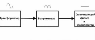
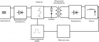
Power supply circuit
The circuit of the most common configuration of a pulse converter includes:
- network noise suppression filter;
- rectifier;
- smoothing filter;
- pulse width converter;
- key transistors;
- high frequency output transformer;
- output rectifiers;
- output individual and group filters.
The purpose of the noise suppression filter is to delay interference from the operation of the device into the power supply network. Switching of powerful semiconductor elements can be accompanied by the creation of short-term pulses in a wide range of frequencies. Therefore, here it is necessary to use elements designed specifically for this purpose as pass-through capacitors of the filter units.
The rectifier is used to convert the input alternating voltage into direct voltage, and the smoothing filter installed next eliminates the ripple of the rectified voltage.
In the case when a DC-DC converter is used, the rectifier and filter become unnecessary, and the input signal, after passing through the noise suppression filter circuits, is fed directly to the pulse-width converter (modulator), abbreviated PWM.
PWM is the most complex part of the switching power supply circuit. His tasks include:
- generation of high-frequency pulses;
- control of the block's output parameters and correction of the pulse sequence in accordance with the feedback signal;
- control and protection against overloads.
Decoupling from the network
It is assumed that the selected power supply provides galvanic isolation from the network. Which of the two types of power supplies will provide maximum isolation? At first glance, the choice is obvious - a transformer power supply, since a switching power supply contains a Y capacitor (or even several) between the input and output.
In theory, a transformer power supply does provide complete isolation from the network, but in practice this is not always the case, especially for toroidal transformers.
In the manufacture of toroidal transformers, the secondary winding is wound on top of the primary and a parasitic capacitor is formed between them. In this case, an alternating mains voltage is applied to the parasitic capacitor. Unfortunately, manufacturers do not standardize the value of the interwinding capacitance of transformers in any way, and it can only be found out by actual measurement “on site”. The general trend is that the higher the power (size) of the transformer, the higher the interwinding capacitance. In addition to the size of the transformer, the value of the interwinding capacitance is affected by the quality of the insulation.
For example, the photo below shows the results of measuring the interwinding capacitance of various toroidal transformers. Capacitance was measured with an RLC meter E7-22 at a frequency of 120 Hz.
In W-shaped transformers, usually the primary and secondary windings are divided into separate sections, so the value of the interwinding capacitance is much less.
Let's return to switching power supplies. The typical value of the capacitance Y of the capacitor between the input and output is 2.2 nF. You can often find a higher value up to 4.7 nF, less often a lower value of 1 nF. Thus, a power supply on a powerful toroidal transformer between the input and output can have a capacity comparable or even greater than in a high-quality switching power supply. At the same time, the presence of capacitance in a switching power supply is known, but this feature of a toroidal transformer is usually not indicated anywhere.
Why is this very container “harmful”? First of all, the parasitic potential at the output relative to ground. This potential can be tens of volts, and if you touch the output of the power supply (or the device powered by it) with a grounded soldering iron or simply with your hand, it will cause the device to fail.
In switching power supplies, to reduce the output potential relative to ground and further reduce interference, capacitors are installed between the output and ground. The recommended total capacitance of capacitors is no more than 20 nF.
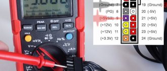
Since the specified capacitors are not installed in all switching power supplies, and the value of the interwinding capacitance for toroidal transformers is not standardized, when using them it is recommended to check for the presence of parasitic potential at the output. To do this, you can use a multimeter in AC voltage measurement mode and, with the power supply turned on, take one probe in your hand (or connect it to ground) and connect the second one to the output of the power supply.
Another negative impact of interwinding capacitance is the penetration of network noise. In this case, switching power supplies are in a more advantageous position because In most cases, they have an input filter installed. This filter prevents interference from entering the network from a switching power supply and vice versa.
Bottom line . When choosing a power supply, if you require maximum isolation from the network, then it is better to use a transformer power supply with a III core and separated windings. It should be taken into account that the W transformer has a larger stray field and can induce interference of 50 Hz. In some particularly sensitive devices, two toroidal transformers are installed in series, which ensures high isolation and low interference of 50 Hz.
Scope of application of a switching power supply
Pulse voltage converters are used in most cases instead of traditional transformers with semiconductor stabilizers. With the same power, inverters are distinguished by smaller overall dimensions and weight, high reliability, and most importantly, higher efficiency and the ability to operate in a wide input voltage range. And with comparable dimensions, the maximum power of the inverter is several times higher.
In such an area as DC voltage conversion, pulsed sources have practically no alternative replacement and are capable of working not only to reduce voltage, but also to generate increased voltage and organize a change in polarity. The high conversion frequency greatly facilitates filtering and stabilization of output parameters.
Electronic transformer
The principle of operation of an electronic transformer is similar to the classical one - when an alternating voltage is applied to the primary winding, an alternating voltage is also removed from its secondary, but of a different value. The difference is that the reduced voltage has a completely different frequency and curve shape, since it is artificially created by a pulse generator.
An example of an electronic transformer circuit and operating principle is shown in the figure below:
Rice. 2. Electronic transformer
As you can see, in it the supply voltage from the 220 V network is not supplied to the transformer windings, but uses a diode bridge as the main converter from a variable electrical quantity to a constant one. The signal is then fed to output transistors, which act as an electronic switch, which generate pulses of a certain number and frequency. It should be noted that the frequency from the pulse generator can reach several tens of kHz, but then it is supplied to a pulse converter, which is represented by a power transformer.
Pulse transformers, or, as they are also called, pulse power supplies, are widely used in powering fluorescent lamps. However, its location in relation to the powered lighting devices should be in close proximity to reduce losses, load in network wires and heating. Compared to a transformer power supply, a pulsed one has a number of significant advantages:
- Smaller dimensions for the same power, which reduces the cost of the device;
- Has the best parameters in adjusting the supplied voltage;
- Features higher efficiency.
But along with the advantages, the pulse unit also has some disadvantages. The electronic transformer has a much more complex circuit, which entails a decrease in reliability. If you go cheap with the transformer model, the output current will release a lot of impulse noise into the network, which can affect the operation of related equipment.
UPS with galvanic isolation
High frequency signals can be sent to a pulse transformer, which is required for galvanic isolation of the circuits. The increased frequency of equipment operation leads to efficient operation and a simultaneous reduction in size and weight. In most cases, devices operate on the basis of 3 chains that must be interconnected:
- PWM controller. This device must control the technological process. In most cases, a pulse width modulation conversion process is assumed.
- Cascade consisting of power switches. This piece of equipment includes power transistors, which can be based on bipolar, IGBT, and field-effect models.
- Pulse transformer. This type of equipment is required for the successful transmission of high-frequency pulses, which can have a frequency of up to one hundred kHz.
Operation of UPSs with galvanic isolation additionally have circuits that are based on stabilizers, filters, and diodes.