Operating principle of RCD, differences from difavtomat
The requirements of the PUE indicate the need to install protective equipment. It provides protection against electric shock and breakdowns of the cable insulation coating. The RCD can be connected to 2 wires in a network with a voltage of 220 V and to 4 wires in a network of 380 V.
The disadvantage of the device is the inability to detect overload or short circuit. An automatic switch will further protect it. The difference between the devices is the response of the RCD to the current imbalance of phase and zero with a nominal value of 10-30 mA. The device does not recognize overcurrents and may even catch fire under their influence.
The difavtomat operates normally at a current of up to 16 A, and turns off the line in case of leaks. Unlike an RCD, it has a time-current characteristic, which determines the speed of shutdown.
A switch with an electromagnetic release trips when the current value exceeds 5-10 times.
PUE Chapter 7.1
Section: Protective Safety Measures
7.1.71. To protect group lines supplying plug sockets for portable electrical appliances, it is recommended to provide residual current devices (RCDs).
7.1.76. It is recommended to use an RCD, which is a single device with a circuit breaker that provides overcurrent protection.
It is not allowed to use RCDs in group lines that do not have overcurrent protection, without an additional device that provides this protection.
When using RCDs that do not have overcurrent protection, their design verification in overcurrent modes is necessary, taking into account the protective characteristics of the higher-level device that provides overcurrent protection.
7.1.79. In group networks feeding plug sockets, an RCD with a rated operating current of no more than 30 mA should be used.
It is allowed to connect several group lines to one RCD through separate circuit breakers (fuses).
Installation of RCDs in lines supplying stationary equipment and lamps, as well as in general lighting networks, is usually not required
7.1.80. In residential buildings, it is recommended to install RCDs on apartment panels; their installation on floor panels is allowed.
7.1.82. It is mandatory to install an RCD with a rated response current of no more than 30 mA for group lines supplying electrical outlets located outdoors and in particularly dangerous and high-risk areas, for example in zone 3 of bathrooms and shower rooms in apartments and hotel rooms.
A comment
The installation of an RCD is mandatory only on street outlet lines, wet rooms and equipment; the connection instructions specify its use (Washing machines, dishwashers, Jacuzzis, etc.). For lighting and regular group lines, installation of an RCD is not mandatory.
7.1.83. The total leakage current of the network, taking into account the connected stationary and portable electrical receivers in normal operation, should not exceed 1/3 of the rated current of the RCD. In the absence of data, the leakage current of electrical receivers should be taken at the rate of 0.4 mA per 1 A of load current, and the network leakage current at the rate of 10 μA per 1 m of phase conductor length.
7.1.84. To increase the level of fire protection during short circuits to grounded parts, when the current value is insufficient to trigger the maximum current protection, at the entrance to an apartment, individual house, etc. It is recommended to install an RCD with a trip current of up to 300 mA.
7.1.85. For residential buildings, when the requirements of clause 7.1.83 are met, the functions of the RCD according to clauses. 7.1.79 and 7.1.84 can be performed by one device with an operating current of no more than 30 mA.
Features of integrated operation of protective devices
Protective devices must be installed strictly according to the diagram
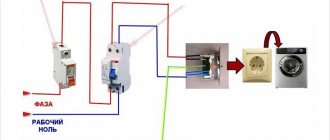
. To understand how to install an RCD - after or before the machine, you need to understand the functionality of the installation. A good example would be a system consisting of a metering device, a residual current device, or a circuit breaker connected to one line.
The voltage from the transformer will pass through the RCD and the meter, supplied to the sockets. If there is no protection, the shutdown device burns out. The absence of a release in front of the meter will also lead to a line fire. The best option is a protective device on both sides.
According to the requirements of the PUE, two-pole modifications of machines are placed before the metering device. There is no need to place it in front of it - it is better to protect the line from the RCD to the consumers.
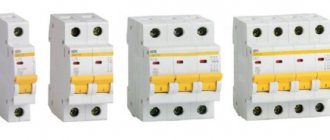
How to choose: what the labeling tells you
Before learning how to calculate the performance of fire fighting equipment, it is important to choose the right device with ideal technical characteristics.
They will be indicated by markings on the body. The following information must be indicated on the device: The following information must be indicated on the device:
- manufacturer, brand;
- series or product number;
- voltage in nominal designation;
- operating frequency;
- operating current;
- indicator at which the device will operate;
- the highest values for turning on and off;
- protection;
- the position in which the device should be located;
- installation diagram;
- performance indicators for normal functioning.
These are the main indicators that any high-quality equipment must have, be it a fire protection RCD or for a water heater.
The device must have a passport indicating the license, certification, verification and its compliance with state quality standards. The use of units that do not have such documents is strictly not recommended for safety reasons.
The RCD passport must contain complete information about the unit
Installing an RCD before or after the machine
The device responsible for disconnecting the line does not respond to overcurrents, therefore it does not operate in the event of short circuits and overloads. A joint connection with a difavtomat will prevent these situations.
Since the circuit current exceeds the rated current, the internal components of the device are damaged and the contacts burn out. Models without built-in protective elements must be installed together with circuit breakers that will eliminate the effects of overloads and short circuits. In this case, the current of the circuit breaker should not exceed the current rating of the RCD. For example, the latter reacts to 40 A. The optimal switch for it is 36 A.
Connection diagrams for RCD with switch
Protective equipment must be connected using two cables. The first will carry the load current, the second will be directed to the external circuit from the consumers. In order not to think about installing an RCD before or after the machine, you should use popular schemes.
For several groups of difavtomats - one RCD
Clause 7.1.79 of the PUE allows for the protection of several lines using an RCD. The device needs to be placed on top, then the switches on the consumer groups. In case of short circuits, the current passes through the RCD to the group circuit breaker, then to the power cable and to the consumer. If the rating of the devices is selected correctly, none of them will be damaged.
The advantages of implementing the scheme include saving money and space in the distribution panel. The downside of the connection is that all groups are disconnected after the RCD is triggered.
Installation of RCD to the machine
RCD in front of the machine
The scheme provides for installation in the following sequence:
- Safety shutdown device.
- Difavtomat.
- Power cord.
- Consumer.
If there is damage, the short circuit current passes through the RCD until the circuit breaker stops.
RCD after the machine
RCD after the machine
Assembly of the system is carried out according to the principle;
- switch - two-pole or feeder;
- counter;
- RCD;
- machines depending on the number of lines.
This option is correct, since it is easy to understand how to turn off the machine and apply input to its terminals. Despite the fact that RCDs break more often, they are easier to replace.
At the moment of a short circuit, the current will pass from the switch to the RCD, then to the power wire, then to the consumer. The switch stops and the protective device remains intact.
To prevent overload, a second automatic circuit breaker can be installed between the meter and the RCD.
Connecting an RCD to a group of machines
Connecting an RCD to a group of automatic machines
A similar circuit is assembled in a three-phase switchboard, where the following are located:
- 3 three-phase difavtomat;
- three-phase RCD;
- 2 single-phase RCDs;
- 4 single-phase single-pole circuit breakers.
From the first input circuit breaker, the voltage will go to the second three-phase circuit through the upper terminals. From the same device, one phase will go to a single-phase RCD, the second to the next one.
Single-phase protection devices have two poles, difautomatic devices have one. In order for the system to work without failures, it is necessary not to connect the working zero after it. For this reason, a zero bus must be installed after each protective device.
If there are two-pole circuit breakers, a separate zero bus is not installed. When two zeros are combined, a false positive may occur.
The first single-pole RCD is connected to differential circuit breakers No. 1 and No. 3, the second - to No. 2 and No. 4. The load is applied to the lower terminals.
The grounding bus is common, but it must be installed separately. Three phases with a working zero are connected to the input device. It is connected to the common zero, and then diverted to all RCDs. After device No. 1 it goes to a three-phase load, after the remaining single-phase loads - to each bus.
The wire into PEN and PE is not separated - ground, zero and 3 phases go to the shield.
Common mistakes made by experts
Sometimes even electricians with extensive experience make some mistakes when connecting machines and RCDs. In order to avoid negative consequences, it is necessary to consider them in more detail.
Table 2. Errors during installation.
| Error, illustration | Description |
| Connecting cores without termination | This is one of the common mistakes that craftsmen make when in a hurry, because this way it can be easier to connect the wiring. However, this does not allow the ends to be fully clamped, so after a short period of time the contacts will become weak. At the same time, they will begin to overheat, so they attach tips to the ends of the wires or squeeze them tightly. |
| Contact of the insulating layer | As we discussed in the previous instructions, first the wire must be stripped of the insulating layer to the required length, and only then placed in the clamp and tightened with a screw. However, some users experience sudden burnout of the machine or intermittent operation when new mechanisms are installed. A common cause of the problem is precisely the insulation getting under the contact of the machine. This leads to the fact that after connecting the protective layer, the wiring begins to heat up. Over time, it may catch fire, causing a fire in the panel. |
| Different thicknesses of cores in one clamp | Automatic switches should not be combined with jumper wires of different thicknesses - this will lead to the fact that when tightening the screw, only the large core will be securely fixed, and the small one will have weak contact. Due to such negligence of electricians, fires often occur that affect the insulation and switchboard circuit breakers. The photo shows a clear example of connecting machines with wires with a thickness of 4 square millimeters and 2.5 square millimeters. This led to the fact that after overheating, the wiring and body of the machine melted. Even if you take wires with a minimal difference in thickness (1.5 and 2.5 square millimeters), you should not expect other consequences, because they still cannot be tightly connected in the clamp. |
| Soldering the ends of the cores | Some craftsmen, due to a lack of skills, prefer to use an unsafe method of terminating cores - soldering. They do this because they save money on the purchase of special devices. In addition, electricians prefer to use this method for urgent installation. However, the use of this method is prohibited. After all, the contact is less easily fixed by the clamp and begins to weaken over time, so it will have to be constantly tightened. In practice, such actions are quickly forgotten. What causes a fire to occur. |
Where should the RCD be installed?
To determine where to install the residual current device, you need to remember the speed of current flow through the wires. It is equal to the speed of light - 300 thousand km/sec. In a standard C 16 machine, the turn-on time when passing currents of 5×In (80 A) will be 0.02 seconds. The distance it will cover is 6000 km.
In the event of a short circuit, the current will completely pass through the coupling device - RCD - cable - socket. In this case, the switch does not operate instantly, as a result of which the insulation melts and the socket contacts burn out.
The RCD does not fail, since a short circuit is an inertial reaction. A time of 0.02 seconds is simply not enough to melt the insulating coating and damage the parts. Even taking into account the breaking capacity, the protective devices will work properly regardless of the installation location:
Protective devices will work properly regardless of the installation location
- Automatic - RCD. The phase is supplied using a jumper, and the zero is supplied directly to the protective device. The wire for the sockets is connected to the device and the PE bus.
- RCD - automatic. The wire is connected to the sockets through different paths. The phase one goes to the machine, the zero goes to the protection device or the zero bus.
Thus, there is no difference where the RCD was installed - before or after the automatic device.
Examples of connection errors
Errors when installing an RCD can negate all its useful functions. The most common mistakes are:
- connection of neutral and grounding after RCD;
- half-phase connection;
- connection of the neutral and grounding conductors in the socket;
- connecting two RCDs with combining zeros;
- incorrect connection of neutral wires (connection of several RCDs);
- incorrect connection of phase and neutral (phase and neutral from different RCDs);
- non-compliance with connection polarity;
- incorrect connection of a three-phase RCD.
Let's take a closer look at each of these errors.
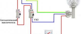
Connection of neutral and grounding after RCD
It is strictly forbidden to ground the neutral wire. Such a connection is similar to the situation of a circuit breakdown, when current from the body of an electrical appliance flows into the ground. Naturally, in this case, the protective shutdown device will constantly start to operate and de-energize the object. After such false alarms, it will be necessary to completely check the circuit and eliminate the situation of a real breakdown.
Single-phase connection
If the neutral wire is first connected to the load and then to the RCD, then the currents of the phase and neutral wires will be different and an unjustified operation of the mechanism will occur.
Connection of the neutral and grounding conductor in the socket
If in a socket protected by an RCD the neutral conductor (N) and grounding (PE) are connected, then when any electrical appliance is plugged into the socket, a false operation and network shutdown may occur. The same can happen if a load is turned on in the same system, but outside the service area of the RCD. In this case, the differential current can flow through the jumper connecting N and PE in the socket.
Connecting two RCDs with combining zeros
If in the protection zone the zeros of devices protected by one RCD are connected to the zeros of devices served by another RCD, then tripping in one of the groups will lead to the shutdown of the other group, although there are no emergency situations in it. Accordingly, searching for the location of the breakdown will take much more time.
Incorrect connection of neutral wires (connection of several RCDs)
The zero of one RCD goes to the group protected by another RCD, and the zero of the second goes to the first group. Thus, the phase wire of each protective device is connected to its own group, and the zero wire to the adjacent one. Therefore, if there is a breakdown in one of the groups, both RCDs are switched off at once. It is impossible to establish an incorrect connection by testing devices: the test procedures proceed normally.
Incorrect connection of phase and neutral (phase and neutral from different RCDs)
In this case, the phase goes through one protective device, and the zero through another. At a minimum, such a connection is redundant - after all, there are two RCDs per group of devices. In addition, as a result of such a connection, two RCDs may be triggered, or maybe only one. If the trip does not occur on the “phase” RCD, then the person will not be protected from breakdown.
Incorrect connection polarity
If you connect the phase at the top and the zero at the bottom, then the magnetic fluxes that arise in the differential transformer will not destroy each other. As a result, an instantaneous trip will occur and the RCD will turn off the network.
Incorrect connection of three-phase RCD
Errors in the use of four-pole RCDs in a three-phase circuit are mainly due to the fact that the same phases are connected to the terminals of the device. Moreover, if the energy consumers are single-phase, then this does not create any problems. But where three-phase devices operate with a voltage of 380 volts, such an error is unacceptable.
The video talks about RCD connection errors. Filmed by EKF channel.
Machine denomination
Table of ratings of circuit breakers
On the body of any device, the rated value is indicated - the value of the maximum continuous current that passes through the device without harm. This parameter is safe for current switching.
To ensure protection of the RCD itself, it is necessary to install a circuit breaker with a rating similar to or 1 more than the rating of the device. If you have a machine with a rating of 16 A, the RCD should be about 25 A. This current reserve will be enough to prevent the flow of energy when the load increases.
The machine is triggered when a current appears 13% higher than the nominal value: a 16 A modification will operate at a current of 18 A. If the RCD rating is equal, the contacts may heat up. To select the rating of a system with several circuit breakers, you need to sum them up and select an RCD with a larger rating.
The nuances of installing a protective device
Connecting an RCD and a breaker in a single-phase TN-C system
Connecting an RCD in an apartment or house requires compliance with several rules:
- For several groups of consumers it is necessary to install one RCD and individual circuit breakers.
- If there are several RCDs, each of them will need a zero output bus.
- The TN-C system does not need to be zeroed.
- For “wet groups” it is mandatory to install a protective device with a shutdown rating of 10 mA.
- 30 mA devices are suitable for household appliance outlets that operate with water.
- The zero terminal is located on the right side of the device and is marked with the letter N. It should not be confused with the phase (index L).
- Input can be made to the lower or upper terminals.
- The classic circuit is implemented using a top input and a bottom output.
- Each RCD requires a personal zero block to which all working neutrals are connected.
- For lines with ripple currents, type A devices are required.
You can check the health of the system by pressing the “Test” button.
A protective shutdown device is needed to protect against overloads and short circuits. Due to the lack of response to overcurrents, it is installed in combination with a difavtomat. Connection diagrams allow installation of devices in any order. The only condition is the choice of the appropriate denomination.