Hello readers of my blog! Today we will talk about how to properly install a manifold for a heated floor with your own hands. It would seem that the matter is not tricky, but when you are faced with this problem, you have to think about how to do it correctly, what preparation to do, what materials to choose. Thus, I decided that this article would be useful to someone, and I am devoting my efforts to this subject. In it I will answer a number of questions that will arise immediately before How to properly install a manifold for a heated floor with your own hands, and some even after that. This topic is quite broad, because before work, thorough preparation is necessary, but how to do this? And this is a separate topic. You can learn about all this in great detail in the article below. How to properly install a manifold for a heated floor
Traditional radiators, for many years considered the only possible source of heat, are gradually giving way to systems of warm floors and ceilings. Many people experience innovative methods and are very satisfied. However, heated floors can hardly be called an innovation.
They have proven themselves well and become a fairly common heating method.
Such systems can run on electricity or use hot water energy.
According to experts, a water heated floor is considered the most effective and practical to assemble with your own hands, but it is quite possible to assemble it if desired.
Unit #1 - water heating boiler
The boiler selected for installation must have sufficient power to cope with the heating of the coolant during peak operation of the circuits. In addition, it should have a small power reserve.
Approximately, this value should be the total power of all maintained heated floors, increased by 15-20%. In addition, a circulation pump is needed. Most often, it is already included in most boiler models.
An additional device may be needed only if the area of the heated room is more than 120-150 square meters. m. In case of preventive maintenance or repair of the boiler without draining water from the entire system, shut-off valves are installed at the outlet and inlet of the heating device.
Unit #2 - collector
The collector is a device responsible for distributing hot water through heating circuits, as well as setting up and adjusting heated floors. The device must have a sufficient number of terminals to connect all circuits to them.
The simplest models are equipped only with shut-off valves. They are extremely cheap, but do not provide even a minimal opportunity to customize the system.
Devices with control valves allow you to adjust the water flow for each circuit, which allows you to adjust the heated floor for the most uniform heating of the premises.
The manifold of any model must be equipped with a drain outlet and a special air vent valve. The most convenient to use are devices with servo drives on valves, equipped with pre-mixers that mix the heated water supplied to the system with the cooled water returning and thereby regulate its temperature.
Such a device fully automates the functioning of a heated floor, but its cost is very high.
Manifold with servomotors on valves and pre-mixer. Necessary system adjustments are made automatically
Video description
The capabilities of the collector, its configuration and operation are shown in the video:
Adjusting the supply of working medium
Flow meters (rotameters) make it possible to ensure uniform heating of loops regardless of their length, even if circuits that differ markedly in length and hydraulic resistance are connected to the comb.
For short pipelines, the fluid supply is regulated by reducing the passage opening; for long branches, on the contrary, the flow intensity is increased. This parameter is determined on the scale of the balancing rotameter for each circuit, after which the throughput of the flow valve is adjusted.
Adjustable flow meters are installed on the feed manifold only if it is equipped with manual valves for adjustment. They are not necessary if:
- branches of the same length are connected to the collector, and regulation of distributed flows is not provided;
- the collector block is equipped with automatic control valves with servo drives - in this case, the automation is controlled by an electronic thermostat and manual equalization of the heating of the branches is not required.
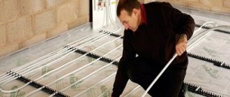
How can water floors be installed?
Warm water floors can be laid in different ways - by laying and using concreting. Let's take a closer look at each of them.
- Concreting. The pipes through which the coolant circulates are laid as required on the prepared base and filled with concrete screed. The main disadvantages: labor-intensive “wet” work, the heavy weight of the system and the complexity of its dismantling.
- Laying method. Involves laying pipes in a specially assembled deck.
It can consist of plastic modules or wooden blocks with grooves prepared in them for installing pipes. Wooden mounting modules can also be found on sale. The main disadvantage is that the system takes longer to warm up than a concrete one.
What needs to be done before installation?
Proper installation of a warm water floor requires careful preparatory work. During their course, all the little things must be taken into account, on which the effective functioning of the structure will subsequently depend:
It is best to entrust the design of the future system to specialists, since it is quite difficult to make independent calculations.
It will be necessary to determine the length of the pipe, the pitch of its installation and the power of the heating circuit, if there are several of them, then for each separately. In this case, many nuances and parameters are taken into account. There are special calculation programs that many people use.
However, you need to understand that a flaw in the calculations will lead to a decrease in efficiency or simply the impossibility of functioning of the entire system. Equipment for heated floors must be of high quality, manufactured and purchased from a reliable company that offers good guarantees.
It will be cheaper to pay for a quality product than to subsequently constantly shell out decent sums for expensive and labor-intensive repairs. To minimize the thermal load on the screed and prevent it from cracking, the system should be divided into sections of no more than 40 square meters. m. The base for heated floors must be carefully prepared.
It must be clean and level, differences of more than 5 mm are not allowed. To prevent heat loss, a heat-insulating layer must be spread on the prepared base, with a height of 3 to 15 cm, depending on the operating temperature of the coolant. This could be special heat-insulating materials or mats designed for warm water floors. The latter can be equipped with pipe mounts, so-called bosses, which is very convenient.
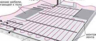
A damper tape is laid around the perimeter of the room and between the installation areas, which can compensate for temperature fluctuations of the screed.
Mats with bosses designed for water heated floors are very comfortable. They not only act as a heat insulator, but also secure the pipes in place
When drawing up a laying scheme, you need to avoid a large number of pipe joints, which carry the potential danger of leaks under the floor. It is best to arrange the safest option, where connections are present only at the outlet and inlet of the collector. In this case, the length of the solid pipe should not be more than 90 m, otherwise the temperature of the circulating coolant may drop.
Preparing the base
The primary task when preparing the base for the floor is to remove the old screed, regardless of its type. When the old screed is removed, you need to start leveling the base level. The base for a heated floor must be strictly horizontal - height differences of no more than 1 cm are allowed over the entire area of the base.
The horizontal surface is covered with waterproofing material, and it must be laid hermetically and with a small tolerance along all edges. A special tape is attached along the perimeter of the walls at floor level, which is necessary to compensate for the thermal expansion of the floor during heating operation. If the underfloor heating system includes several separate circuits, then there must be the same tape between them.
Laying a heated water floor in a screed
Work begins with determining the installation location of the collector, which is most often “hidden” in a special cabinet. It is usually mounted on the wall.
The device should be placed so that the length of pipes from each of the heated rooms is approximately the same. You can bring the collector closer to the largest contours.
The main thing is that it is installed above the level of the heated floor, without venting pipes upward, otherwise there may be problems in the air exhaust system.
The next stage is marking the prepared base, taking into account the division into sectors of 40 square meters. m. Then a thermal insulation layer and damper tape are laid.
Next, the reinforcing mesh is laid on which the pipes will subsequently be attached. If special mats are chosen as thermal insulation, the mesh will not be needed. You can start laying out the pipeline.
It can be done in different ways: snake, spiral, loops, etc. The laying step varies from 10 to 40 cm, and the distance from the wall to the nearest pipe cannot be less than 8 cm.
The pipes are secured to the reinforcing mesh using plastic clamps.
It is important not to pinch the part; it should be in a loose loop, otherwise, under the influence of heat, the pipe will expand and may become deformed in the area of tight pressing. The fastening clamps are installed in 1 m increments. You must work with the pipe very carefully.
Most often it is supplied in the form of a coil. Pulling it out from there one by one is unacceptable. You should gradually, as it is laid, unwind the pipe, placing and securing the element on the floor.
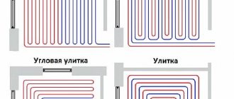
There are several options for laying pipes for heated floors. The most common:
- spiral,
- snake,
- loops,
- double snail
Rotations of the part are performed very carefully, observing the minimum bend radius requirements. Typically it is about five pipe diameters. If you squeeze the product, a whitish crease area will form.
It indicates a sharp stretching of the fragment and loss of its strength characteristics, which leads to an increased risk of pipe rupture. It is not recommended to install a part with such a defect in a heated floor system. The damaged fragment must be replaced, which leads to the appearance of unnecessary joints in the pipeline, and this is also undesirable.
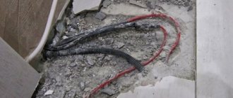
The laid pipes must be connected to the collector. For this purpose, special compression fittings or Eurocone systems are used.
The beginning of the pipe of each heating circuit is connected to the supply outlet of the manifold, thus the number of outlets and circuits must match. The end of the pipeline is connected to the return manifold. If the pipe is laid near an expansion joint, a corrugated tube must be put on it.
Upon completion of installation, the system must be checked.
To do this, water is poured into the pipeline and a pressure of 5-6 bar is applied throughout the day. After which a careful inspection is carried out to identify possible expansions on the pipes or leaks. More details in the video:
If the test run was successful, proceed to pouring the screed.
It should only be carried out with pipes filled with water and operating pressure in them. After pouring, the screed will dry completely no earlier than after 28 days. After this time, you can begin work on installing the flooring.
Before you start pouring the screed, the pipes are attached to the reinforcing mesh using special plastic clamps that prevent the elements from moving
There are some nuances regarding the formation of screeds over water-heated floors. They depend on the type of flooring that will be laid on top of it. If you plan to install tiles, the screed should be 3-5 cm high or the distribution of pipes should have intervals of about 10-15 cm.
Otherwise, according to the principle of heat distribution, there is a danger of the appearance of a “thermal zebra”, which can be clearly felt by the foot. But under laminate or linoleum it is better to lay a thinner screed. In this case, in order to strengthen the structure, another reinforcing mesh is laid on top of the heated floor, which will also reduce the thermal path to the surface of the coating.
You can find many recommendations on how to make warm water floors yourself.
However, you need to clearly understand that this is a complex and responsible undertaking. A pipeline laid in a screed is practically beyond repair, and if installation or design errors are discovered at this stage, it will be extremely difficult to correct them. That is why the work should be approached very responsibly, then the new heated floor will only delight you with its long and effective operation.
How to properly assemble a manifold for a heated floor
When the installation of water floor heating circuits is successfully completed, before pouring the screed, it is necessary to connect the underfloor heating pipes to the collector. This is done in order to check the tightness of the circuits and identify manufacturing defects or possible pipe defects that may arise during the installation process.
The operation of testing the pipelines must be carried out, otherwise in the event of an accident after starting the heating, the floor covering will have to be destroyed.
After the screed has been completed and the solution has hardened, it is connected to the main pipelines and the system is put into operation. How to properly assemble a manifold for a heated floor and combine it with a mixing unit will be discussed in this material.
Connection rules
In most cases, a ready-made manifold is purchased, in which all elements are selected according to technical characteristics. If you have experience in assembling such structures, you can assemble the device yourself. How to properly connect a heated floor, take into account the parameters of the overall heating system and the technical properties of the combs? To do this, you must follow certain installation rules.
Attention: First, a general connection diagram is drawn up, which indicates the dimensions of the pipes, where they are laid and connections to the heating. The throughput capacity of each comb must be calculated, their diameter and material of manufacture must be selected. The most commonly used products are stainless steel or copper.
The location of the device is selected based on the following rules:
- The highways should be approximately equal in length.
- The section of the wall where the manifold cabinet for heated floors will be installed must have free access. Furniture or other parts of the interior do not interfere with a full inspection of the device or carrying out preventive or repair work.
- The connection point of the device must be higher than other elements of the system.
A security system must be installed. It consists of an air valve and a bypass. When the temperature of water rises sharply, it expands. The air valve releases excess air, normalizing the pressure in the pipes. A bypass is necessary to quickly shut off water in case of emergency situations.
Once the installation of the collector is complete, the underfloor heating pipelines are connected to it. The quality of the joints, their tightness and reliability must be checked. The system is started before the main covering is installed. By changing the temperature conditions using the control device, the heating quality of each line is checked, and the pipes are inspected for leaks. After this, you can begin installing the flooring.
The role of the collector in underfloor heating systems
The collector is an element that underfloor heating cannot do without; all pipelines from the heating circuits are connected to it. Since the temperature of the coolant supplied to the network from the boiler room is too high for the operation of heated floors, a mixing unit always operates together with the collector, ensuring the water temperature is within 40-45 ºС.
Mixing units and manifolds for heated floors perform the task of preparing the coolant at the required temperature and supplying it to all circuits.
To understand how the entire assembly works, let’s look at the collector device in more detail. It consists of two horizontal tubes connected to the supply and return lines. The manifold body and parts are made of the following materials:
On the supply tube there are branches with thermostatic valves (actuators), and on the return there are branches with flow sensors. There are plastic caps on top of the thermostats for manual adjustment; twisting them leads to pressing on the rod and blocking the flow. Flow meters or flow sensors located on the return pipe of the manifold for a warm water floor serve to visually monitor the amount of water flowing and perform hydraulic balancing of the system.
The cheapest versions of collectors may not have flow sensors.
In order to control pressure and temperature, a thermometer with a pressure gauge is installed on the manifold, and a special valve is installed to bleed air. The kit also includes plugs, bends, taps and brackets for attaching the unit to the wall or to the metal slats of the cabinet. Many suppliers practice a complete set of the entire assembly, where there is a distribution manifold assembled with a pump and a two-way or three-way valve.
Mixing valves
Depending on the desired effect, there are various connection methods. Each of them necessarily involves the installation of mixing valves. These devices are necessary to connect hot and cold water. The latter is supplied from the heating circuit, the former from the boiler. The system can be adjusted automatically or manually, which requires additional installation of a control servo drive. There are two types of mixing valves.
Two way servo
This servo is also called the feed servo. Its main difference from conventional valves is the ability to conduct water in only one direction. If the valve is reinstalled incorrectly, it begins to malfunction and quickly fails.
“Feeding” – conducts water in one direction only
A ball or a special rod is used as a locking part for it. Adjustment is made either by turning the ball or moving the rod. Electric drives are used to carry out these manipulations.
The most popular method is a thermostatic head equipped with a water sensor that regularly monitors the temperature of the coolant. Taking into account the received data, the head turns the valve on or off. So, coolant is supplied from the return line regularly, and from the boiler - only as needed.
The operating principle of the device explains the main advantage of the manifold, which is equipped with a supply valve. Floors with this equipment do not overheat, this significantly increases their service life. The low throughput of the valve creates a smooth adjustment of the coolant temperature; significant jumps in this case are excluded.
Supply valves are characterized by ease of installation and subsequent operation. They are quite often found in the circuit of homemade manifolds for heated floors, but they have some limitations in application. It is not recommended to install two-way devices in systems that operate in rooms larger than 250 square meters.
Three-way systems
Three-way elements are designed differently. This equipment combines the operation of a bypass supply valve and a bypass valve. The valve consists of a body with one supply and two outlets. For regulation, either a rotating ball or a special rod is used.
The peculiarity of this type of device is that the adjusting part completely blocks the flow and distributes the incoming water, mixing it. The temperature is adjusted automatically; for this, the valve has a drive system that receives signals from various sensors.
Such valves have servo drives
Typically, three-way valves are equipped with actuators that are controlled by thermostatic sensors or weather-compensated controllers. The servo drive activates the locking mechanism, which is installed in the required position to obtain the required indicator of the heated coolant and return.
Weather-dependent controllers are required to regulate system power based on the weather. For example, during a cold snap, the room will begin to cool down much faster, meaning it will be much more difficult for the heating system to do its job.
To make the task easier, you need to increase the consumption of coolant and increase the temperature. The main disadvantages of three-way elements include significant throughput. Under these conditions, even a slight shift in adjustment can lead to a sharp change in water temperature.
Three-way elements are used for manifolds installed in rooms larger than 250 square meters. m and systems with a large number of circuits. Moreover, they are used for structures that are equipped with weather-sensitive sensors that determine the required floor temperature taking into account atmospheric conditions.
Operating principle
The unit works like this: the coolant circulates through all underfloor heating circuits, driven by a pump.
The flow rate in each circuit is controlled by a valve manually or automatically, by a capillary or servo drive. When the temperature in the supply or return pipeline (depending on the circuit) drops below the set value, a two- or three-way valve begins to mix hot water from the system, and the coolant from the return flows into the general network. The figure shows a diagram of the operation of a manifold with an attached water temperature sensor and a two-way valve:
There are several operating schemes for the mixing unit, they use different parts, but its task remains the same: to maintain the required temperature in the underfloor heating system and control the coolant flow in the supply branches.
Design and principle of operation of servomotors
The main working element of the servo drive is the bellows. Those. same detail as in . A small, sealed cylinder with an elastic body is filled with a substance that is sensitive to temperature. Depending on whether the temperature increases or decreases, the volume of the substance changes accordingly. The figure - diagram clearly demonstrates the structure of the servomotor, where the bellows occupies the main place.
The bellows is in close contact with the electric heating element. Receiving a signal from the thermostat, the heating element is switched on from the mains and starts working. Inside the bellows, the substance is heated and increases in volume. Thus, the cylinder, which has increased in size, begins to put pressure on the rod, changing its position and blocking the path of coolant flow. Evaluating the operation of the servo drive, we can conclude that the device is not equipped with any motors, it does not have any gears or transmission links. The usual working connection is “thermal energy and electricity”. Hence the common name for the devices, thermoelectric regulators.
In order for the valve to become open again, the entire process is repeated only in the opposite direction. Lack of power causes the heating element to stop working. Consequently, the substance inside the cylinder cools, decreasing in volume. The pressure on the rod decreases, it rises, acting on the valve, and, consequently, hot water access to the system opens.
Having become familiar with the principle of operation of the device, it is important to remember that the mechanical action of the valve requires a certain time. Despite the fact that when a signal is received from the thermostat, the heating element begins to heat the substance inside the cylinder. The time required for changes in the physical state of the liquid is 2-3 minutes, so the valve is not activated immediately
Unlike heating, cooling of a liquid occurs more slowly. To the reverse process, i.e. Closing the valve will no longer take 2-3 minutes, but 10-15 minutes. If overheated, each servomotor should automatically turn off. For this purpose, the design provides an emergency shutdown mechanism.
For example: the servos used in the operation of the collector group are not all equipped with cylinders and cylinders with a substance. There are models in which this role is played by thermocouples, resembling a spring or plate, which heat up under the influence of the same heating element. Expanding, these parts again act on the rod, ultimately bringing the valve into working condition. You can determine what position the valve is in by changing the appearance of the servomotor. The retractable element signals the operation of the device. If this does not happen, it means that your device is not connected correctly or the heating system is not working properly.
Recommendations for manifold assembly
It is not difficult to assemble the underfloor heating manifold, supplied as a complete set.
The tubes for the supply and return coolant are already equipped with valves and flow sensors; they only need to be twisted together if the manifold included is divided into sections of 2 or 3 branches. Then, for the convenience of further assembly, it is better to fix the tubes on standard brackets, then the distributor will be a single unit. Then plugs, connection elements, shut-off valves and control devices are installed.
The delivery set of each product includes instructions, with its help you should assemble and install the underfloor heating manifold.
The next step is to attach the collector to the wall, and after that you can install the circulation pump and valve.
There is no point in doing this in reverse order; then it will be inconvenient to attach the entire assembly. The pump and valve with a thermal head or servo drive are mounted in accordance with the selected diagram, after which the main heating pipes coming from the boiler are connected to them, and pipes from the heating circuits are connected to the outlets. There are situations when the distributor is installed not in the boiler room, but in a corridor or other room, then for installation it is better to use a decorative cabinet for the manifold.
Since the cost of a factory-made manifold is quite high, such a unit can be made independently. True, you will still have to purchase a pump and valve for the mixing part, as well as shut-off valves. The most popular way to assemble a homemade manifold is to solder it from polypropylene pipes and fittings.
This will require sections of PPR pipe with a diameter of 25 or 32 mm, tees and bends of the same size and valves. The number of fittings and valves depends on the number of heating circuits. Tools you will need are a soldering iron for polypropylene pipes with nozzles, scissors and a tape measure.
Before making a polypropylene manifold, you need to measure and cut sections of the pipe so that after connecting the tees are as close to each other as possible, otherwise the assembly will not look aesthetically pleasing.
Then taps and transitions are welded to the tees, and the remaining fittings for connection to the pump are welded to the resulting manifold.
It should be noted that a homemade manifold for heated floors, made with your own hands, will have some disadvantages.
For example, there are no thermostatic valves on the branches in the supply line, and there are no flow sensors on the return line. In their absence, the system will have to be adjusted manually, and this does not always give good results. Of course, all these elements can be installed and connected separately, but then the labor costs will be such that it is easier to purchase a finished product made of plastic, whose cost is quite affordable.
Despite the apparent complexity of the mixing and distribution unit, assembling it is not that difficult. The product usually comes with detailed instructions and should be followed. It is more difficult to make a distributor with your own hands, but this is always advisable, since you still need to buy components, and there will also be difficulties in setting up the manifold.
DIY collector
Warm floors have long been a sign of high-standard rooms.
Their use is due to the high quality of heating - the room is heated throughout the entire volume due to natural convection, since the entire floor area serves as a heater for the air in the room.
The floor itself is heated by an electric, film or good old water heater - a hot water boiler.
Distributor made of metal fittings
If you use metal fittings instead of polypropylene, you will be able to slightly reduce the size of the structure and do without a soldering iron. But here another pitfall awaits you in the form of cheap thin-walled tees, which are scary to handle with a pipe wrench - low-quality material can crack. If you buy high-quality fittings, then the total price of the product will be closer to the factory manifold, although the savings will still remain.
For manufacturing, you need to select internal/external thread tees made of good brass, shown in the photo, and ball valves with a low stem and a butterfly handle. The same radiator valves will go to the second part of the comb. The assembly technology is simple: pack the threads with flax or thread and twist the fittings together, and then install the taps and other parts.
Advice. When assembling, try to direct all the side bends in one direction, as well as the valve stems, so that the homemade manifold looks presentable. When screwing on pipeline fittings, remove the handles and adjusting caps so that they do not cling to adjacent taps.
Installing flow meters on a comb of brass fittings is a difficult issue. Then the supply line will have to be assembled from crosspieces and special adapters for rotameters will be installed. Some of them are also made for Eurocone, so the adapter will have to be machined. It is easier to balance the system without flow meters.
As you can see in the photo, there is nowhere to put the rotameter here
Function performed
A residential building or apartment has several rooms, and in each of them a thermal circuit is laid in the floor.
It is connected to the coolant main through an input-output unit in the form of two pipes.
The need for thermal energy for each circuit is usually different: the temperature in different rooms may differ. On the other hand, the areas of the rooms are not the same, which means the volume of coolant for each room is also different.
Thus, a distributor with regulator functions must be installed between the boiler and the heating circuits. Such a device is called a collector. In terms of its functionality, it is a mixing unit. Its task is to ensure the supply of water to the circuits.
Specialist's note: the inlet temperature from the boiler can reach 80 degrees, and for a heated floor circuit, according to the standards, the water temperature should not exceed 40 degrees.
You can achieve the required value, i.e. reduce it to 40C, by mixing hot water with cooled return water.
Typically, the collector pipe has connecting nodes - according to the number of thermal circuits.
In total, the collector contains two pipes:
Hot water from the boiler is added to the mixer by turning on a thermostatic valve, which is placed in the path of water supply to the mixer. When the temperature in the mixer drops below the permissible level (we remember - this is 40°C), the valve supplies a portion of hot water.
Please note: a thermostat is installed at each outlet of the mixer comb to limit the volume of hot water for each heated floor circuit.
This group of bimetallic valves changes the flow area, as well as the volume of water passed through.
This allows you to set the temperature as desired. Flow sensors are installed at the return inlets, and the return comb is also equipped with an air vent. The coolant is pumped through the system using a water pump, which creates the necessary pressure in the line.
A complete set of manifold parts also contains various plumbing fittings. In the set of devices for warm water floors, the collector is perhaps the most important of them, as it provides:
Tips from the professionals
When installing this device, you should pay attention to the following recommendations:
Dimensions of a wall-mounted cabinet for a manifold unit
- the thickness of the collector box must correspond to the dimensions of the unit;
- You must remember to leave free space for bending pipes from each installed circuit. It must be provided directly under the block;
- The device box is placed at a point that is at the same distance from all contours.
If you use a ready-made collector group, you can significantly simplify the installation of this device. It is very easy to install it yourself without the help of specialists.
Homemade designs
The collector has a significant drawback - high cost.
Therefore, many “homemade” people assemble various options for collectors with their own hands, depending on their wallet and the availability of components.
There are two options for this path:
The 3-loop collector circuit can be implemented as follows:
First, you should assemble the collector pipes - return and coolant supplying the heating circuits. To do this, use one comb for 3 channels or 3 single-loop units for each manifold. The return manifold is equipped with a flow sensor or flow meter and a counter-mounted connection unit for return supply hoses along each loop.
Single-loop manifolds are connected by threaded elements into a comb. Each coolant loop contains a heat sensor with an actuator and a connection point for the power line of the thermal circuit. Air vents are connected to one end of the collectors, and at the other, a coolant pump is connected to the collector pipes, and in addition a thermostatic valve or servo drive is connected to this point, which from time to time replenishes the mixer with hot water. The collector assembly is attached to the wall, checked for functionality and connected to the thermal circuits. After this, final installation and configuration of the entire system is carried out.
Here is the simplest working version of a manifold for heated floors, available to a wide range of DIYers. The capabilities of real collectors are often expanded by connecting more complex control and metering systems.
For example, they connect heat meters, additional temperature meters and much more, no matter what - that’s why homemade inventors exist, to “assemble something yourself.”
If a homemade manifold is soldered from polypropylene pipes, then you need to replenish your arsenal of tools with a special soldering iron for welding parts made of this polymer.
When assembled by welding, the size of each single-loop unit increases due to the seams, and if there are more than 3 thermal circuits, then the entire collector becomes bulky and its installation becomes problematic. Otherwise, the design of the plastic manifold and its settings are no different from those described earlier.
Well, now it's time to finish the article. All the material I wanted to share has been reviewed. I hope it will be useful to you, and you will use it if you need to install a manifold for a heated floor with your own hands. Improve your own practical skills and gain new knowledge, as they say: “It’s never too late to learn!” That's all, thank you for your attention, successful and easy repair!
Settings
As a rule, a special balancing table is attached to the diagram, on the basis of which the comb can be adjusted according to two parameters: circuit length and heating load.
The table relates the circuit number and the number of revolutions from the position of the balancing valve - “closed”. Set up the comb like this:
- remove the cap from the valve that serves to protect it;
- close the valve all the way - use a hex key for this;
- determine the number of revolutions for a given circuit;
- turn off the valve to this number;
- The remaining circuits are configured in the same way.
Correct configuration and connection of the collector are necessary for long-term operation and efficient operation of the system.