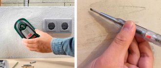
If there is a power failure in a house or apartment, you will need to quickly check the in-house wiring. This will not be difficult when the home technician has a multimeter and knows the basic safety rules for working with voltage.
Testing the wires with a multimeter is performed to determine their suitability, the absence of internal breaks, short circuits in the electrical circuit and determine the resistance of the circuit. The method is the most effective, proven and accurate. The most inexpensive digital model can easily cope with this task. Before testing the wires with a multimeter, a home mechanic must learn how to operate the measuring device and turn off the current on the network being tested.
Which multimeter is preferable to use?
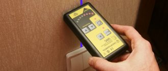
In the case when there is no such device in the house, and the owner is just planning to purchase it, you need to know about the important features of the choice. For home needs, it will be enough to purchase a budget model that has an audible dial tone indication.
On the panel of such a device there is a designation of a diode or sound. When testing for line continuity with this meter, a sound will be heard when the contact is closed.
Strictly speaking, this function is not necessary for testing wires with a multimeter, but it is very convenient and helps to perform testing more efficiently. The fact that the electrical circuit has a break is also indicated by “1” on the display. This means that the resistance between the test leads is significantly greater than the permissible limit. If there is no damage, the display will read around “0”.
Important! Wire resistance “0” is an ideal state and can only be implemented in home networks, and even not very long ones.
other methods
When checking multi-wire cables, you have to use other methods for marking the ends:
- System consisting of a power battery and telephone handsets. This check is performed by two people, but is very accurate and effective;
- A method that allows one to do the dialing involves the use of a specially manufactured transformer, the secondary winding of which has taps through a certain number of turns. The measuring core is connected to the lower terminal of the transformer, the rest are connected to the transformer terminals in ascending order of numbering. A voltmeter measures the voltage on the conductors of the other end relative to the signal end. The core with the lowest voltage will be first. The last number has the greatest tension;
- You can do without an assistant using a resistance store. Resistors of the selected value are connected between the conductors of the first end, starting with the signal wire. The conductors of the second side are selected with an ohmmeter in order of increasing resistance.
There are industrial and homemade devices that automate dialing. At the first end, the wires are connected to the corresponding terminals of the transmitting part, the receiver at the second end receives the wire number when touched with a probe.
How to safely ring wiring in an apartment
The work of repairing electrical equipment does not allow amateurism. There is a set of rules clearly established by the state for the safe operation of electrical networks, which allow not only to correctly test the intra-house electrical network, but also to protect the life and health of the performer from possible damage by electricity.
Basic safety rules that a home handyman must follow before wiring:
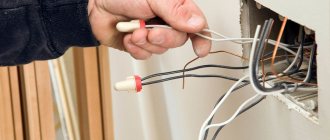
- In order to keep your hands free and the measurement contact more durable, when working with probes, experts advise using specialized clamp tips, which in everyday life are called “crocodiles”.
- Before checking the wiring with a multimeter, it is completely de-energized, including from low-current power sources, for example, batteries. This must be done before determining the phase.
- Before measuring resistance, look to see if there is a capacitor in the circuit being measured. It must first be discharged, otherwise the measuring device may burn out.
- When checking an extended cable, do not touch bare areas with your hands. Since it is disconnected from the power supply, it does not pose a threat to human life, but does affect the accuracy of the measurement.
- When testing a multi-core electrical cable, both ends are first stripped and separated, then the test is carried out alternately using “crocodiles”.
- The tester should not be used in a humid environment.
- It is not allowed to use probes with defects.
- When taking measurements, it is unacceptable to change measuring modes and rearrange the position of switches.
- You cannot check the properties of conductors if their parameters are higher than the permissible limits of the tester.
Important! The rotary lever is always set to the highest value first, to avoid damaging the multimeter. In the future, they gradually move to lower gradations until the readings of the measured value reach 2/3 of the established scale. In this case, the most accurate measurements with minimal error will be provided.
Safety regulations
When doing work with your own hands, follow the rules:
- The test is carried out on previously de-energized equipment.
- If the switchboard is located in the entrance, then it is necessary to install a warning sign or leave a person on duty.
- Do not touch contacts or exposed wires with your hands (even in the event of a power outage).
- It is recommended to use electrical gloves and boots that protect against electric shock.
If you are testing equipment with electrolytic capacitors, then before connecting the tester, the elements are discharged using a piece of wire with bare ends. If you have difficulty checking it yourself, you should call an electrician. Unqualified diagnostics or repairs using scrap materials reduce the reliability of electrical wiring and lead to short circuits or fire.
If the circuit breakers do not work
In this case, all electrical equipment and devices that are powered from this line are checked.
For example, if the lighting in a room stops working or 2 sockets on the wall do not work at the same time, then check the following nodes one by one:
- Turn off the power supply to the house network completely.
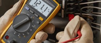
- Before checking the resistance, check whether the multimeter is working. This is done by short-circuiting the probes. The display should show “0”. If the readings are slightly different, for example, 0.1, this will indicate that the device has an error.
- Check the serviceability of the light bulb by unscrewing it from the socket. One probe touches the cartridge, and the other touches the end part. A buzzer and meter readings other than “0” and “1” indicate that the device is working.
- Check the wall switch by removing the panel, removing the screws, and removing it from the box. If there are no visible violations, then check the switch with a tester, installing probes on its contacts. The absence of a buzzer indicates that the switch is faulty and needs to be replaced. As a rule, after this the light appears in the room.
New building
It is most often necessary to check the electrical wiring in a new building after installation after purchase, before major repairs - finishing the walls and arranging furniture. The importance of this event lies in the fact that if you do not inspect the cable line from the very beginning, in the future it will be much more difficult to check the wiring under a suspended ceiling or behind plasterboard sheets.
First of all, you must calculate the total power of the electrical appliances that you will use, based on which, calculate the cable cross-section by power and compare this value with the cross-section of the conductor already laid in the walls. If the cross-section is insufficient, be sure to replace the electrics, however, as experience shows, such problems do not arise in new buildings.
The next step is to check the condition of the hidden electrical wiring. The insulation must not be damaged, and all wire connections must be made using terminal blocks or other connectors (for example, PPE caps), but not by twisting. Twisting is prohibited; see the list of permitted connection methods in Chapter 2.1. PUE clause 2.1.21. It is also important to determine the cable cross-section and check the ratings of the sockets. The socket group must have copper conductors with a cross-section of at least 2.5 mm2, the rating of the circuit breaker of the socket groups must not be greater than the rated current of the sockets, usually 16A.
If all the above requirements are met, the last thing left to do is to check the wiring in the apartment for load. In other words, you need to check yourself whether the switchboard is assembled correctly. When all equipment is connected and all lamps in the rooms are turned on, the machines should not operate.
If a circuit breaker trips, it means the electrical wiring is not able to withstand the load from the connected electrical appliances, as a result of which it will be necessary to replace the circuit breakers, divide the electrical wiring into groups, etc. If the circuit breakers in the panel do not turn off after turning on the load, then the home wiring is correct. It wouldn’t hurt to additionally check the reliability of the connection of the machines in the panel, as well as checking the ratings with the load that comes to them.
If the circuit breakers have tripped
This option indicates that there has been a serious failure in the electrical networks of the house, perhaps even a short circuit. Most likely, the wiring has failed, which can be checked by continuity.
To do this, the owner must sequentially complete the following steps:
- Use a screwdriver to disconnect the wire. Usually, it is located below and taken to the side. The “0” wire of this group is usually located at the 0 terminal under the circuit breaker.
- Before finding a fault, remove the light bulb from the socket and then check the lighting line with a multimeter, connecting the 1st probe to “0” and the 2nd to the disconnected wire. When a sound signal appears, the wire is shorted.
- At the top of the room they find and open the panel, disconnect the wires.
- Each pair is checked for the presence of a short circuit.
- After identifying the defective area with a short circuit, it is again tested with a circuit meter on the input panel. If there is a sound from the tweeter, then repairs must be made on the wire from the switchboard to the box. If not, then continue to examine other wires using a similar method.
Setting the device zero
Before the first measurement, it is worth checking whether the multimeter works at all - this is tested by pressing the tips of the probes against each other.
The device should beep and after a while you will see a resistance measurement result close to 0.0 Ohm.
You will not hear a beep on simple testers, but the measurement result will be similar. Now let's start checking for a wire break in the electrical circuit.
Checking the antenna cable
It should be noted that it is impossible to fully measure the quality of a TV signal with a standard multimeter. On sale you can find a special multimeter that has a built-in frequency meter. In this case, when setting up a specific channel, you can test for compliance between the specified and actual values of this parameter. In other cases, the tester can only be used to measure the antenna cable for resistance and wire integrity.
Important! Before you can test the antenna cable, you will need to have access to both ends. Then you can correctly measure the resistance with a multimeter.
In this case, an ohmmeter is used to determine the actual resistance between the pin and ring pin contacts. If, when checking the cable with a multimeter, the resistance is less than 20 ohms, then it is in good condition. If it shows infinity, then there is a break in the antenna cable. A resistance value of zero or close to it indicates a high risk of short circuit occurrence.
Old housing
It is more difficult to check the condition of the electrical wiring in an old house or apartment, especially if you have just bought a home and have no idea how the electrical wiring is done in the rooms. So, an audit of the electrical network must be performed using the following method.
Find all distribution boxes by room
By opening the cover, you can understand which cable is used for the hidden electrical wiring: aluminum or copper, as well as what cross-section of the wires. You should also immediately check the condition of the insulation - if the wiring is old, even the slightest bend in the cable will cause the insulating layer to begin to crumble or crack. Such electrical wiring must be changed without any reservations.
It would be correct to check the insulation resistance with a megger (so to speak, for breakdown and current leakage). Its resistance must be at least 0.5 MOhm. But not everyone has such a device, so “for the sake of decency” you can at least measure the resistance with a multimeter, although this can hardly be called a normal test. If the insulation resistance is poor, leaks will occur and the RCD may trip if you upgrade the electrical panel. It is equally important to immediately inspect all wire connections - there should be no damage or twists, especially aluminum and copper.
If necessary, you should immediately connect the wires with terminal blocks instead of twisting them. We talked in detail about how to find a junction box in the wall of an apartment building in the corresponding article.
Check sockets and light switches
In sockets, it is necessary to inspect the integrity of the wires and insulation, and also determine the rating for which they are designed. If three-wire wiring is connected to the sockets, it is imperative to determine where the phase is, where the zero is and where the ground is. To do this, you will need a multimeter or an indicator screwdriver, and we provided the technology for determining phase and zero in the corresponding article.
How to check the intercom wire
The intercom may not work due to incorrect switching or a damaged communication line. In order to restore functionality, you will need to determine the breakdown points and correctly establish their polarity.
The need to test this network arises if during the installation process “+” and “−” are mixed up and you need to correctly identify them with a tester. To do this, select the constant voltage mode, setting the indicator to 20 V. The black probe (–) is connected to COM, and the red probe (+) to the V, mA socket.
Then the probes are pressed to the wire or to the contact group. If the meter display shows values without unnecessary icons, the poles are selected correctly. If a minus appears on it, the wires are mixed up, they need to be swapped.
The test is carried out for each pair of wires. The multimeter readings will indicate the condition of the intercom wire:
- Operating condition, 600–800 Ohms, when changing probes, it tends to infinity;
- 1200–1300 Ohm, the line is broken or there is a failure in the intercom handset;
- 0–260 Ohm - short circuit on the communication line.
Conclusions and recommendations
- We always carry out resistance measurements in the free state of the tested conductors. Measuring a live wire is lethal. At least for a multimeter.
- Measuring a circuit is actually testing its electrical resistance.
- When the conductor is not damaged, the measurement result should be no more than a few ohms.
- Before performing the break measurement itself, it is worth performing a test measurement on the probes to check whether the device is working.
Checking for broken wiring in a car is done in a similar way, with the only difference being that you don’t have to worry about a 220 V current shock due to the absence of one (this does not apply to electric cars - there are even 600 V there!).
Checking wiring integrity using improvised means
If the home technician does not have a multimeter, and the wiring needs to be checked urgently, then you can use improvised means. Before wiring electrical wiring using improvised means, you will need:
- Standard 4.5 V square battery;
- mini light bulb 3.5 V;
- a pair of mounting wires and an alligator clip.
The simplest circuit is assembled on their basis. If you connect it to the ends of the wire under test and the light comes on, then the line is working. Otherwise, the conductor has a break.
Thus, we can draw a line. For a home handyman, if necessary, it will not be difficult to test all the wires located in the house and apartment with a multimeter: lighting lines, intercom and TV cables. The main thing is that before checking the integrity, choose the right measurement interval correctly and adhere to safety rules when working on electrical installations.
Timing for replacement of electrical wiring
After the electrical wiring has reached the end of its service life, it needs to be completely replaced without testing or inspection. The timing of inspection, replacement or interval between major repairs is established by VSN 58-88(r) (departmental building codes) and is:
- for hidden indoor networks 40 years;
- for open 25 years;
- for main wiring between apartments and input and distribution devices 20 years;
- for production and technical premises and lighting of public places 10 years.
Checking the electrical wiring in an apartment or private house, despite its apparent complexity, if you have the necessary knowledge and a minimum set of tools, you can do it yourself, without inviting a qualified electrician.
Analog inductive probes
Analog inductive probes can accurately identify the pair of wires at the remote end, but the pair must be disconnected from the active equipment and open circuit. In addition, such receivers are unlikely to be able to trace a line under plaster and behind a false wall. This is only possible if used in conjunction with a high power generator. At the same time, they are good at identifying low-frequency harmonics emanating from power wiring under load. This allows tracing hidden under plaster or in a hollow wall.
Video of wiring traced with an inductive probe:
The most popular and universal inductive probes are the following models:
| 200B-G | TEP-200 | CT15 | 200EP-G | |
| LED indication | • | • | ||
| Sound indication | • | • | • | • |
| Frequency range of the received signal | 500 Hz – 5 kHz | 100 Hz – 20 kHz | 500 Hz – 5 kHz | |
| Volume | 30 dB | 30 dB | ||
| Determining the polarity of a telephone line | • | |||
| Received signal type | analog | analog | analog | analog |
| Pairing with a headset | • | • | ||
| Pairing with a handset | • | • | ||
| Workspace lighting | • | |||
| Tip type | plastic | plastic | plastic | metal, plastic |
They are compatible with all (regardless of manufacturer) analog signal generators whose output frequencies are within the operating range of the inductive probe.
Checking the electric heating element
You can also ring an electric water heating element with a multimeter. To do this, the probes of the device must be attached to the contact plates of the heating element. If the resistance reading is small, then the heating element is working. With very large values or one (depending on the model), the heating element is damaged and requires replacement.
Note! Sometimes one housing may contain two heating elements connected to voltage in parallel. In this case, you need to ring them separately, having first removed the jumper between them
It is very important for boilers and other water heating devices to ring the contacts of the heating element for penetration into the body. To do this, the probe is connected to one of the contacts, and the second - to the body of the heating device
If the tester shows a certain value, the internal insulation has been damaged in this heating element. To prevent electric shock, the heating element must be replaced.
Continuity using a transformer
This method is effective for testing unrolled laid cables with wires of the same color. In this case, step-down transformers are used with different voltages at the taps of the secondary winding.
- The primary winding of the transformer is connected to a 220V AC source;
- The beginning of the secondary winding to the ground loop, to which the cable shield is closed;
- The remaining secondary winding taps with different voltages to the ends of the wires;
- On the other side of the cable, a multimeter is used to measure the corresponding voltage between the ground loop and the cable wires. Thus, the integrity of the core is checked and marked.
Diagram for connecting the cable to the transformer for dialing.
The multimeter is set to AC voltage measurement mode. It is recommended to use devices from Western manufacturers, since in this case the measurement mode is used, not the indication mode. Chinese S-99 type multimeters are very poorly calibrated; inaccurate voltage measurements can lead to errors when marking the cable. Therefore, for tapping a cable using a transformer, where voltage measurements are made, it is better to use a pointer device of the Ts-4342-M1 type.
Characteristics of the combined device Ts 4342 M1:
| Accuracy class | 2,5/4,0 |
| measurement ranges | |
| DC current in mA | 0,05 — 2500 |
| AC current in mA | 0,25 — 2500 |
| Voltage, DC | 0,1 — 1000 |
| Variable voltage in volts | 1,0 — 1000 |
| DC resistance in kOhm | 0,3 — 10000 |
| signal level when measuring voltage in dB(-) | -10 to+15 |
| frequency range in Hz | 45 — 2000 |
| Power supply | autonomous |
| Dimensions in mm | 215*115*90 |
| Weight in kg | 0,9 |
| operating temperature | from -10 to +40°С |
In most cases, all multimeters have a classic layout of controls with minor differences.
When taking measurements, you need to carefully look at the inscriptions with symbols. Summary table of main parameters for different models of multimeters:
| Model | LCD screen | U— | V~ | I— | I~ | R | The dial is connected. | Diode testing | Transistor testing |
| M830B | 7 segments 3.5 digits | 0.1mV - 1000V | 0.1V - 700V | 0.1mA- 10A | — | 0.1W-2mW | — | * | * |
| M830 | 7 segments 3.5 digits | 0.1mV - 1000V | 0.1V - 700V | 0.1mA- 10A | — | 0.1mW - 2mW | * | * | * |
| M832 | 7 segments 3.5 digits | 0.1mV - 1000V | 0.1V - 700V | 1mA- 10A | — | 0.1W-2mW | * | * | * |
| M838 | 7 segments 3.5 digits | 0.1mV - 1000V | 0.1V - 700V | 1mA- 10A | — | 0.1W-2mW | * | * | * |
To set the multimeter to the AC voltage measurement mode, you need to set the batch switch for changing modes in the sector with the “ V ~” icon to the maximum value within which measurements are taken. In our case, this will be any measurement limit greater than 20V; the wires from the probes are installed in the same connectors as when measuring resistance.
Determining the reason for lack of access to the Internet
In a pop-up window on the computer monitor, the message “Network cable is not connected” appeared, the LED on the network card did not light up.
You insert and remove the RJ-45 plug in the hope of poor contact in the connection and realize that the cable is faulty. If you do not have a separate network card installed in your computer, and the network cable plug is inserted directly into the motherboard, the LED will not light if the connection is disabled by software. Nowadays, a twisted pair network cable is often first connected to the router, which sometimes freezes. Therefore, first of all, you need to reboot the router. To do this, just disconnect it from the power supply for a minute and then turn it on again. It is quite possible that access to the Internet will be restored after this.
A shutdown can occur without your direct participation, for example due to unstable network voltage, running unlicensed programs or a virus. To check in Win XP you need to go to: Start / Settings / Control Panel / Network Connections and make sure that the connection is connected. Less often, but it also happens, the network card driver does not work correctly. You can check: Start / Settings / Control Panel / System / Hardware / Device Manager / Network Cards. There should be no warning signs.
Network cards very rarely fail; this sometimes happens after a severe thunderstorm. You can check the functionality of the network card by connecting it to a known-good line or installing it in another computer, not forgetting to install the driver for it. Sometimes it is possible to get a network card to work by moving it to an adjacent slot on the motherboard.
A call to the provider's technical service will help check the functionality of the line on their part. If everything is in order with the computer and the provider, it means that the twisted pair cable has failed and requires repair. You can, of course, call specialists and wait, but if you wish, it is possible to diagnose and repair the twisted pair cable yourself.
The following malfunctions of a twisted pair cable are most likely: - complete break of one or more wires - occurs frequently; - a short circuit between the conductors of one twisted pair or between the wires of adjacent pairs - is less common.
Independent dialing
It is best to ring the telephone cable using the handset of the device. This method is characterized by simplicity and mobility.
- An assistant is invited.
- The common core is determined. She can be anyone. Others are called in relation to the selected core. The selected one must be ringing initially.
- The first clamp of the main tube is connected to the main core. The second - to the other.
- The first clamp of the auxiliary tube is connected to the main core on the opposite side of the cable.
- The second switches alternately over the others. You need to find the one to which the assistant connected.
- When connected to the desired core, a crackling sound will be heard, indicating the occurrence of a closed circuit.
- A method for marking the detected core is discussed with an assistant. Pre-prepared tags are placed on the ringed type of core on both sides.
- The process is repeated for each subsequent wire.
- If there is no break, the conductors are inserted into the terminal block.