The comfortable living of all its inhabitants and the uninterrupted operation of household appliances depend on the correct connection of electrical wiring in the house. Do you agree? To protect the equipment in the house from the consequences of overvoltage or short circuit, and the inhabitants from the dangers associated with electric current, it is necessary to include protective devices in the circuit.
In this case, it is necessary to fulfill the main requirement - the connection of the RCD and circuit breakers in the panel must be done correctly. It is equally important not to make a mistake when choosing these devices. But don't worry, we'll tell you how to do it right.
This article will discuss the parameters by which RCDs are selected. In addition, here you will find features, rules for connecting machines and RCDs, as well as many useful connection diagrams. And the videos given in the material will help you put everything into practice, even without the involvement of specialists, if you have at least a little knowledge of electrical engineering.
Where to install?
As a rule, the protective device is installed in an electrical panel, which is located on the landing or in the residents' apartment.
It contains many devices that are responsible for metering and distributing electricity up to a thousand watts. Therefore, in one panel with an RCD there are machines, an electric meter, clamping blocks and other devices. If you already have a shield installed, then installing the RCD will be easy. To do this, you will only need a minimal set of tools, which includes pliers, wire cutters, screwdrivers and a marker.
The process of installing automation in an electrical panel: step-by-step instructions
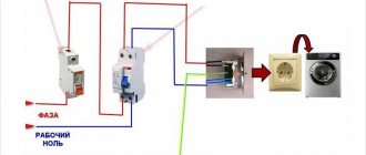
Let's consider the option of assembling an electrical panel for a one-room apartment; a switch, a protective multifunctional device will be used here, then a group of RCDs will be installed (type “A” for a washing machine and dishwasher, because such a device is recommended by the equipment manufacturer). After the protective device there will be all groups of circuit breakers (for air conditioning, refrigerator, washing machine, dishwasher, stove, and also for lighting). In addition, pulse relays will be used here; they are needed to control lighting devices. A special module for wiring will also be installed in the panel, which resembles a junction box.
1: First, you need to place all the automation on the DIN rail, in the way we will connect it.
This is how the devices will be located in the panel
In the panel there is first a switch, then an UZM, four RCDs, a group of circuit breakers of 16 A, 20 A, 32 A. Next are 5 pulse relays, 3 lighting groups of 10 A and a module for connecting the wiring.
2: Next we need a two-pole comb (to power the RCD). If the comb is longer than the number of RCDs (in our case, four), then it should be shortened using a special machine.
Cut the comb to the required size, and then install stops along the edges
3: Now all RCDs should be fed together by installing a comb. Moreover, the screws of the first RCD should not be tightened. Next, you need to take cable sections of 10 square millimeters, remove the insulation from the ends, make crimping with lugs, and then connect the switch to the UZM, and the UZM to the first RCD.
This is what the connections will look like
4: Next, you need to supply power to the switch, and accordingly to the UZM with the RCD. This can be done using a power cable, which has a plug at one end and two crimped wires with tips at the other. Moreover, you first need to insert the crimped wires into the switch, and only then make a connection to the network.
Next, all that remains is to connect the plug, then set the approximate range on the UZM and click on the “Test” button. So, you can check the functionality of the device.
Here you can see that the UZM is functioning, now you need to check each RCD
5: Now you need to turn off the power and continue assembly - you should power the group of circuit breakers on the central rail with a comb. Here we will have 3 groups (the first is the hob/oven, the second is the dishwasher and washing machine, the third is the sockets).
We install the comb on the machines and transfer the slats to the panel
6: Next you need to move on to zero buses. There are four RCDs installed here, but only two zero buses are required, because they are not required for 2 groups. The reason for this is the presence of holes in the machines not only at the top, but also at the bottom, so we will connect the load to each of them, so a bus will not be required here.
In this case, you will need a cable of 6 square millimeters, which must be measured in place, stripped, clamped at the ends and connected to the RCD with its groups.
Using the same principle, it is necessary to power the devices with phase cables
7: Since we have already connected the automation, all that remains is to power the pulse relays. They should be connected to each other with a 1.5 square millimeter cable. In addition, the machine phase should be connected to the junction box.
This is what the assembled shield will look like
Next, you need to take a marker to mark the groups for which this or that equipment is intended. This is done in order to avoid confusion in case of further repairs.
Safety precautions when working with RCDs and automatic machines
Common mistakes made by experts
Sometimes even electricians with extensive experience make some mistakes when connecting machines and RCDs. In order to avoid negative consequences, it is necessary to consider them in more detail.
Table 2. Errors during installation.
| Error, illustration | Description |
| Connecting cores without termination | This is one of the common mistakes that craftsmen make when in a hurry, because this way it can be easier to connect the wiring. However, this does not allow the ends to be fully clamped, so after a short period of time the contacts will become weak. At the same time, they will begin to overheat, so they attach tips to the ends of the wires or squeeze them tightly. |
| Contact of the insulating layer | As we discussed in the previous instructions, first the wire must be stripped of the insulating layer to the required length, and only then placed in the clamp and tightened with a screw. However, some users experience sudden burnout of the machine or intermittent operation when new mechanisms are installed. A common cause of the problem is precisely the insulation getting under the contact of the machine. This leads to the fact that after connecting the protective layer, the wiring begins to heat up. Over time, it may catch fire , which will lead to a fire in the panel. |
| Different thicknesses of cores in one clamp | Automatic switches should not be combined with jumper wires of different thicknesses - this will lead to the fact that when tightening the screw, only the large core will be securely fixed, and the small one will have weak contact. Due to such negligence of electricians, fires that affect the insulation and switchboard circuit breakers. The photo shows a clear example of connecting machines with wires with a thickness of 4 square millimeters and 2.5 square millimeters. This led to the fact that after overheating, the wiring and body of the machine melted. Even if you take wires with a minimal difference in thickness ( 1.5 and 2.5 square millimeters), you should not expect other consequences, because they still cannot be tightly connected in the clamp. |
| Soldering the ends of the cores | Some craftsmen, due to a lack of skills, prefer to use an unsafe method of terminating cores - soldering. They do this because they save money on the purchase of special devices. In addition, electricians prefer to use this method for urgent installation. However, the use of this method is prohibited . After all, the contact is less easily fixed by the clamp and begins to weaken over time, so it will have to be constantly tightened. In practice, such actions are quickly forgotten. What causes a fire ? |
Note! The safety of electrical wiring should always come first, therefore, even as temporary measures, such methods of connecting machines in a panel should not be used.
Prices for electrical panels
Electrical panel
Rated breaking current of RCD
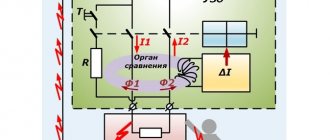
The rated breaking current of the RCD I∆n (set) is the current at which the RCD trips (turns off). The RCD settings are 10 mA, 30 mA, 100 mA, 300 mA, 500 mA. It should be noted that the non-release current, when a person can no longer open his hands and throw away the wire on his own, is 30 mA or higher. Therefore, to protect a person from electric shock, an RCD with a breaking current of 10 mA or 30 mA is chosen.
The rated breaking current of the RCD I∆n or leakage current is also indicated on the front panel of the RCD.
A 10 mA RCD is used to protect electrical receivers in damp rooms or wet consumers, i.e. washing machines and dishwashers, sockets that are located inside the bath or toilet, light in the bathroom, heated floors in the bathroom or toilet, light or sockets on balconies and loggias.
SP31-110-2003 p.A.4.15 For plumbing cabins, bathtubs and showers, it is recommended to install an RCD with a rated differential breaking current of up to 10 mA, if they have a separate line, in other cases, for example, when using one line for a bathroom, kitchen and corridor , an RCD with a rated residual current of up to 30 mA should be used.
Those. The RCD with a setting of 10 mA is installed on a separate cable, to which only the washing machine is connected. But if other consumers are still powered from the cable line, for example, sockets in the corridor or kitchen, then in this case an RCD with a response current (set) of 30 mA is installed.
ABB produces RCDs with a leakage current of 10 mA only at 16A. Schneider Electric and Hager have RCDs for 25/10 mA and 16/10 mA in their product line.
The 30 mA RCD is installed on standard lines, i.e. regular household sockets, lights in rooms, etc.
PUE clause 7.1.79. In group networks supplying plug sockets, an RCD with a rated operating current of no more than 30 mA should be used. It is allowed to connect several group lines to one RCD through separate circuit breakers (fuses).
RCDs 100, 300, 500 mA are called fire protection; such RCDs will not save you from a fatal electric shock, but will save your apartment or private house from a fire due to faults in the electrical wiring. Such 100-500 mA RCDs are installed in input panels, i.e. at the beginning of the line.
In the USA they use RCDs with a rated breaking current of 6 mA, in Europe up to 30 mA.
It should be noted that the RCD is turned off within the setting range of 50-100%, i.e. if we have a 30 mA RCD, then it should turn off within 15-30 mA.
There are designers who promote double diffs. protection of “wet” consumers. This is when, for example, a washing machine is connected to a 16/10 mA RCD, which in turn is connected to a 40/30 mA group RCD.
In the end, what do we get? At the slightest “sneeze” from the washing machine, we turn off the entire group of machines (kitchen light, boiler and room light), because in most cases it is not known which RCD 25/30 mA or 16/10 mA will work, or whether both will work.
According to the set of rules for the design of electrical installations of residential and public buildings:
SP31-110-2003 clause A.4.2 When installing an RCD, selectivity requirements must be consistently met. With two- and multi-stage circuits, the RCD located closer to the power source must have tripping current settings and response time at least three times greater than that of the RCD located closer to the consumer.
But in fairness, it should be noted that if the electrical wiring is installed efficiently, then the RCDs do not operate for years. Therefore, in this case, the final word belongs to the customer.
Types of electrical networks
In order to learn how to connect a protection device correctly, you need to familiarize yourself with the types of household electrical networks. Currently, there are three options for residential power supply systems:
- TN-C;
- TN-S;
- TN-CS.
Everyone knows that in residential premises there are two-wire or three-wire wiring. The first option is called TN-C due to the type of grounding. In this case, the zero wire N and the protective PE are combined into a common PEN.
This type of system allows you to save cable, but does not provide a sufficient level of protection. In the case of a two-wire circuit, there is no grounding of the outlets. To protect against electric shock when voltage comes into contact with the metal parts of consumers, it is often zeroed out, hoping that the circuit breaker will operate as a result of a short circuit that occurs in this case.
The TN-C system is not used in new houses and apartments.
The system using a three-core wiring cable in a TN-S house is the safest and involves separate neutral and protection conductors throughout the entire power supply circuit: from the substation to the consumer in the house. In this case, a five-wire line will be required in a three-phase residential power supply network and a three-wire line in a single-phase one, which leads to additional costs.
The TN-CS system involves combining N and PE conductors into a common PEN, and then separating them when entering the building. At the separation point, re-grounding is created. This type of electrical network is economical and is used most often. Note that the TN-C system can be easily converted to TN-CS. In this type of network, if the PEN conductor breaks, a high voltage may occur at the entrance to the building, which can be counteracted by installing a voltage relay. Read about the selection and installation of voltage relays in the article “Protection device against surges, surges and overvoltage of a 220V network in a private house or apartment.”
Electrification
To correctly carry out electrification of an object of any complexity, you need to perform the following steps:
- draw up an electrical diagram taking into account all the features of the electrical wiring of a particular object;
- correctly determine the total power consumption;
- determine the number of electrical groups and the power of each group;
- decide on the installation location of the distribution panel and how many modules it should have;
- select a metering device (electricity meter);
- correctly connect outgoing and incoming lines;
- connect the switchboard to the networks of the energy supply company.
Connection diagram for a three-phase RCD: 4 options for a private house
Below I consider cases of using fire-fighting and conventional modules in different situations.
Fire protection RCD for a private home: how to choose and install correctly
A fragment of the connection diagram for a four-pole fire protection RCD at the entrance to a private house explains the main principle of its selection based on differential current.
It is placed at the entrance to the building for protection:
- input cable;
- lines to consumers where individual residual current devices are not used;
- acting as a reserve in case of failure of the main module.
The fire protection RCD is connected to the power supply circuit of the house with mandatory observance of the selectivity of its operation. This is achieved in a comprehensive manner by two settings:
- threefold reserve of the differential current setting in comparison with any group or individual module located below;
- delay in response time by at least 3 times.
A fragment of the above connection diagram shows that the differential current of the fire protection module IΔns is three times higher than the leakage setting IΔn1 or IΔn2 for any group of consumers.
Fire protection RCDs are designed to be triggered by leakage currents of 100, 300 or 500 mA, and human protection modules from differential current are manufactured with settings of 30, 10 or 6 milliamps.
The ability to set a time setting for selective operation is indicated on the module body with the Latin letter “S”.
The correct choice of settings for fire protection, group and individual RCDs for differential current and shutdown time of an emergency is an obligatory principle of reliable liquidation by protecting the damaged area while leaving serviceable equipment energized.
Connecting a three-phase RCD: 4-pole circuit using neutral
A simplified diagram for connecting a four-pole RCD to a three-phase network can be represented as follows: at the output of the working zero, a busbar is used to distribute neutral potentials N to connected consumers (circuit with neutral).
Consumers can be powered from all 3 phases or just one. The same circuit allows you to simultaneously protect three different single-phase circuits, provided that a common neutral is used.
At the same time, they try to arrange the operation of the equipment in compliance with the uniform distribution of load currents across all phases.
Connecting a three-phase RCD: 4-pole circuit without using a neutral
The case of using a symmetrical load, in which all currents in the phases are always equal, allows one to abandon the operation of the neutral wire and simplify the design.
An example of such a connection is the protection of a three-phase asynchronous electric motor. Its stator windings can be assembled in a star or delta configuration, which provide equal resistance between phases.
The working zero potential is connected to the input contact of a four-pole RCD, and nothing is connected to the output. The potential output terminal N remains empty.
This technique allows you to save money by connecting the motor to the power circuits with a cable with four rather than five cores: three for phase potentials and one for the protective PE conductor.
It is mounted on a special housing grounding bolt.
Connecting a three-phase RCD: diagram for a single-phase network
The proposed option is not typical.
It is used as an exception in three cases:
- The owner has an extra protection module that needs to be put into operation. Otherwise, it will simply gather dust without use.
- The assembled single-phase wiring is planned to be converted to three phases in the near future.
- Temporary replacement of a module that fails when an accident occurs.
In all three cases, it is necessary to pass the phase potential through those terminals to which the “Test” button winding is connected. Otherwise, it will not work during manual checks.
In this short article I tried to provide the most necessary material. The owner's video, Electrician's Notes, clearly illustrates how to connect an RCD correctly and select it based on its rated current and leakage current. I recommend watching it.
This is interesting: Is it possible to connect a pass-through switch to the hood in the shower?
Connection to a three-phase network
Three-phase 380V power is used in factories and small workshops. They power machine tools, various furnaces and asynchronous motors (elevators). Installing an RCD in a three-phase network is no fundamentally different from a single-phase one. The difference lies only in the number of pins on the protective device. The three-pole RCD has 8 contacts for connecting cables. Four incoming L1, L2, L3 and N and 4 outgoing with similar markings.
Three-pole RCD
When connecting, there may be confusion in the wires. To understand the color and letter markings, it is enough to know the simple relationships from the table.
| Russian designations | European designations | ||
| Phase A | Yellow | L1 | Brown |
| Phase B | Green | L2 | Black |
| Phase C | Red | L3 | Grey |
| Neutral wire | Blue (cyan) | N | Blue (cyan) |
| Ground wire | P.E. | Green-yellow | |
Introductory three-phase RCD + separate group
The device is installed after the introductory three-pole circuit breaker. Three power supply conductors pass through it. Then they go directly to the RCD. Connection is carried out taking into account the markings. Terminal L1 at the output of the machine is connected to L1 on the protective device, L2 to L2, and so on.
After the introductory three-phase RCD, the wires go to the group circuit breakers. The zero core is connected to the common N bus. Ideally it is blue. Then the phase wires from the machines are connected to single-pole group RCDs and distributed to consumers.
Input protective device + three-phase meter
The scheme is similar to the previous one. However, in this case a three-phase electricity meter is added. It has 8 pins designed to connect 3 phases and zero. The metering device is mounted at the output of the input machine. After the meter there is a three-phase RCD. Behind it are group single-pole circuit breakers and residual current devices.
RCD and group circuits
According to the standards, RCDs are installed on group circuits (functional groups) of sockets, lighting, power equipment, as well as in electrical circuits of single installations (devices).
Scheme 3, connection of RCD 380 V, 11 kW
In this diagram, RCDs are connected to an electrical network, 380 Volts, and a design load of up to 11 kW. This could be a private house or apartment. According to the diagram, a general fire protection RCD (25 A/100 mA) is installed together with a meter in the UERM (Multi-box floor distribution device - a modern floor panel). The electrical network of the room is divided into 5 groups, three of which are protected by a 16 A/30mA RCD and the bathroom circuit is protected by a 25A/10mA RCD.
Scheme 4, 8 group circuits
In diagram 4, RCDs are connected to an electrical network of 380 Volts, and a design load of up to 11 kW. This scheme provides 8 group circuits, 6 of which are protected by RCDs. (4 uzo 16A/30mA and 1 uzo 25A/10mA)
Scheme 5, connecting an RCD in a private house
Installation of an RCD in a private house with power supply from a pole. Supply voltage 220 Volts.
A fire protection RCD (32A/100mA) is installed at the input of the power cable in ShchKVs (apartment panel built-in with glass) together with the meter. The ShchKVs switchboard can be replaced by ShchKNs (apartment mounted switchboard) or a ShchVU switchboard (introduction switchboard).
The second panel in the house, ShchR (distribution panel), three RCDs (25A/30mA) are installed in it to protect the circuits of power outlets.
Scheme 6, RCD in a large apartment
Electrical wiring diagram for a large apartment or house. The incoming protective device is installed before the meter, the question is why? If we are talking about installing an RCD as such, then installing an RCD before the meter is incorrect. It is possible to install a protective device before the meter if it is a differential circuit breaker, but there is already a circuit breaker installed here.
Scheme 7, RCD in the tn-s network
Residual current device in an apartment, without a fire protection circuit breaker, in a tn-s network.
If we consider this diagram as a diagram of only an apartment, then it is quite acceptable to divide the PEN conductor into PE and N conductors in the floor panel, and the network itself is of the tn-cs type.
Schemes 9 and 10, correct and incorrect connections of the RCD
These are simple schematic diagrams for the correct and incorrect connection of an RCD
It is worth paying attention to the incorrect connection of the RCD
- (1) this is the connection of a differential machine,
- (2) and (3) this is the connection of RCDs with circuit breakers.
Scheme 11 and Scheme 12, ouzo on circuit diagrams
Simple circuit diagrams, 220 Volts. They perfectly and correctly show the connection of the RCD in the assembly: introductory automatic device - metering device - fire protection RCD.
Scheme 13, Municipal apartment connection scheme
Municipal apartment connection diagram. Fire RCD (50A/100mA) in the floor panel and general RCD in the apartment panel (40A/30mA). The name speaks for itself, the scheme is economical.
Minimum connection diagram for an apartment with one fire protection RCD (40A/30mA).
Diagram 15, Optimal apartment connection diagram
Two RCDs are planned for the apartment, with one device protecting two groups at once (sockets and kitchen). The diagram clearly illustrates the rule formulated above regarding a separate grounding bus for RCDs into several groups.
Similar to scheme 15, but for unknown reasons, a separate grounding bus has been removed.
Scheme 17, Selective ouzo
The latest RCD connection diagram. Here we see an illustration of another rule for installing RCDs: the RCD installed at the input must be selective, that is, have a delay in shutdown time compared to other RCDs in the network.
These are all 15 RCD installation schemes, in fact there are 17 of them. Some are controversial, most are useful.
Antipov Igor, especially for the Do-It-Yourself Electrics website
What is a three-phase network and how to connect an RCD in it?
In a three-phase network there is also a phase and a zero, only there are three phase conductors (“L 1”, “L 2”, “L 3”). The voltage between any of the phases is 380 V, between phase and zero – 220 V. It is very important in such an electrical network to distribute the load evenly between the phases. If one phase is loaded more and the other less, a imbalance will occur, and as a result, an emergency situation.
Similar to a single-phase network, a three-phase network can consist of four or five conductors. In the first case, there are three phase wires and a neutral wire; in the second, a protective grounding conductor is also added.
An example of assembling a three-phase electrical panel in the video:
Installation of an RCD in a three-phase network is carried out in exactly the same way as in a single-phase network: you can install it only at the input or connect one more residual current device to each outgoing group of consumers. An equally appropriate option is when an electricity meter is connected between the input circuit breaker and the RCD.
In apartments you are unlikely to find a three-phase network anywhere, but for private houses a voltage of 380 V may be required to connect pumps, motors, and machines.
Errors in connecting the RCD
Novice electricians and home craftsmen often do not know how to properly connect RCDs and circuit breakers. When connecting differential current protective devices, the following rules must be strictly followed:
- residual current devices must be connected in series with circuit breakers;
- The protected electrical equipment must be grounded.
Despite the simplicity of the rules, there are often repeated errors. Many craftsmen believe that disconnecting devices should be triggered when a person touches parts of electrical equipment that are energized as a result of an insulation failure. This is a misconception. The protection should not work when a person touches it, but at the moment the insulation is broken. Therefore, protective grounding is used together with the RCD.
The second common and dangerous mistake is the use of “zeroing”. In this case, the neutral conductor is connected to the housing of the protected electrical equipment. This scheme is dangerous because if the neutral wire breaks, there is a possibility that a phase will appear on the protected equipment.
Another common mistake is connecting neutral conductors powered by different protective devices. Such a connection necessarily leads to the appearance of leakage currents and the activation of protection devices.
Watch this video on YouTube
Connecting a residual current device to a two-phase network
The case is exotic. Two-phase power supply networks were abandoned at the beginning of the twentieth century. The chance of a modern electrician encountering them is close to zero. It is worth thinking about connecting an RCD to a two-phase network as an elective.
Each pole of the socket is phase. It has a potential to ground of approximately 127 volts. The connection diagrams for residual current devices are similar to single-phase ones. But the circuit breaker must be mounted on each of the two incoming phases. Of course, it is impossible to connect one of the supply wires to grounding or the electrical panel housing.
Additional Information. Two-phase power supply to residential buildings is a thing of the past. However, many modern low-power transformers have windings designed from 380 V. It operates from 2 phases. Typically these are transformers for auxiliary needs in industrial equipment. It is not practical to install a separate RCD for them.
Application of two-pole devices
The connection diagram for a two-pole circuit breaker involves the use of pulse transformers. If they are set to a step-down type, the frequency will change quite quickly. To solve this problem, many experts recommend installing high-quality zener diodes. In this situation, they must withstand a negative resistance of at least 45 ohms. In this case, selectivity typically depends on the types of capacitors.
If we consider pass-through models, then their linear distortion frequency is quite high. At the same time, they can withstand a peak voltage of about 300 V on average. Resistors for the device are suitable both synchronous and asynchronous. In turn, relays are selected based on the type of power cable. If we consider three-core models, they have good wiring properties. In this regard, they will need a magnetic relay.
Scheme options
This is not to say that there is one specific pattern. Each case has its own characteristics, so connecting the RCD can be done in different ways. Firstly, the device is used in single-phase and three-phase voltage networks (these are two different circuits). Secondly, you can install an RCD at the entrance and thus protect the entire apartment from current leaks. And you can install devices for each individual line, thereby protecting only a certain section of the electrical network.
Video example of connecting an RCD in a single-phase network:
Since the circuit diagram for connecting an RCD has several options, it is very important that you can read them. Nowadays, the passports of many electrical household appliances and equipment indicate how and through what type of RCD they must be connected to the electrical network.
Let's look at how to properly connect an RCD using several general examples.
What is a single-phase network?
With a single-phase electrical network, consumers are powered through two conductors - a phase and a working zero. The rated voltage in such networks is 220 V.
A single-phase network can be of two-wire or three-wire design. In the first case, two conductors are used - phase and neutral; in the diagrams they are designated by the English letters “L” and “N”.
The second option, in addition to phase and zero, also provides for the presence of a protective grounding conductor (its designation is “PE”). The main function of this grounding wire is to further protect people from electric shock. Due to its connection to the housings of electrical appliances, in the event of a phase short circuit to the housing, the power supply will be cut off. This will save both human life and the equipment itself from burnout.
Now let’s talk about what the connection diagram for an RCD in a single-phase network might be.
Input connection (single-phase network)
In this case, the installation of the RCD is carried out in the panel after the introductory two-pole circuit breaker. Following the residual current device, outgoing circuit breakers are located. This circuit for switching on the RCD provides simultaneous protection against current leaks to all outgoing consumers.
The disadvantage of the scheme is that it is difficult to find the location of the damage. For example, a phase short circuit occurred to the metal body of some household appliance that is currently plugged into the outlet.
The RCD is triggered and the voltage in the apartment disappears. If at this time several devices were plugged into the sockets, then immediately identifying the damaged one will be problematic.
This scheme also has positive sides. Due to the fact that only one residual current device is used, installation of the distribution panel will be cheap, and it will be small in size.
Keep in mind that another type of such a circuit has become widespread; in it, it is customary to install an electrical energy meter between the input circuit breaker and the RCD.
Connection at the input and output lines (in a single-phase network)
With this version of the circuit, the RCD is installed after the input circuit breaker and also on each outgoing line.
We’ll talk about what selectivity is a little lower.
For example, there was a current leak on one of the outgoing lines. The device that protects this particular group should operate.
If for some reason the RCD does not work, then after a certain time (this is called a time delay) the general RCD at the input will turn off; it, as it were, protects the outgoing one.
The undoubted advantage of such a scheme is that at the moment of damage only the emergency line will be turned off, and the voltage supply will not stop in the rest of the apartment.
The disadvantages of such a scheme are the large dimensions of the distribution panel and the high cost (the RCD is not a cheap thing, and with this option you will need several of them).
The video shows a comparison of several connection schemes:
https://youtube.com/watch?v=EQs-iqz-kAE
You can save a little and omit the single-phase RCD at the input in this scheme, that is, install only group devices on the outgoing lines. Many electricians generally consider an introductory RCD to be a waste of money, because each line already has its own protection. But as we said above, it is a kind of safety net in case the group device fails. Therefore, it all depends on your financial capabilities. If you have money, install a circuit with an RCD at the input. If it’s so expensive, install only outgoing devices, that will also be great. Many people do not install an RCD at all, preferring to save money on their own safety.
Getting to know your device
Before connecting the RCD, it would be nice to understand its design, operating principle and main functions.
Why is it necessary?
The main task of an RCD is to protect people from electric shock. A person may accidentally touch exposed live wires. Or touch the body of a household electrical appliance on which potential has appeared due to insulation damage. In any of these cases, the device will work and the voltage supply will stop.
It also protects our home from fire, which can be caused by current leaks or ground faults. The fact is that in these cases, the magnitude of the current is not enough to turn off the circuit breaker, designed to work with overcurrents of overload and short circuit.
Similarities and differences between RCDs and automatic machines
The appearance, design and main parameters of the residual current device are very similar to circuit breakers. Both of these switching devices are used in both single-phase and three-phase network circuits. The main task of both RCDs and automatic devices is to instantly cut off the damaged section of the electrical network in emergency situations.
The only difference is that the circuit breaker operates with large currents (in case of overloads and short circuits, they exceed the operating current of the circuit breaker itself). And to trigger the RCD, a small leakage current is enough.
To ensure that high currents at the time of an accident do not have a negative impact on the residual current device, it must be connected to the circuit together with the circuit breaker.
If you look at the appearance of the RCD and the machine, you will not find any special differences; it seems that they are the same device.
But you just have to take a closer look at the diagrams and numbers drawn on the case, and it will immediately become clear where the device is.
- Their rated operating voltage will be the same - 220 V or 380 V.
- The operating current may also be the same, which is classified according to a special scale (10, 16, 25, 32 A). Operating current is the maximum current at which the device operates normally.
- The fundamental difference will be such a parameter as the magnitude of the leakage current. You won’t find it on the machine, but on the RCD this figure is written and indicated in milliamps. It also has its own standard range - 6, 10, 30, 100 mA.
- An important difference between an RCD and a machine is the “TEST” button. These devices are designed with an additional test circuit that simulates leakage current. Using such a circuit, the serviceable condition of the RCD is checked, and the test is started with the “TEST” button.
The most important difference between automatic machines and RCDs is that the circuit breaker will also work in a two-wire, single-phase network, that is, it only needs a phase and a zero. And in order for the RCD to operate correctly, it is necessary to have a three-wire single-phase network; in addition to phase and zero, there must be a protective grounding.
How to connect groups of RCDs with automatic machines
During operation, the residual current devices themselves require protection from voltage surges, short circuits and the consequences of their negative effects. This problem can be solved by installing automatic switches in the electrical circuit. Therefore, the question of how to connect RCDs and machines, including in the electrical panel, becomes particularly relevant. The use of additional protection enhances electrical safety when using powerful household appliances and equipment.
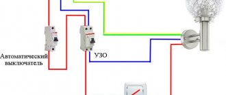
The presented diagram is quite suitable for installing protective equipment in a distribution panel. The PE grounding conductor is indicated by a yellow-green line. The dotted green lines correspond to grounding cables used when connecting complex household devices. As a rule, several machines are used with RCDs. Therefore, the sum of the currents of the circuit breakers must be equal to the sum of the currents of the protective devices.
It is recommended to connect RCDs and automatic machines according to certain rules:
- The RCD should be installed in front of the circuit breaker.
- With a single-phase connection, the power wire is always connected to the top terminal. Installing the power cable from below will damage the device.
- Connecting an RCD to a two- or three-phase network is carried out according to separate circuits, using options with grounding and without grounding.
- During connection, the electrical network must be completely de-energized.
- Ouzo with low ratings, intended for individual lines, cannot be installed in a general network. Under the influence of overloads, the likelihood of current leaks and short circuits increases.
- The connected protective device must be tested. For this purpose, the machine is turned on, on which a certain load is created. If the connected electrical appliance does not cause any changes, then the electrical installation work has been carried out correctly.
How to check an RCD in 30 seconds
The residual current device is responsible for the health and safety of people, so it should be checked periodically for proper operation. For this purpose, the device has a “test” button. If, when pressed, the RCD knocks out, then it is considered to be in good working order.
Machine with “test” button
There is another more reliable verification method. To do this, you need to connect a resistor between the ground and the phase wire of the socket. The resistor resistance is selected based on Ohm's law and the RCD operating current. The method is extremely dangerous for the tester. It is not recommended for use by people who do not have education or experience as an electrician.
Conclusions and useful video on the topic
What is an RCD, why is it needed and how to correctly install this device in a private home:
Rules for choosing RCDs for residential private houses based on differentiated current and length of electrical wiring. Detailed explanation of the process from a professional master:
Installing an RCD in a private home will not require significant material investments from the owners, but will increase the safety of the electrical system, protect residents from electric shocks and burns, and protect the property from fires.
For the device to work properly, it is better to choose a reliable product from a popular brand, rather than a Chinese nameless one. You won’t be able to save money here, but the result of the proprietary module will be many times higher than that of a cheap analogue.
Tell us about how you selected a residual current device for installation in the switchboard of a country house. Share useful information that may be useful to site visitors. Please leave comments in the block below, ask questions, post photos on the topic of the article.
Some tips for choosing
And some recommendations on choosing an RCD. If you plan to install one device at the input, then choose high-quality products from well-established manufacturers. These are companies such as:
- "ABB";
- "Legrand"
- Schneider Electric.
Residual current devices from these manufacturers will cost you about 1800-2000 rubles.
If you want to connect several RCDs and circuit breakers in an apartment (for each outgoing branch), then you will either have to spend a lot of money or choose devices that are a little cheaper. In case of small financial possibilities, opt for RCD or “EKF”, they are slightly inferior in terms of quality and reliability, but also cost much less (about 600-700 rubles).
We have given several options for how to connect an RCD. Choose the one that is most suitable for you, depending on where you live (in an apartment or a private house), what kind of network you have (single-phase or three-phase). Well, decide how many devices you will supply (one at the input or for each consumer group), based on your financial situation.