What is the difference between an automatic protective switch and an input circuit breaker? From a technical point of view, nothing. This is a device designed to automatically shut down electrical networks in case of overload and short circuit. The only difference is in the purpose and connection diagram. If a conventional (group) machine operates within one or several lines, then the input device is responsible for connecting (disconnecting) the entire facility, be it an industrial enterprise or an apartment (private house).
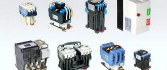
Externally, the input circuit breaker looks like a regular switch.
It can be 1, 2, 3 or even 4 pole, depending on your facility's power supply.
Design and principle of operation
The compact case contains the switching mechanism: two contacts, movable and fixed. When the cocking handle is moved to the working position, the contacts close and are mechanically fixed in the on state.
The circuit through which electric current flows includes two protective devices in series. One is triggered when the set threshold for temperature and current is exceeded (bimetallic plate), the second opens the contacts in the event of a short circuit, or rather, when the current value is significantly exceeded (electromagnetic release).
If the current gradually exceeds the permissible value (indicated on the marking of the machine), the plate heats up and mechanically opens the contacts. When a short circuit occurs, the current increases like an avalanche and activates the electromagnetic release. For multi-pole circuit breakers, it is enough to exceed the parameters on at least one line. The entire package of contacts will be disabled.
In all cases of protection activation, after the danger disappears, the circuit breaker does not return to its original state. A person is required to turn it on.
Types
The machine is selected taking into account the electrical network diagram and its needs. There are single-pole, two-pole, three-pole and four-pole devices.
Single pole
A single-pole switch is used in single-phase electrical networks. Different models have different characteristics, which determine the shutdown speed. The composition includes two release mechanisms - electromagnetic and thermal.
One is triggered when there is a short circuit, the second when the load is exceeded for a certain time. It is connected through the upper terminal, the outgoing wire is connected to the lower one. The principle of operation is the same as that of diverter machines, but the current rating is higher.
Bipolar
Used in single-phase input. The design consists of a block with two poles, which are equipped with levers and a common lock between the shutdown mechanisms. That is, the main difference from a single-pole network is that if there is a problem on any of the lines coming from it, both will be disconnected. Two-terminal networks are used in typical modern apartments.
You cannot replace one double-pole switch with two single-pole circuit breakers! This is prohibited by the PUE.
Three-pole
For three-phase networks, three-terminal and four-terminal networks are used. Such electrical networks are found in homes where food is cooked on electric stoves. To connect a three-pole circuit breaker, each terminal is connected in phase. In devices with four poles, a neutral wire is additionally used.
When installing it yourself, the ground (not the neutral) should never pass through the machine.
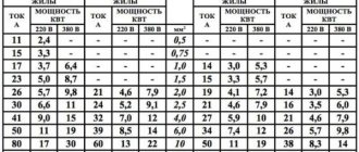
How to choose a machine based on current strength
We already know that all the electrical current to power the object will flow through this switch. According to Ohm's law, it is clear that the load must be summed up based on all consumers in the house (apartment). Calculating this value is quite simple.
Tip: It is not necessary to calculate energy consumption by summing up the power of all electrical appliances.
Of course, you can turn on the boiler, electric oven, air conditioner and iron at the same time. But such a “celebration of life” will require powerful electrical wiring. And the technical conditions for such input power will cost significantly more. For energy supply organizations, tariffs for coordinating connections grow linearly depending on the number of kilowatts.
For a typical apartment, we can assume the simultaneous operation of a refrigerator, TV, computer, and air conditioner. In addition to them, it is permissible to turn on one of the powerful appliances: a boiler, an oven or an iron. That is, the total power of electrical appliances will not exceed 3 kW. We don’t take lighting into account; today, every home has energy-saving lamps.
This is interesting: if you go back 20–30 years ago, when each chandelier had only incandescent lamps, a two-room apartment with full lighting could spend 500–700 W on light alone.
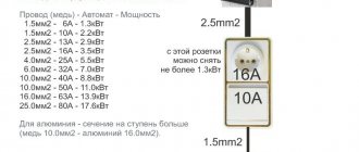
Usually, for a power reserve (force majeure circumstances are possible), 20–30% is added to the calculations. If you forget to turn off the boiler and start using the iron while the air conditioner is running, you won’t have to run to the electrical panel to restore the power supply. It turns out: 4 kW divided by 220 V (according to Ohm’s law), current consumption 18 A. The nearest circuit breaker is rated 20 A.
For reference: most manufacturers of electrical products produce circuit breakers with the following operating current ratings:
2 A, 4 A, 6 A, 10 A, 16 A, 20 A, 25 A, 32 A, 40 A, 50 A, 63 A...
The marking is in the product passport, and always on the body.
When selecting a device more accurately, especially when used in conjunction with a non-standard load (motors or other loads with significant starting currents), it is necessary to make a choice not only by the rated current, but also by the time-current characteristic.
For example, the input circuit breaker shown below in the picture has a rated current of 16A and a characteristic of type “C” (type “C” is well suited for the usual standard load - our apartments).
We will tell you more about the time-current characteristic below.
We are not interested in higher currents, this exceeds the power of 15 kW. No one will approve such a connection to your apartment. Typically, residential input is limited to automatic machines with an operating window of about 32 A.
For a private home, the figures may be higher. The calculation takes into account the increased living space, the presence of outbuildings with power supply, a garage, a workshop, and powerful power tools. An input circuit breaker for supplying power to a private house usually has an operating current of 50 A or 63 A.
Why is a short circuit dangerous?
This situation can arise during repairs if an electrician accidentally shorts the neutral and phase wires together, or due to the destruction of insulation in an adapter box or some electrical appliance.
In this case, the current flowing in the wires can grow to a very large value, limited only by the resistance of the wires and the capabilities of the line. In this case, the current-carrying conductors heat up to the temperature at which the insulation ignites, which can lead to a fire, so it is necessary to immediately turn off the power to the line.
What other parameters are important when choosing
Number of poles
For ease of understanding, we will put three-phase switches out of brackets. We choose between 1 and 2 pole designs. From the point of view of the Electrical Installation Rules (PUE), there is no difference. But the same rules imply high-quality organization of grounding or grounding. And if a problem arises with the appearance of a phase at zero (unfortunately, this is real in old housing stock), then it would be better to completely disconnect your apartment from the power lines. Therefore, if you can choose which input circuit breaker to install, take a two-pole one.
Important: this connection is suitable for the TN-S grounding system. If you have a TN-C circuit in your house, you can install a single-pole circuit breaker.
Time - current characteristic
There are different types of time-current characteristics curves, they are designated by Latin letters: A, B, C, D... Starting from A onwards, the sensitivity of the device gradually becomes rougher. For example, type “B” means operation of the electromagnetic release at 3–4 times the current, type “C” at 5–7 times, “D” at 10 times. The thermal release will operate in the same way for different types of time-current characteristics.
More accurate data should always be obtained from the manufacturer’s documentation for each specific product, for example, for BA47-29 incoming automatic machines the response characteristics are as follows:
An example of graphs for BA47-29 with characteristics (types) B, C, D are shown below in the picture, dependencies for other types can be found on the official websites class=”aligncenter” width=”1152″ height=”556″[/img]Selection of one type or another is determined by the type of load being connected, or more precisely by its ability to consume current intermittently. For example, motors have a starting current several times higher than the rated current, and depending on their types, type “C” or “D” devices can be used. Type “B” is recommended for loads that do not have significant inrush currents.
Also, the use of types with reduced sensitivity of operation makes sense to increase the probability of operation of lower groups of circuit breakers.
Rated current
The main characteristic on which the device is mainly selected. However, as we saw in the previous section, it is also necessary to take into account the time-current characteristic, since the actual operation current depends simultaneously on both the rated current and the type of characteristic. In the previous tables, the rated current is indicated as In. Theoretically, in the absence of inrush currents, a load consuming a current equal to the rated one should not lead to operation (shutdown) of the device.
Mounting method
Today, there is no alternative. These are switches that are mounted on a DIN rail. No direct screwing to the wall or panel body. DIN mounting only. However, with the use of special accessories, other types of fastening are possible.
The device can be in a separate housing, or installed in a common panel - it doesn’t matter. The main thing is to provide free access for the owner. An important point: sealing the input machine. There are many ways to restrict access to contacts (to prevent unauthorized connections). You can install plugs on the holes to tighten the screws on the contacts.
Or simply put seals on the covers covering the contact groups.
The main thing is that after sealing you can easily turn on and off the power supply.
Number of poles
Depending on the number of poles, the machines are:
- Single-pole (1p, 1p). This is the most common type. It stands in a circuit and protects one wire, one phase. This is shown at the beginning of the article.
- Bipolar (2p, 2p). In this case, these are two single-pole circuit breakers, with a combined switch (handle). As soon as the current through one of the machines exceeds the permissible value, both will turn off. These are mainly used to completely disconnect a single-phase load when both the zero and the phase break. It is the two-pole circuit breakers that are used at the entrance to our apartments.
- Three-pole (3p, 3p). Used to break and protect three-phase circuits. Just as in the case of two-pole ones, these are actually three single-pole circuit breakers, with a common on/off handle.
- Four-pole (4p, 4p). They are rare, they are installed mainly at the input of three-phase switchgears (switchgears) to break not only the phases (L1, L2, L3), but also the working zero (N). Attention! Under no circumstances should the protective grounding (PE) wire be broken!
What does energy sales think about this?
Let's say you have organized exemplary electrical wiring in the house, calculated each consumer to the nearest ampere, and want to get a certain current load at the input. And when you contacted power engineers, you were refused. You should know that the energy sales company is not interested in which input machine you choose. They have limits on the electrical supply line, or the nearest transformer substation. And no one has the right to exceed these standards: otherwise it will not be possible to connect the next people who want to, or the entire line will operate in constant overload mode.
Therefore, before planning the energy supply scheme for your home, visit the organization that will supply you with electricity.
Time-current characteristics
Obviously, the machine does not always turn off instantly, and sometimes it needs to “think and make a decision”, or give the load a chance to return to normal.
The time-current characteristic shows after what time and at what current the machine will turn off. These characteristics are also called tripping curves or current-time characteristics. Which is more precise, since it depends on the current after what time the machine turns off.
Tripping curves or current-time characteristics
Let me explain these graphs. As I said above, the circuit breaker has two types of protection - thermal (against overcurrent) and electromagnetic (against short circuit). In the graph, the operation of thermal protection is a section that smoothly descends. Electromagnetic – the curve abruptly breaks down.
The thermal one works slowly (for example, if the current is twice the nominal value, the machine will go out in about a minute), and the electromagnetic one works instantly. For graph B, this instant “begins” when the current exceeds the nominal value by 3-5 times, for category C - 6-10 times, for D (not shown, since it is not used in everyday life) - 10-20 times.
How it works - you can imagine what will happen if the current exceeds the nominal value by 5 times, and the protection is with the “C” characteristic, as in all houses. The machine will only go off after 1.5-9 seconds, depending on your luck. In 9 seconds the insulation will melt and the wiring will need to be changed. In this case, therefore, short circuit is better than overload.
You want to change the parameters of the input switch (if it is knocked out)
One of the reasons is that your input circuit breaker is constantly knocked out at the same time as the internal circuit breaker in the distribution panel. And this didn’t happen before. Why is this happening? There are switches on the home panel with a similar maximum current value. For example, you had a 25 A ceramic fuse in your entrance (an old house). After repairs, it was replaced with a modern 20 A circuit breaker. And the distribution switches in the apartment have the same rating. It would seem easier to replace the machine at the entrance, and everything will fall into place. However, this is fraught with a fine from the energy supply company.
We will have to redo the home panel and install group circuit breakers with a lower value.
Download
For those who are interested in the topic deeper and more thoroughly, I am posting GOST, which describes in detail all the characteristics and terminology of circuit breakers.
• GOST R 50345-2010 / GOST R 50345-2010 (IEC 60898-1:2003) Small-sized electrical equipment. Automatic switches for overcurrent protection for household and similar purposes. Part 1. Circuit breakers for alternating current. This standard applies to air circuit breakers (hereinafter referred to as circuit breakers) for alternating current for operation at a frequency of 50 or 60 Hz with a rated voltage (between phases) of not more than 440 V, a rated current of not more than 125 A and a rated breaking capacity of not more than 25,000 A. , pdf, 1.89 MB, downloaded: 1057 times./
• Kharechko V.N., Kharechko Yu.V. Automatic switches of modular design / Kharechko V.N., Kharechko Yu.V. Automatic circuit breakers of modular design: Reference manual. The reference manual sets out the requirements of GOST R 50345-99 (IEC 60898-95) for household circuit breakers intended for overcurrent protection, examines the design of circuit breakers, gives characteristics and their classification. Errors are analyzed that are partially corrected in the new version of GOST R 50345-2010, pdf, 7.17 MB, downloaded: 1062 times./
As always, I will be glad to have questions and comments on the article in the comments!
Switching circuit of the introductory machine
In addition to the main task (ensuring electrical safety), the input switch is designed to disconnect the consumer from the power supply for work. For example, metering device maintenance. Therefore, in most cases the machine is installed in front of the electric meter.
This is the area of responsibility of electricians; the owner of the apartment (household) has no right to interfere. For apartment buildings - this is an entrance shield, for a private house - a pillar, fence, or outer wall of the household. This scheme is used in 90% of residential properties. Between the sealed input machine and the metering device (which also has seals), there is no access for unauthorized connection. This is done to prevent illegal extraction of electricity. Many homeowners install a duplicate input circuit breaker for ease of maintenance and repair of the distribution panel. It is connected between the energy meter and group circuit breakers, and is mounted inside the panel of the apartment (household).
How to choose the right automatic backup machine?
The optimal solution is that the protection current should be less than at the input device and greater than at the group switches. For example, a 32 A circuit breaker is installed at the input, and group circuit breakers are installed at 20 A. This means that the backup must operate at a load current of 25 A. If such a ratio cannot be achieved, the current cutoff of the backup must correspond to the input circuit breaker. In this case, it simply acts as a disconnecting device (for carrying out work). And in an emergency, it will operate simultaneously with the input device.
Weak link protection
So, we are convinced that the calculation of the circuit breaker should be made based not only on the total power of the devices included in the circuit (regardless of their number), but also on the cross-section of the wires. If this indicator is not the same along the electrical line, then we select the section with the smallest cross-section and calculate the machine based on this value.
The PUE requirements state that the selected circuit breaker must provide protection for the weakest section of the electrical circuit, or have a current rating that will correspond to a similar parameter for the installations connected to the network. This also means that the connection must be made using wires with a cross-section that can withstand the total power of the connected devices.
How to select the wire cross-section and rating of the circuit breaker - in the following video:
If a careless owner ignores this rule, then in the event of an emergency that arises due to insufficient protection of the weakest section of the wiring, he should not blame the selected device and scold the manufacturer - only he himself will be to blame for the current situation.
Table of automatic switches
Devices for shutting off electricity during overloads and short circuits are installed at the entrance to any home network.
It is necessary to correctly calculate the current ratings of circuit breakers, otherwise their operation will be ineffective: either they will not protect lines and household appliances, or false alarms will often occur.
Performance
Its service life largely depends on how quickly the switch turns on and closes its contacts. However, is it possible to determine at home how well your device corresponds to this parameter without disassembling the case itself and without resorting to specialized laboratory tests?
Of course you can. Everything is done very simply. Take a regular battery-powered indicator screwdriver. Exactly with the battery.
It is usually used for testing and determining the integrity of the circuit. Although knowledgeable people use this useful device in many other ways. Read about which ones in a separate article.
Use the tip of a screwdriver to touch the upper contact, pressing the metal patch on the handle from above, and with the finger of your other hand, touch the lower contact of the switch.
After which, you slowly begin to turn on the machine, cocking the tongue.
The contact should appear (the LED in the screwdriver will light up) only at the very last moment, when the device has already clicked.
If the same manipulation is done with another switch, the light comes on when the power lever reaches the middle of the stroke.
It turns out that the device is not yet cocked, but the contacts are already closed. This is what this sometimes leads to under heavy load (view of the contacts from inside the machine):
This ultimately affects the rapid wear and burnout of contacts. While the quick-start mechanism increases the service life of the product by almost 30%.
How do I convert the amp rating of a circuit breaker into power?
This technique is necessary when you know the power of all household appliances that will be connected to the network under the circuit breaker. Manufacturers indicate it in watts (W), so the performance characteristics of the circuit breaker and network parameters are brought to a unified measurement system. The formula used for this is:
P = U*I, where
- P – power value;
- U – supply voltage rating;
- I – current value.
If the calculation is made for a three-phase network circuit breaker, where there are three phases at once, then the power value is calculated using a modified formula, since the value will increase by a constant:
Correct terminals
If you look at individual brands of machines, you can see that if the terminal is not completely open, the wire can accidentally get into the terminal space.
When you connect wires in a panel at a height, you usually do not see the top terminal and the core is inserted there, as they say, by touch.
An electrician who tightens a terminal with an incorrectly inserted wire will not feel anything. There seems to be an effort, which means the tightening was successful.
Some even check this tightening torque using a torque screwdriver scale.
In fact, the wire will not be secured.
In good circuit breakers, such an oversight or error is simply impossible. In them, as soon as you begin to tighten the terminal, the terminal space is immediately closed with a special plate.
It can be either metal or plastic.
Another recommendation, but not a mandatory feature regarding the terminals, is an additional connector for a comb busbar.
When a number of machines are assembled in an electrical panel, they are connected to each other through just such a bus. It is very convenient and reliable.
But the problem arises if you later need to make some kind of desoldering and bring out a separate wire from this terminal.
The contact density changes, it is not fully pressed and gradually burns out. As a result, the machine has to be replaced.
So, in some models (mainly from ABB), there is an additional connector for this purpose, designed specifically for the comb bus.
The main contact remains free and you can safely connect the cable core to it without compromising the reliability of the connection.
Also look for notches on the terminals. It is advisable that they are not smooth.
With these notches, the terminal material bites into the copper core, thereby promoting better transient resistance.
Also make sure that the plastic near the screw does not come apart when tightening. You can check this right in the store using screwdrivers.
Insert the tip of one screwdriver into the terminal, and with the other forcefully tighten the contact. Next, watch how the two halves of the housing behave near the clamp.
If they crawl to the sides and a fairly visible gap appears, this is a reason to think about such a purchase.