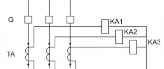
Conditional diagram of differential protection
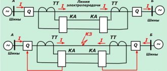
If we take the protected object as a node (Fig. 1.1) and record the current on all branches connecting the protected object (node) with the external network, then if there is a fault on the outgoing branch, the sum of the currents entering and leaving the node will be equal to zero.
Rice. 1.1. Differential protection circuit with circulating currents
If the protected object is damaged (short circuit in the node), the sum of the currents along the branches will be equal to the short circuit current.
According to the diagram in Fig. 1.1 in normal load mode and during an external short circuit (on the outgoing branch, behind the current transformer towards the network), currents equal to the secondary currents of the CT circulate in the auxiliary wires connecting the secondary windings of the current transformers.
Therefore, this implementation of longitudinal differential protection is called a circuit with circulating currents. Another embodiment of the differential principle (Fig. 1.2) is a circuit with balanced voltages, in which the secondary windings of the CTs are connected to each other in series, and a reacting element (differential relay) is included in the same circuit. It is believed that the identical ends of the primary and secondary windings of the CT are located on the same side. The current in the relay will be equal to:
| (1–1) |
where Z is the sum of the resistances of the auxiliary wires, relay windings and CT windings.
Rice. 1.2. Balanced voltage differential protection circuit
In normal mode and short circuit outside the range of E1 = E2 and directed in opposite directions, the current in the relay is zero.
If there is a fault in the protected area E1 ≠ E2, but directed in one direction, the current in the relay is not zero and, if it exceeds the operation current, the protection will turn off the damaged element.
In a circuit with balanced voltages in normal mode and external short circuits, there is no current in the secondary windings of the CTs, and the CTs operate in no-load mode. This can lead to unacceptable overheating of the CT and the appearance of high voltages in the secondary circuits, therefore, a balanced voltage circuit with standard current transformers according to Fig. 1.2 does not apply; special intermediate CTs are usually installed. In addition, the circuit requires the use of CTs that are as close in characteristics as possible. Thus, the circuit with balanced voltages is more complex than with circulating currents, and therefore it has received limited use.
In turn, the circuit with circulating currents can be implemented in two versions: with low resistance and with high resistance of the differential relay circuit.
The advantage of a low-resistance differential relay circuit is the shunting of the measuring CTs, which eliminates their influence on each other as much as possible.
The advantage of a circuit with a high resistance of the differential circuit is the automatic hardening of the protection when any CT is saturated during an external short circuit, since in this case the low resistance of the magnetization branch of the saturated CT shunts the differential circuit, reducing the unbalance current (voltage).
Most often, a circuit with a high resistance of the differential circuit is used when performing differential protection of buses, where deep saturation of the CT is possible at the connection where the external short circuit for differential protection occurred and in sensitive differential protection against ground faults. Currently, due to the reduction in costs for the implementation of complex algorithms when switching to the electronic element base of relay manufacturing, a high-resistance circuit is being replaced by low-resistance differential relay .
When considering the principle of operation of differential protection, it was accepted that in load mode and in external short circuit mode, the current in the differential circuit is zero. This is only possible if the secondary currents of the CTs are exactly equal to the primary reduced currents, i.e.
In reality, a current flows in the differential circuit in these modes, called unbalance current.
Let us determine which components make up the unbalance current.
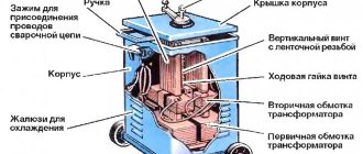
Design of ZON-110
The ZON design consists of a cylinder onto which the base is attached. The base is a small part in the form of an angle on which the entire structure is fixed. A static contact is connected to it with a device consisting of a pipe (mostly aluminum) onto which a round plate with a shaft is attached. This device is called a grounding knife. The knife is connected to the phase wire of the line, which enters the grounding phase at the second end.
The pressure of the entire installation is set and regulated by a steel spring. Valve arresters, devices protecting the installation from overvoltage. They take the brunt of the storm during a thunderstorm. The appearance resembles a metal caterpillar. The 110 kV ZON is switched on between the zero voltage point and ground, or directly through a transformer with a secondary winding.
CT error in the operation of transformer differential protection
This component of the unbalance current is characteristic of all differential protection and is caused by the fact that the secondary current is equal to:
| (1 – 2) |
where Isecond. – CT secondary current; I'first – primary current reduced to the secondary winding; I'us. – magnetizing current reduced to the secondary winding. The current in the relay - unbalance current - is equal (for differential protection with two branches):
| Iр.=Inb.=Isecond.1 – Isecond.2 = I’first.1 – I’name.1 – I’first.2 + I’name.2, | (1 – 3) |
where Isecond.1, I'primary.1, I'nam.1 – secondary, reduced primary and reduced magnetizing current of the CT of the first branch; Isecond.2, I'first.2, I'nam.2 – the same for the second branch. Provided that the primary currents of the protected object are equal to the primary currents of the CT in case of an external short circuit: The unbalance current will be equal to:
| (1 – 4) |
In the general case, the unbalance current is equal to the geometric sum of the magnetizing currents of all branches of the differential protection:
| (1 – 5) |
In order to identify the influence of CT loads and differential relay resistance on the unbalance current, we will draw up an equivalent circuit for differential protection [3]:
Rice.
1. 3. Equivalent circuit of differential current protection In Fig. 1. 3. the following designations have been introduced: Z'first1, Z'us1, Zsecond1 – reduced resistance of the primary winding and magnetization branch, resistance of the secondary winding of the CT of the first branch; Z'first2, Z'us2, Zsecond1 – the same for the second branch; I'first1, I'us1, Isecond1 – reduced primary current, magnetizing current and secondary current of the CT of the first branch; I'first2, I'us1, Isecond1 – the same for the second branch; IP, ZPO – current in the differential relay circuit and resistance of the differential relay; rpr1, rpr2 – resistance of connecting wires from the CT to the differential relay for the first and second branches.
Assuming that all resistances in Fig. 1. 3 are linear elements and having compiled equations for this circuit according to Kirchhoff’s laws, we obtain for Inb with an external short circuit, when I'first1 = I'first2:
| (1 – 6) |
where Z2 = Zsecond2 + rpr2; Z1 = Zsecond1 + rpr1; Z'us1 • Z'us2 = Z' 2us; Z'us1 + Z'us2 = 2Z'us. Analysis of formula (1 – 6) shows that in order to reduce the unbalance current it is necessary for less powerful CTs (having lower magnetization resistance) to reduce the external load.
Unfortunately, for most transformers with a star-delta winding connection circuit, especially for less powerful CTs, on the star side the load must be increased three times due to the CT connection in a delta, which leads to a large CT error , to an increase in the unbalance current and, accordingly, to an increase in the operating current of the differential protection .
In transient operating modes, unbalance currents can be many times higher than the steady-state values. The conducted studies have shown that the transient unbalance current can contain a significant aperiodic component, and if the resistance of the arms is equal and the current-voltage characteristics of the CT are identical, the unbalance current represents a unipolar signal.
If the resistance of the CT arms is unequal, negative half-waves appear in the unbalance current [4]. The transition process is significantly influenced by the time constants of the primary and secondary circuits - with their increase, the unbalance currents increase, and the transition process itself is delayed.
To ensure the correct functioning of the differential protection, it is necessary to adjust the protection response current from the unbalance currents caused by the CT error in the maximum external short circuit current mode.
Due to the complexity of calculations for real CTs of transient unbalance currents, the operating current of differential protections is selected according to the condition of detuning from the steady-state unbalance current, and the transient mode is taken into account by introducing an increasing coefficient kper, which determines the degree of constructive detuning of the differential relay from the transient mode (relays with intermediate saturable CTs, relay with time-pulse circuit, etc.).
For differential protection, in which CTs of several sides of the protected object are combined, the unbalance current caused by CT errors is determined in the mode when the CTs of one side operate with an acceptable error, and the CTs of the other - without error.
In this case, the difference in current between the sides will flow in the differential circuit and determine the unbalance current.
The maximum permissible total error of the CT for differential protection in the steady state of the maximum external short-circuit current should not exceed 10%.
If CTs of the same type are used for differential protection, with the same transformation ratio, operating under approximately the same conditions, then it is unlikely that the error, on the one hand, will be equal to the permissible one, and on the other hand, will be equal to zero. To take into account such operating conditions of the CT (in the formula for determining the unbalance current), a CT uniformity coefficient of 0.5 is introduced.
Thus, the component of the unbalance current caused by the CT error is determined by:
| (1 – 7) |
where kper is a coefficient taking into account the transition mode; kodn – CT uniformity coefficient, which is taken equal to 1.0 or 0.5 depending on the CT operating conditions; ε – total error of the CT in steady state at the design current of the external metallic fault; ISC max – maximum current value for a stable external metallic short circuit.
Protection with an operating current selected according to the condition of detuning from unbalance current according to (1–7) does not provide the required protection sensitivity, therefore various methods are used to increase sensitivity and detuning from unbalance current. The traditional way to tune out unbalance currents is percentage braking, which means an increase in the operating current of the differential relay with an increase in the braking current. As the braking current, you can use the phase current of one or more protection sides, half the sum of the absolute values of the protection side currents, etc.
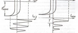
How the process works
When a load is applied, the magnetization of the device due to switching on is considered as a negative phenomenon that can provoke a BTN of maximum amplitude. When turned off, the magnetizing current is reduced to zero, and the magnetic induction is adjusted depending on the degree of magnetization of the steel core, as a result of which residual induction remains in the magnetic circuit.
If after a while the current-converting device is switched on again under a voltage subject to the sinusoidal law of change, the magnetic induction changes with a displacement of the residual value up to 90% of the nominal value. The result is a high magnetization amplitude and a change in the shape of the curve.
Rice. 3. Classic type BNT curve
The magnetizing current level decays within tenths of a second, but complete “smoothing” of the curve occurs within a few seconds, and under certain conditions – after a few minutes. The duration of attenuation of the aperiodic component of the BTN oscillogram is due to the high amplitude of the current at the initial (zero) moment of time and the content of various harmonics. The peak value depends on the load voltage and its parameters, as well as on the value and polarity of the residual magnetic flux in the core.
The current peak can be 10-15 times higher than the rated value for high-power units, and for devices with a power of (
Compensation of angular shifts of primary currents and elimination of zero-sensitivity currents
For power transformers with a star-delta connection, there is an angular shift between the higher and lower voltage currents with a factor of 300. Without measures to compensate for this shift, a significant coarsening of the differential protection for the operating current would be required. Therefore, the angular shift of the primary currents is compensated by a corresponding rotation of the secondary currents on one side of the transformer.
The primary rotation of currents occurs due to the connection of the transformer windings in a “triangle”. Therefore, to compensate for the phase error, the current transformers are also connected in a triangle.
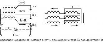
Theoretically, it makes no difference on which side the current transformers are connected in a “triangle”. However, for a power transformer with a grounded zero point on the star side, in the event of an external fault, zero-sequence currents flow to the ground from the neutral side - the neutral “generates” zero-sequence currents. These currents are transformed into the secondary circuit on the higher voltage side, and on the delta side there are no currents in the current transformers, since the primary zero-sequence currents circulate inside the delta winding and do not go out into the external circuit. Thus, all the zero-sequence current from the star side of the transformer will flow into the differential circuit.
To prevent false triggering of differential protection, it is necessary to suppress zero-sequence currents in the differential circuit.
Connecting current transformers on the “star” side of a power transformer in a “delta” provides, on the one hand, compensation for the angular shift of the primary currents and, on the other hand, the absence of zero-sequence current in the differential circuit due to the fact that zero-sequence currents circulate inside the circuit “ triangle" current transformers.
It should be noted that connecting current transformers in a “triangle” increases the load of the secondary circuit three times , which can lead to an increase in the error of the current transformers, the need to increase the cross-section of control cables, replace current transformers, etc.
In modern digital differential protection, compensation for the angular shift of currents and the exclusion of zero-sequence currents is provided by software, which makes it possible to connect current transformers in a “star” on all sides of the power transformer.
Interesting video about power transformer protection:
Installation
Installation at power plants, regardless of the type of ZONE, is carried out according to the following algorithm:
- Preparation of structural planes for installation of supports. They must be even, as slight unevenness increases the risk of malfunctions.
- Then the ground electrode is installed on the previously prepared surface.
- Fasteners must be installed tightly in the special holes.
- After this, they must be tightened tightly.
- Then the drive is installed. It is attached to the ZONE of the transformer by welding the ends of the rod with the axle and insert.
- Adjust the insulating distance with a pull rod. It should be equal to 8.9 cm or more.
- Carry out a test run of the ground electrode.
- Connect the supply busbar to the grounding terminal.
- Then you need to remove dust from the insulator. For this, regular paint thinner is often used.
- After installation is completed, the installation seams are sanded and painted.
- Then all connections are treated with lubricant.
Different TT coefficients in DZT
To equalize the secondary currents on different sides of the power transformer, it is necessary that the rated primary currents of the power transformer be equal to the rated primary currents of the CT, and when connecting the CT in a “delta”, the rated primary current of the CT is √3 times less than the rated current of this side of the power transformer.
CTs have a standard scale of nominal values, therefore, to equalize secondary currents on different sides of the transformer, intermediate autotransformers (transformers) or magnetic equalization are used by connecting secondary current circuits to different numbers of turns.
However, all these methods do not allow the secondary currents to be accurately balanced (impossibility of setting a fractional number of turns or due to the discreteness of the taps of the winding turns, etc.), so an additional component of the unbalance current appears . This component is determined:
| (1 – 8 ) |
where Wcalc is the calculated number of turns; Wust – the set number of turns. The estimated number of turns is determined by the expression:
| (1 – 9) |
where Wosn and Inom. main – number of turns and rated current of the side of the protected transformer, taken in the calculation as the main one; Wcalc and Inom – the calculated number of turns and rated current of the side of the protected transformer, taken in the calculation as the non-main one.
It should be noted that in modern digital relays it is possible to minimize this component of the unbalance current (to a level of ≈ 1%).
Adjusting the transformation ratio of power transformers
The equalization of secondary currents of CTs is carried out at one specific transformation ratio of the power transformer (at the nominal or optimal position of the regulator). When the position of the voltage regulator changes, the equality of currents (ampere-turns) is violated.
Another component of the unbalance current appears in the differential circuit, which is determined by the formula:
| (1 – 10) |
where Δu is the relative maximum change in the power transformer coefficient from the nominal (optimal) value.