Types of measurement
The schematic diagram for removing the current-voltage characteristic looks like this (Fig. 1):
Rice. 1. Scheme for measuring current-voltage characteristics of current transformers
Testing of current transformers is regulated by the following standards:
GOST 7746-2001 [1] does not classify the removal of the entire I-V characteristic as a mandatory check of the CT, but regulates the determination of the magnetizing current of the secondary winding, measured when a voltage is applied to it, determined by a special formula. According to clause 9.8 of GOST 7746-2001 “Determination of magnetizing current of secondary windings”, the voltage of the secondary winding must be measured with a voltmeter with a basic error of at least ±1%, responding to the average voltage value, and the readings must be multiplied by the shape factor for a sinusoidal signal equal to 1.11. The effective value of the magnetizing current should be measured with an ammeter with an accuracy class of at least 1%.
According to clause 7.4 “Removing the magnetization characteristics” RD 34.45-51.300-97 “Scope and standards of testing of electrical equipment” [2] allows both the removal of the current-voltage characteristic before saturation begins (but not more than 1800 V), and the removal of 3 control points. The recorded characteristic (control points) is compared with the typical magnetization characteristic or the characteristics of serviceable transformers of the same type. In this case, the difference from the values measured at the manufacturer or from those measured on a working CT is allowed, no more than 10%.
Direct verification method
Direct testing is the most proven method, also called load testing of the circuit.
To carry out this, you should use the standard circuit for switching on the transformer in the circuits of the primary and secondary equipment, or assemble a new circuit for testing, in which a current of 20 to 100% of the rated value passes through the primary winding of the transformer and is measured in the secondary.
The numerical value of the measured primary current must be divided by the numerical value of the measured secondary winding current. The resulting value will be the transformation coefficient, which should be compared with the passport value, which will allow us to judge the serviceability of the transformer.
A current transformer may contain not one, but several secondary windings. Before testing begins, all windings must be securely connected to the load or short-circuited. Otherwise, in the open secondary winding, provided that current appears in the primary winding, a voltage of several kV will arise, which is dangerous to human life and can lead to equipment damage.
The magnetic cores of most high-voltage current transformers require grounding. For this purpose, their design provides a special terminal, which is marked with the letter “Z”.
In practice, very often there are some restrictions on testing transformers under load, due to the characteristics of operation and test safety. In this regard, other verification methods are often used.
Testing current transformers using the RETOM-21 complex
Construction of current-voltage characteristics of current transformers
Construction of the current-voltage characteristic (CVC) is one of the important stages of testing current transformers (CTs). The current-voltage characteristic represents the dependence of the voltage of one of the secondary windings on the magnetizing current from the same or another winding at XX on the primary winding of the CT (Figure 1). The current-voltage characteristic is measured in the range from zero to several times the current of the beginning of saturation of the transformer magnetic circuit, while the voltage on the secondary winding should not exceed 1800 V in order to avoid damage to its insulation. The taken characteristic is compared with the typical magnetization characteristic or with the magnetization characteristics of serviceable CTs of the same type as the one being tested, most often with the characteristics of CTs of other phases of the same connection.
The main task of constructing a current-voltage characteristic is to determine the transfer characteristic of a CT, which allows one to calculate the maximum permissible load connected to the secondary winding of the transformer. When the CT magnetic circuit is saturated, a significant change in the signal shape occurs, which can lead to large errors in the transmission coefficient, and the higher the current, the greater the error. Therefore, when calculating the settings of relay protection and automation devices connected to the CT, it is necessary to know when the transformer operates in the linear section of the current-voltage characteristic (section ab Figure 1), and when in the section whose deviation from the linear exceeds 10% (section bc in Figure 1) at the moment the onset of saturation of the magnetic circuit. In the last section of the current-voltage characteristic, operation of the transformer is not recommended. Thus, the maximum load connected to the secondary winding of the CT is calculated based on the fact that the transformer must operate in the linear section of the current-voltage characteristic.
Rice. 1. Typical current-voltage characteristic of a CT
When taking the current-voltage characteristic, the presence of short-circuited turns can be revealed - one of the most common damage to CTs. This type of damage can be identified by a sharp decrease in the current-voltage characteristic and a change in its slope. It should be noted that other tests, such as the transformation ratio test, do not detect this.
It is worth highlighting a number of requirements for the testing equipment used to construct the current-voltage characteristics of transformers:
1. The voltage source must have high power.
Obviously, the more powerful the voltage source when taking the characteristics, the more stable the sinusoidal voltage and the more reliable the results.
The RETOM-21 device uses a powerful voltage source U3, capable of delivering voltages up to 500 V and a power of up to 3 kVA. Using this source, you can test CTs for voltages from 0.4 to 35 kV with a saturation voltage of the magnetic circuit up to 500 V. The source is regulated using a LATR made of high-quality materials, which allows you to obtain the minimum possible distortion of the signal shape.
In 2010, the scientific and production enterprise "Dynamics" began serial production of the RET-VAKH-2000 unit, which replaced the previously produced RET-VAKH unit. The new unit has significantly expanded the capabilities of the RETOM-21 device. With its help, you can obtain voltages up to 2000 V. The power that the unit is capable of transmitting is 2 kVA, which allows you to output a sinusoidal signal to current transformers for voltages up to 750 kV. It is necessary to take into account that the internal saturation of the internal transformer of the RET-VAKH-2000 unit occurs at a voltage of 2100 V. This means that there is no distortion of the output signal over the entire operating voltage range of the unit. This feature of RET-VAH-2000 eliminates the occurrence of additional errors when plotting the I-V characteristic.
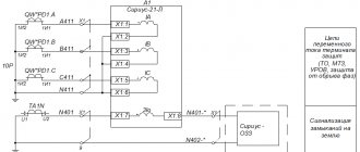
An example of a diagram for connecting a current transformer to a RET-VAKH-2000 unit is shown in Figure 2.
Rice. 2. Connection diagram of the current transformer to the RETOM-21 complex
2. The meter must respond to rms current and voltage values.
When taking the current-voltage characteristic in the saturation region of the transformer magnetic circuit, the shape of the voltage and current signal is distorted. If, under such conditions, a device that responds to the average rectified value of the input parameters is used as a meter, the current-voltage characteristic turns out to be overestimated due to the influence of the signal shape on the accuracy of the readings. Devices that respond to root mean square values (True RMS) do not have such disadvantages.
The RETOM-21 device has the ability to measure root-mean-square (True RMS), average-rectified and amplitude values of currents and voltages. This allows you to build the current-voltage characteristics of transformers without additional errors that may arise due to the non-sinusoidal nature of the measured parameter.
The device provides the ability to recalculate currents and voltages taking into account the transformation ratio of the RET-VAKH-2000 block, which allows you to display the real voltage and current supplied to the transformer winding on the meter screen.
3. Removing the current-voltage characteristic should not affect the further operation of the CT.
If, when removing the current-voltage characteristic of the CT, the supply of voltage is stopped at a point of the sinusoid other than zero (Figure 3), then residual magnetization may appear on the magnetic circuit of the transformer.
Rice. 3. Incorrect disconnection of the voltage source
The presence of residual magnetization (point 1 in Figure 4) can lead to incorrect operation of the transformer when subsequent current is applied.
Rice. 4. Hysteresis loop of the CT magnetic circuit
The output of signals in the RETOM-21 device is designed in such a way that the voltage source of the RETOM-21 device is turned off when the input voltage sinusoid passes through zero (Figure 5), which in turn eliminates the possibility of residual magnetization.
Rice. 5. Correct source shutdown
Determination of unipolar terminals of the primary and secondary windings
The RETOM-21 device can be used to determine the polarity of transformer windings. At the beginning of the test, it is necessary to assemble the circuit shown in Figure 6.
Rice. 6. Diagram of connecting the CT to the RETOM-21 device to determine the polarity of the windings.
Current is supplied to the primary winding of the transformer from source I5, the secondary winding is connected to an external ammeter built into the device. Using a phase meter, the angle between the currents of the primary and secondary windings is determined. If the angle between these two currents is close to zero, then unipolar windings are selected, if the angle is close to 180 degrees, multipolar windings are selected. To check the polarity of the windings of small transformers, you can also use the RETOMETER-M2 volt-amperephase meter.
Checking the CT transformation ratio
Depending on the class of the transformer, measurement of the transformation ratio can be carried out either using output U5 (maximum current up to 750 A) of the RETOM-21 device (Figure 
Rice. 8. Connection diagram of CT to output U5 to check the transformation ratio
or using a PET-3000 current transformer connected to source U6 (Figure 9). In this case, to measure the primary current, a RET-DT unit is used, capable of measuring currents up to 30 kA.
Rice. 9. CT connection diagram for checking the transformation ratio
Electrical Strength and Insulation Resistance Test
Testing of electrical strength and insulation resistance can be carried out using the RETOM-6000 device, which produces direct and alternating voltage up to 6 kV.
This device provides the ability to measure leakage currents, ohmic insulation resistance, as well as plot the I-V characteristics of current transformers.
Thus, the RETOM-21 complex allows for full testing of current transformers, providing a number of advantages:
– labor costs and inspection time are reduced;
– the ability to check any TT;
– the ability to check CT without the use of additional auxiliary devices;
Source
Indirect methods
Each of the testing methods listed below can only provide partial information about the condition of transformers. Therefore, these methods must be used in combination.
Determining the correct marking of winding terminals
The integrity of the CT windings and their terminals should be determined by measuring their active resistance with checking or subsequent marking.
Determining the beginning and end of each winding should be done in a manner that allows polarity to be established.
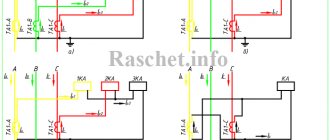
Checking the polarity of the winding terminals.
To carry out tests, connect an ammeter or voltmeter of the magnetoelectric type to the secondary winding with a certain polarity at its terminals.
Determination of the polarity of the terminals of the current transformer windings.
It is recommended to use a device with a zero in the middle of the scale, however, it can also be used with a zero located at the beginning of the scale.
All other secondary windings of the transformer must be bypassed for safety reasons.
A DC source must be connected to the primary winding of the CT, then a resistor must be connected in series to it to limit the discharge current. It is enough to use an ordinary power supply (battery) with an incandescent light bulb. Instead of a switch, you can simply touch the wire from the light bulb to the terminal of the primary winding of the CT and then remove it.
If the polarity matches, the arrow will move to the right and return back. If the device is connected with reverse polarity, the arrow will move to the left.
When the power is turned off for unipolar windings, the arrow moves with a push to the left, and otherwise, with a push to the right.
In the same way, you should check the polarity of the connections of other windings of the transformer.
Removing the magnetization characteristics.
The dependence of the voltage at the terminals of the secondary windings on the magnetizing current flowing through them is called the current-voltage characteristic, abbreviated as VAC. It indicates the correct operation of the winding and magnetic circuit and allows you to evaluate their serviceability.
In order to exclude the influence of interference from nearby power equipment, the current-voltage characteristic should be measured by first opening the circuit of the primary winding.
To construct the current-voltage characteristic, it is necessary to pass alternating current of various magnitudes through the CT winding and measure the voltage at the winding input. Such tests can be carried out by any laboratory bench with a power supply having an output power that allows loading the winding until the transformer magnetic circuit is saturated, at which point the saturation curve turns to a horizontal position.
The data obtained from the measurements must be entered into the protocol table. Using the tabular data, current-voltage characteristic curves are constructed.
Before starting measurements and after they are completed, it is imperative to demagnetize the magnetic circuit by several gradual increases in the current in the winding and subsequent reduction of the current to zero.
Important
To measure the values of currents and voltages, you should use devices of electromagnetic or electrodynamic systems that can perceive the effective values of current and voltage.
The presence of short-circuited turns in the winding reduces the output voltage in the winding and reduces the slope of the current-voltage characteristic. In this regard, when using a working CT for the first time, it is necessary to take measurements and construct a graph of the current-voltage characteristic, and during subsequent checks of the CT, after a time specified by the standards, the state of the output parameters should be monitored.
Equipment and circuit for checking the current-voltage characteristics of current transformers
A laboratory autotransformer (LATR), or devices containing it in its composition, is used as an adjustable voltage source to measure the current-voltage characteristics. The voltage must be absolutely sinusoidal, so thyristor power supplies are not suitable for testing.
To record the values of currents and voltages, you will need a laboratory ammeter and voltmeter .
When using devices built into the power supply, it is important to note that the ammeter must measure the rms value, and the voltmeter must measure the rms value.
The order in which devices are connected to the measuring circuit is also important. The ammeter should only measure the current directly in the winding being tested. The voltmeter is connected before it; the current through the winding of the device should not be taken into account, so as not to introduce additional error into the measurements.
The most accurate measurement option is to connect the measuring complex directly to the terminals of the current transformer.
But, if this is not possible, the option of using special current terminals on the panels of the cell with the current transformer being tested is allowed.
Measurement from terminal blocks located at a considerable distance and connected to the measurement object by control cables is unacceptable. In this case, the resistance of the cable line cores is added to the winding resistance, which is comparable in value.
It is not possible to test a current transformer for voltages up to 1000 V using LATR alone.
At too low voltages, the horizontal portion of the characteristic begins, so saturation will occur even with a slight turn of the LATR handle.
Therefore, a 220/36 V isolation transformer or any other can be connected between the source of regulated voltage and the winding being tested. At the same time, the control limit expands.
For safety reasons, the circuit connecting the LATR to the supply voltage network must have a protective device - a circuit breaker. It is also possible to create a visible gap when switching between transformers or their windings. A plug that plugs into an extension cord socket, the position of which can be seen from the boundaries of the workplace, is enough.
See below for an interesting video about taking the current-voltage characteristics from a CT using retom-21:
Volt-ampere characteristic of the current transformer how to remove it
Devices for proportionally converting alternating current to values that are safe for its measurements are called current transformers.
Such transformers are widely used in the field of electrical supply and power engineering and are manufactured in various designs, from small models placed directly on electronic boards to impressive-sized structures installed on special building structures.
The CT is checked to determine its performance, without assessing the metrological characteristics that determine the accuracy class and phase shift between the primary and secondary current vector.
How can you find out the calibration interval?
The value of the verification interval is determined by the design features of the device and is assigned by the manufacturer of this equipment. This period ranges from 4 to 16 years, depending on the model. You can find out this information in the following ways:
The passport contains the basic data for the equipment, including the calibration interval. But if the original passport documentation is lost, you can send an official request to the manufacturer, indicating the product model.
An alternative method involves studying state regulatory documentation. Also, the date of the next verification must be indicated in the previous certificate.