To order, you must fill out a questionnaire indicating the installation object
Electromagnetic anti-resonance single-phase voltage transformer type NAMI-110 UHL1 is intended for installation in electrical networks of three-phase alternating current with a frequency of 50 Hz with a solidly grounded neutral for the purpose of transmitting a signal of measuring information to measuring instruments, automation, protection, alarm and control devices.
Voltage transformers NAMI-110 TU 3414-023-11703970-03.
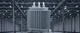
The voltage transformer NAMI-110 UHL1 has a single-stage non-cascade design. It consists of an active part placed in a metal housing. At the top of the housing there is an insulating cover with a metal pressure compensator, which compensates for temperature changes in the oil volume and protects the internal insulation from moisture. The compensator is closed with a protective cap with a slot for visual monitoring of the oil level. The transformer is filled with transformer oil of the GK brand.
Decoding of TRDN and fundamental differences
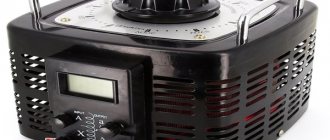
TRDN is a three-phase split-winding power transformer with natural oil cooling and forced air circulation. Such models are accompanied by a load adjustment mechanism, the change is ±8 x 1.5%. The transformer is used to convert high voltage electricity to low voltage distribution.
The main difference is the presence of three windings, which make it possible to obtain voltages of 35 and 10 kV. The tank is made of an oval shape; radiators are used to improve cooling. There is a special hook for installation on the upper frame. Air circulation is started by a 0.25 kilowatt engine, which is located below the radiator. Production is regulated by state standards 11677-85 and 11920-85.
Diagram of electrical equipment and primary connections, its structure
Let's figure out what the transformer consists of, as well as what primary connections are present:
According to the standard, the technique consists of several elements:
- Input of high, medium, low voltage. They are placed on porcelain insulation, the height of which depends on the voltage class.
- The electric current in this model passes through a 110 kilovolt current transformer. The product is used for differential protection.
- Inside there are 3 windings, high, medium and low voltage, which are placed on the magnetic core. The active part is immersed in special transformer oil. Monitoring and selection is carried out in the expansion tank.
- A separate block houses the on-load tap-changer, which serves as an element for regulating voltage under load. The latter has 16 positions.
- Nearby there is a cabinet with a motor drive, as well as redundant protection.
If we consider the primary circuit of a substation with a 110 kV transformer, then in the standard version there is a short-circuiter and separator with a linear disconnector RLND-110 kV or an SF6 circuit breaker on the high side, an oil circuit breaker on the 35 kV side, and a vacuum/oil circuit breaker on the 10 kV side.
On the bus bridge there will be a tap to the auxiliary transformer. For electrical equipment of this type, a ZON is installed, which is used according to network modes or during operational switching for repairs.
What are they made from?
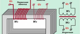
The voltage transformer consists of two coils. They will join the core made of their high-quality iron. Current is supplied through the first winding, resulting in a magnetic field. The phenomenon of magnetic inductance occurs. Please note that the magnetic field increases, but the flow can change its direction (both downward and upward). The field indicators are determined by the number of turns of the initial coil. The fewer of them there are, the lower the current readings should be expected.
If we consider the general diagram of a voltage transformer, it looks like this:
- primary and secondary findings;
- expander;
- terminal box and lifting bolt;
- oil level indicators.
The electrical diagram indicates the location of structural parts.
In particular, such basic elements as the primary and secondary winding sections, equalizing parts and magnetic wires are separately designated.
Auxiliary transformer (MV)
An auxiliary transformer is a power equipment that serves to provide the substation with an operational current of 110 V. A device of this type is installed by descending from a 10 kilovolt bus bridge. Power equipment is used by an indicator of operation of automation and protection.
To reduce losses, TM-63 models are installed at substations, and in rare cases TM-160. Read the device of TM and TMG in this article.
The purpose of TSN requires constant operation of the equipment. Therefore, an automatic transfer system (ATS) is also connected, which allows you to transfer power from one substation to another. Traction batteries are used as a backup element.
Completeness
Package Included:
1. Current transformers TNDM-110 (serial numbers 5938-А, 5938-В, 5939-С, 3760-А, 3760-В, 3760-С, 3755-А, 3755-В, 3755-С, 4083-А, 4083-B, 4083-C, 4318-A, 4318-B, 4318-C, 4936-
A, 4936-B, 4936-C, 4871-A, 4871-B, 4871-C, 4872-C, 4872-B, 4872-A, 5194-C, 5194-B, 5194-A, 4870-A, 4870-В, 4870-С, 141, 142, 143, 5015А, 5015В, 5015С, 5770-А, 5770-В, 5770-С, 22861, 22670, 5802-А, 5802-В, 5802-С, 5803- A, 5803-B, 5803-C, 111, 112, 113, 121, 122, 123, 5801-A, 5801-B, 5801-C, 6072, 6072, 6072, 3159 A, 3159 B, 3159 C, 6368 A, 6368 B, 6368 C, 3030 A, 3030
B, 3030 С, 4032 А, 4032 В, 4032 С, 3967-А, 3967-В, 3967-С, 4580-С, 4580-В, 4580-А, 4874-А, 4874-В, 4874-С, 5282-А, 5282-В, 5282-С, 5197-А, 5197-В, 5197-С, 5403-А, 5403-В, 5403-С, 5407-А, 5407-В, 5407-С, 5613- A, 5613-B, 5613-C, 4624A, 4624 B, 4624 C, 1270, 1213, 1091, 7305, 4855, 9020, 131, 132, 133, 539-A, 539-B, 539-C, 5563- A, 5563-B, 5563-C, 2986, 2986, 2986, 4053-A, 4053-B, 4053-C, 5152-A, 5152-B, 5152-C, 5210-A, 5210-B, 5210- C, 4066-A, 4066-B, 4066-C, 4065-A, 4065-B, 4065-C) - 131 pcs.;
Sheet No. 5 Total sheets 5
2. Current transformers TND-110 (serial numbers 1465-A, 1465-B, 1465-C, 3447-A, 3447-B, 3447-C) - 6 pcs.;
3. Passport for current transformers TNDM-110 - 131 copies;
3. Passport for current transformers TND-110 - 6 copies;
Current transformers 110 kV
On the 110 kilovolt side there is a current transformer for each phase, which performs a protective and, in rare cases, measuring function. The device is placed directly on the TRDN tank on porcelain insulation. Among the features stand out:
- The 110 kV current transformer is made of explosion-proof materials, which ensures the fulfillment of the assigned tasks.
- The product model is distinguished by reliable seals that create a tight seal, including at low temperatures.
- High-strength steel is used to produce the coating, which is complemented by hot-dip galvanizing. This also applies to components.
The equipment does not require maintenance. Periodic insulation monitoring is required. The product comes with a frame, including support posts.
Why is it worth buying a transformer from us?
When planning to buy a power transformer from ENERGOPROM-ALLIANCE, each client can count on individual service and qualified assistance from our specialists. All equipment is supplied with a manufacturer’s warranty, in a short time and at attractive prices.
Ordering transformers from our company is an opportunity to provide an industrial or residential facility with a reliable power supply system. In addition to supplies, we provide after-sales and warranty service, perform installation and commissioning of equipment. The company is the exclusive distributor of equipment produced by the transformer plant, offering customers reliable and productive equipment to Moscow companies.
Separator, short circuiter, EV, BB
We figured out why we need an auxiliary transformer and a 110 kV transformer. It remains to work out the issue with switching devices. We will talk about this equipment in detail in other articles. Let's look at the operating principle here:
- A short circuit is an electrical equipment that serves to create an artificial short circuit. This briefly disconnects the line before automatic reclosure (AR) is triggered. At the moment of a dead pause, the separator, which is a switching device, is switched off.
- In modern substations, 110 kilovolt SF6 or vacuum circuit breakers are more often used. This reduces the risk of shutdown due to failure of the automatic reclosure, speeds up the process, and protects the work of operating personnel.
Old equipment that was installed during the Soviet era is often used. But this practice is gradually moving away and modern switching devices are being installed.
Protections and automation
A power transformer is expensive and complex equipment, therefore, to reduce the risk of breakdown and the negative impact of a short circuit on the product, various types of protection are used. This issue will also be discussed in detail in future articles. The high voltage transformer protects:
- Gas protection. Triggers when there is intense gas movement in the tank, when the temperature rises or when it swings. Typically, gas protection in such models is provided for the on-load tap-changer and the active part separately. The jet relay is triggered immediately to turn off, the gas relay to the signal, then to turn off.
- Defensive protection. This is another type of protection that is used to turn off equipment when an interturn short circuit or overlap occurs on a bus bridge. To do this, the balance of currents is reduced, which is taken from CTs of 110 and 10 kV. This is the trigger zone, so TSN also falls here.
Another protective relay is considered to be backup protection like PUMA or similar. Serves as the last “stronghold”.
Output for repair
The power transformer TRDN 110/35/10 kV is taken out for repair using operational switching forms. The latter are developed based on the primary connection diagram and the switching devices used. To carry out this task you will need:
- To remove it for repair, the load on the 10 and 35 kilovolt side is removed.
- Disconnection of the 110 kV side is carried out through a short circuit-isolator connection or using SF6 circuit breakers.
- The output of overlays and automation is carried out on the basis of a relay circuit. The TSN load is transferred. According to the mode, ZON-110 kV is turned on.
Grounding is carried out on each side from which voltage can be supplied. The grounding blades on the switch or on the transformer disconnector RLNDz-110 are turned on, the circuit breaker on the 35 kV MV is turned on, and portable grounding is installed on the 10 kV bus bridge.
Lecture 13. Current transformers for voltages 110, 220 kV TFM series
Current transformers for voltages 110, 220 kV TFM series. Single-phase oil current transformers of the TFM series for outdoor installation are designed to power electrical measuring instruments and protective devices in AC power networks of 35 and 110 kV, for use in protection systems for electrical equipment of voltage classes up to 500 kV and higher.
The appearance of the TFM series current transformer is shown in Figure 3.15.
For measuring circuits, transformers are available in versions with accuracy classes 0.2 and 0.5. Transformers are available for temperate, cold and tropical climates.
The main parameters of transformers of the TFM series are given in Table 3.19.
Table 3.19. Main parameters of TFM series transformers
| Type | Rated voltage, kV | Rated primary current, A | Number of secondary windings | Rated secondary current, A | Rated secondary load with cos j = 0.8, VA in accuracy classes |
| 0,2 | 0,5 | 5P | 10R | ||
| TFM-110-II-U1 | 100; 200; 300; 400; 600; 1200 | 1; 5 | — | ||
| 750; 1500 | |||||
| 500; 1000; 2000 | |||||
| TFM-110-II-1-U1 | 100; 200; 300; 400; 600; 1200 | — | |||
| 750; 1500 | |||||
| TFM-110-II-2U1 (ХЛ1, Tl) | 2 x (300; 400; 500; 600) 2 x (750; 1000) | up to 5 | 1; 5 | ||
| TFM-110-II-ZU1 (ХЛ1, Tl) | 4 x (300; 400; 500) 3000; 4000 | up to 5 | 1; 5 | ||
| TFM-220-II-1U1 (ХЛ1, Tl) | 2 x (300; 400; 500; 600; 750; 1000) | up to 5 | 1; 5 | ||
| TFM-220-II-2U1 (HL1, Tl) | 4 x (300; 400; 500) 3000; 4000 | up to 5 | 1; 5 |
Transformers contain a primary high-voltage winding of one or several turns with a straight part passing through three, four or five ring magnetic cores with secondary windings and rigid cylinders insulating it, fixed in supporting insulating plates. The active part is installed on a metal base inside a porcelain cover filled with transformer oil and closed on top with an oil conservator.
The ends of the primary winding are connected to removable inputs mounted on the expander. Grounding terminals, low-voltage terminals of one measuring winding and two or three windings for protective circuits are located on the base of the transformer.
OJSC "Uralelektrotyazhmash" (Energomash) has been producing SF6 current transformers for outdoor installation with a rated voltage of 110 kV since 2003.
Current transformer for voltage 110 kV TRG series. The current transformer is designed to transmit measurement information signal to measuring instruments and protection and control devices in alternating current installations.
The transformer is intended for outdoor operation in areas with a temperate or cold climate, a non-explosive environment that does not contain aggressive gases and vapors in concentrations that destroy metals and insulation.
The main insulating medium of the current transformer TRG-110 II* is sulfur hexafluoride SF6 (SF6 gas) or a mixture of SF6 gas with tetrafluoromethane CF4 (freon-14). The use of a mixture of SF6 gas and tetrafluoromethane as the main insulation allows the current transformer to be used in areas with cold climates at ambient temperatures down to minus 55°C.
It is planned to produce current transformers for areas with cold climates using SF6 gas without a mixture of freon-14.
The gas environment is monitored using a density indicator.
Overall, installation and connection dimensions are shown in Figure 3.16.
When ordering, it is possible to supply it in climatic version T1 (upper operating air temperature plus 55°C).
Main features and benefits:
· The use of SF6 + CF4 gas or a mixture of SF6 + CF4 (depending on the climatic version) as the main insulation makes the current transformer practically maintenance-free during operation;
· Fire and explosion safety;
· Long service life - 40 years;
· Three transformation ratios in the ratio 1: 2: 4, switching of which is carried out by rearranging jumpers;
· High accuracy classes of the secondary winding for measurement, up to 0.2 S with sufficiently large secondary loads;
· The presence of a tap in the measuring winding of half the number of turns.
The main parameters of transformers of the TRG series are given in Table 3.20.
Table 3.20. Main parameters of TRG series transformers
| Parameter name | Meaning |
| Rated voltage, kV | |
| Highest operating voltage, kV | |
| Rated primary currents of the transformer, A | 200-400-800 300-600-1200 400-800-1600 500-1000-2000 |
| Rated secondary current, A | |
| Short circuit current parameters: | |
| Highest peak, kA | 102* |
| One-second thermal current, kA | 40* |
| Transformer service life, years | |
| Number of secondary windings: - for measurements - for protection | |
| Rated accuracy class of secondary windings: - for measurements - for protection | 0.2(0.5) 5P |
| Rated secondary load of secondary windings, V*A: - for measurements - for protection | 15, 30, 60 |
| Nominal limiting factor |
The current transformer of the TRG series is a structure in the upper part of which there is a metal casing mounted on a support insulator. The insulator, in turn, is fixed to the base, which contains the terminal box of the secondary windings. The primary winding and its terminals are fixed to the metal housing, and the secondary windings are located inside the housing. The internal cavity of the housing and insulator is filled with insulating gas.
The design of the primary winding allows you to obtain different transformation ratios when changing the number of turns by connecting sections of the primary winding in series-parallel.
The secondary windings are placed in electrostatic screens that equalize the internal electric field.
The active part of the magnetic circuit of the secondary winding for measurement is made of a nanocrystalline iron-based alloy, the windings for protection are made of cold-rolled anisotropic electrical steel.
The state of the gas environment is monitored using a density indicator with temperature compensation. The density detector is equipped with two pairs of contacts, which allows you to receive a signal at two values of gas density (pressure) and remotely monitor the state of the gas environment of the device.
The use of high-quality seals ensures leakage of no more than 0.5% per year (of the total mass of gas).
At the top of the current transformer there is a protective device that connects the internal gas volume to the atmosphere when the internal pressure is significantly exceeded (for example, when there is excess gas filling or internal arc flashover), which makes the device explosion-proof.
The transformer has no internal solid insulation, which reduces the level of partial discharges to a minimum and increases its reliability.
OJSC Ramensky Electrotechnical. In the past, the Ramensky branch of the Moscow production association "Electrozavod" named after V.V. Kuibyshev, and now Ramensky Electrotechnical OJSC, was created on the basis of the Metalist artel. The artel then employed only about 100 people and they produced toys.
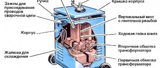
The year 1937 was a turning point in many ways; new product names appeared in the artel’s production tasks: electric arc welding transformers, low-voltage transformers for local mine lighting, spot welding transformers. Along with the change in the nature of the products produced, the name of the artel also changes. Metalist was renamed Ramensky Electromechanical Plant.
The main activities of the enterprise at present are:
· Production of anti-resonance voltage transformers from 6 to 330 kV (in the future up to 500 kV) of the NAMI series, resistant to ferroresonance and single-phase network faults to ground through an intermittent arc;
· High-frequency barriers such as VZ-630-0.5, VZ-1250-0.5, VZ-2000-1.0.
· High-voltage single-phase oil rectifier converters of the OPMD-100 ... 1600 series.
· Lightweight current transformers type TBMO-110 for automatic commercial metering of electricity for networks with a voltage of 110 kV (in the future - up to 500 kV);
· Reactors of the RUOM series for automatic compensation of capacitive currents at the site of a single-phase electrical network fault to ground with a power from 190 to 1520 kVA.
· The plant's products undergo mandatory certification by the State Standard of Russia, certification by the interdepartmental commission of RAO UES of Russia with the involvement of leading specialists in the field of electrical engineering. The enterprise is certified by the Russian Maritime Register of Shipping according to the ISO 9001-2000 system.
Voltage transformers (anti-resonant single-phase) for voltages 110, 220 kV NAMI series. Electromagnetic anti-resonance single-phase voltage transformer type NAMI is designed for installation in electrical networks of three-phase alternating current with a frequency of 50 Hz with a solidly grounded neutral for the purpose of transmitting a signal of measuring information to measuring instruments, automation devices, protection, alarm and control devices.
The voltage transformer NAMI-110 UHL1 has a single-stage non-cascade design (see Fig. 3.17).
It consists of an active part placed in a metal case. At the top of the housing there is an insulating cover with a metal oil conservator and an oil seal with a capacity of 1 liter, which protects the internal insulation of the transformer from moisture. The transformer and oil seal are filled with transformer oil of the GK brand. The oil seal communicates with the atmosphere through a breathing plug. There is a hole for adding oil to the main tank, plugged with a stainless steel ball and tightly sealed with a plug to prevent moisture from getting inside the transformer.
The main parameters of transformers of the NAMI series are given in Table 3.21.
Table 3.21. Main parameters of NAMI series transformers
| Type | Rated voltage of windings, kV | Rated VA power in accuracy classes* | ||||
| primary | secondary main No. 1 | secondary additional No. 2 | secondary main No. 3 | secondary main No. 1 | secondary additional No. 2 | secondary main No. 3 |
| 0,2 | 0,5 | 0,2 | 0,5 | |||
| NAMI-110 UHL1 | 110/√3 | 0,1/√3 | 0,1 | 0,1/√3 | ||
| NAMI-220 UHL1 | 220/√3 | 0,1/√3 | 0,1 | 0,1/√3 |
The voltage transformer NAMI-220 UHL1 has a cascade design and consists of two stages in porcelain housings with metal flanges (see Fig. 3.17).
Each transformer stage has two magnetic cores mounted on the corresponding flanges. Each transformer stage has a 2L oil seal that protects the internal insulation from moisture. The transformer and oil seal are filled with transformer oil of the GK brand. The oil seal of each stage communicates with the atmosphere through a breathing plug. There is a hole for adding oil to the main tank of each stage, plugged with a stainless steel ball and tightly sealed with a plug to prevent moisture from getting inside the transformer.
Current transformers for voltages 110, 220 kV TBMO series . Transformers are large-scale current converters and are designed to power electrical measuring instruments and relay protection in AC electrical networks of 50 Hz frequency with a solidly grounded neutral. The transformer is designed for outdoor operation in areas with temperate and cold climates.
The main parameters of transformers of the TBMO series are given in Table 3.22.
Table 3.22. Main parameters of TBMO series transformers
| Type | Rated voltage, kV | Maximum operating primary current, A | Rated secondary current, A | One-second thermal current, kA | Electrodynamic resistance current, kA | Number of secondary windings | Operating range of load change, VA | Nominal maximum factor of windings for protection No. 3, 4, 5, not less |
| Winding No. 1 - accuracy class 0.2S at cos φ = 1.0 | Winding No. 2 - accuracy class 0.5S at cos φ = 0.8 | Winding No. 3, 4, 5 - accuracy class 5P at cos φ = 0.8 | ||||||
| TBMO-110 | 1 and 5 | 0,5 — 2,0 | 5 — 20 | 7,5 — 30 | ||||
| TBMO-220 | 1 and 5 | 0,5 — 2,0 | 5 — 20 | 12,5 — 50 |
The transformer has a single-stage non-cascade design (see Fig. 3.18.). It consists of an active part placed in a metal case with transformer oil of the GK brand. At the top of the housing there is an insulating cover with a metal oil conservator and an oil seal that protects the internal insulation from moisture.
OJSC "Zaporozhye Plant of High-Voltage Equipment" is one of the largest electrical engineering enterprises in Ukraine and well-known in many countries of the world. For 50 years, the company has been developing, manufacturing and supplying electrical equipment to almost all regions of the world. Our equipment ensures the transmission and distribution of energy at the largest energy facilities in the CIS countries and in 38 countries abroad.
The production and testing base of the enterprise allows us to ensure the manufacture of products according to progressive technological processes and on modern technological equipment with the necessary quality control, to test products in full, provided for by national and international standards and special requirements of the Customer. The quality system is certified by TNO CERTIFICATION according to the international system ISO-9001, certificate registration number S97.272.
The company produces a significant volume of electrical products:
· measuring current transformers for connection to a network with voltages from 10 kV to 1150 kV, rated primary current from 15 A to 4000 A;
· measuring voltage transformers and voltage dividers for inclusion in a network from 35 kV to 1,150 kV;
· complete switchgears for voltages of 6.10 and 35 kV, rated currents from 630 A to 3150 A, with low-oil, vacuum or SF6 circuit breakers;
· complete transformer substations for voltage 6-10/0.4 kV with power transformers 160-400 kVA;
· prefabricated one-way service chambers for voltage 6-10 kV, rated currents from 400 A to 1000 A with low-oil or vacuum circuit breakers;
· disconnectors for voltages from 10 kV to 330 kV, rated currents from 400 A to 3150 A (indoor and outdoor installation);
· reconstruction and improvement of the technical level of the switchgear substation by replacing oil circuit breakers with vacuum or SF6 circuit breakers with the installation of modern relay protection and automation circuits.
The advantage of the supplied equipment is:
· quick and easy installation;
· small installation area;
Convenient and safe service;
· reliability in operation;
· low operating costs.
At the request of the Customer, the company provides a full range of services for installation and commissioning of the supplied equipment with subsequent service during the warranty period.
Measuring current transformers of voltage class 110, 220 kV. Measuring current transformers are manufactured with SF6 gas (TOG series) or oil filling, with porcelain or silicone external insulation.
The main parameters of current transformers produced by JSC Zaporozhye High-Voltage Equipment Plant are given in Table 3.23.
Table 3.23. Main parameters of current transformers produced by OJSC "Zaporozhye High-Voltage Equipment Plant"
| Product type | Rated primary current, A | Rated secondary current, A | Number of secondary windings | Thermal resistance current, kA | Electrodynamic resistance current, kA | Rated secondary winding accuracy class | Rated maximum factor of secondary windings for protection |
| TFZM220B-SHU1, TFZM220B-SHHL1 | 300-600-1200 | 1 or 5 | 9.8-19.6—39.2 | 25-50—100 | 0.5 | 15″ 10* | |
| TFZM220B-1UU1, TFZM220B-1UHL1 | 500-1000-2000 | 1 or 5 | 9.8-19.6—39.2 | 25-50—100 | 0.5 | 25** 20* | |
| TFZM220B-GP, TFZM220B-IT1 | 300-600; 400-800; 600-1200; 750-1500 | 1 or 5 | 10-20; 9-18; 20-40; 17-34; | 27-54; 24-48; 54-108; 45-90 | 0.5, | 16** 12* | |
| TFZM 110B-1U1, TFZM 110B-1HL1 | 50-100; 75-150; 100-200; 150-300; 200-400; 300-600; 400-800 | 2-28 | 10-126 | 0.5 | |||
| TFZM 110B-SHU1, TFZM 110B-SHHL1 | 750-1500; 1000-2000 | 1 or 5 | 0.5 | ||||
| TFZM 110B-IVU1, TFZM 110B-IVХЛ1 | 100; 150; 200; 300; 400; 600; 750; 1000; 1500; 2000 | 1 or 5 | 0.5 | ||||
| TOM 220B-1U1, HL1, T1, | 600; 800; 1500; 2000; 3000 | 1 or 5 | 22.8+63 | 41.4+120 | 0.2; 0.5 | ||
| TOG110-II-1U1 | 50; 75; 100; 150; 100-200; 150-300; 200-400; 300-600; 400-800; 500-1000;750-1500; 1000-2000; 1500-3000 | 1 or 5 | 0.2; 0.5 « | 20 or 30 | |||
| TOG220-II-1U1*" | 300-600; 400-800; 500-1000; 600-1200; 1000-2000; 1500-3000 | 1 or 5 | 0.2; 0.5 |
The appearance of current transformers produced by JSC Zaporozhye High-Voltage Equipment Plant is shown in Figure 3.19.
Voltage transformers of class 110, 220 kV. Voltage transformers are manufactured with SF6 or oil filling, with porcelain or silicone external insulation.
The main parameters of voltage transformers produced by JSC Zaporozhye High-Voltage Equipment Plant are given in Table 3.24.
Table 3.24. Main parameters of voltage transformers produced by OJSC "Zaporozhye High-Voltage Equipment Plant"
| Product type | Rated voltage, V | Rated power in accuracy class, VA | |
| primary | secondary main winding | secondary additional winding | |
| 0.2; 0.5; 1.0; 3.0 | |||
| ZNOG-M-220-1UHL4 ZNOG-M-220-1TS4*, | 220000:Ö3 | 100:ÖZ | 150;400;-;- |
| ZNOG-M-220-NUHL4, ZNOG-M-220-ITS4* | -;-;600; 1200 | ||
| ZNOG-M-110-1UHL4, ZNOG-M-110-1TS4*, | 110000:Ö3 | 100:ÖZ | 150;400;-;- |
| ZNOG-M-110-NUHL4, ZNOG-M-110-ITS4* | -;-;600; 1200 | ||
| NKF-110-II-U1, | 110000:Ö3 | 100:ÖZ | 100; 200; 400; 1000 |
| NKF-110-II-T1, | -; 400; 600; 1200 | ||
| NKF-110-III-U1, NKF-110-III-T1, | -; 400; 600; 1200 | ||
| NKF-110-II-U1-I** | 100:3 | -; 400; 600; 1200 | |
| NKF-220-II-U1, NKF-220-II-T1, | 220000:Ö3 | 100:ÖZ | 100; 200; 400; 1000 |
| -; 400; 600; 1200 | |||
| NKF-220-III-U1, NKF-220-III-T1 | 100; 200; 400; 1000 | ||
| -; 400; 600; 1200 | |||
| ETN-220 | 220000:Ö3 | 100:ÖZ | 200; -; -; 800 |
The appearance of voltage transformers produced by JSC Zaporozhye High-Voltage Equipment Plant is shown in Figure 3.20.