The appearance of wires with an integrated load-bearing part has made it possible to increase the resistance of overhead power lines to external influences. When installing a SIP cable from a pole to a house, it is necessary to use anchors that securely hold the main line. If installed correctly, the wiring will last at least 25 years. Violations of technology lead to power failures or fires.
What is SIP cable
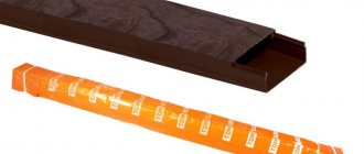
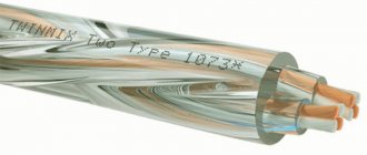
Self-supporting insulated wire is intended for organizing overhead power lines or creating lighting networks. Depending on the cross-section and insulator, the cable is designed for voltages from 600 V to 35 kV. The product was developed in the 60s. last century in Finland as an alternative to classic lines suspended on a steel cable.
The insulator is made of cross-linked polyethylene, resistant to temperature changes and ultraviolet light (the neutral or supporting core may not be equipped with a protective coating).
Varieties and differences
In accordance with the GOST 31946-2012 standard, several types of cables are produced in Russia (all equipped with aluminum conductors):
- SIP-1, designed for voltages up to 380 V and without an insulator on the supporting core;
- SIP-2, used in lines with voltages up to 380 V and equipped with a protective layer on the supporting core;
- SIP-3, designed for up to 20 or 32 kV (depending on the thickness of the insulator - 2.3 and 3.5 mm, respectively);
- SIP-4, which does not have a zero load-bearing core and consists of 2 or 4 cores (there are modifications with additional wires for organizing lighting);
- SIP-5, which differs from SIP-4 insulator made of light-stabilized polyethylene.
Reading Markings
The designation SIP stands for “self-supporting insulated wire”, the number indicates the type of cable. There are modifications with letters to mark special characteristics (for example, the letter “g” is used for a sealed cable model, and “n” is used for products with a flame retardant insulator). Standard insulation can withstand prolonged heating up to +90°C. There is a modification marked “t”, the protective layer is not destroyed at +120°C.
Both cable options are designed to heat up to +250°C during a short circuit.
Advantages and disadvantages
Main advantages of the carrier cable:
- the presence of insulation prevents short circuits when foreign objects fall (for example, broken tree branches);
- the supporting core increases the resistance of the line to breaks;
- the dimensions of the overhead line are reduced and the distance from the pole to the wall of the building is reduced;
- protection of the main line from theft of electricity is ensured by installing additional cables;
- long service life (at least 40 years);
- the smooth surface protects the highway from sticking wet snow;
- It is possible to carry out part of the installation work without turning off the voltage.
Product shortcomings noted by installation teams:
- the need to train personnel in working with cables of the SIP series;
- increased cost (compared to products with bare cores);
- risk of damage to the insulator due to prolonged contact with foreign objects;
- increased specific gravity due to the use of a load-bearing core and a thick insulator;
- flammability of the protective layer, limiting the use of products indoors.
Which one is suitable for connecting to the house?
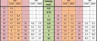
For connection to a residential building or cottage with a load power of up to 3–4 kW, a 2-core SIP-4 cable with a cross-section of 16 mm² is suitable. If the building has heating boilers or household appliances with high energy consumption, then a 4-core wire rated for 380 V should be used.
In both cases, it is necessary to organize a separate grounding circuit to protect people from electric shock due to insulation breakdown.
We monitor the quality of connections and even consumables: crappy tires and NShVI.
And the last part of the post about fires and so on is unexpected. It turns out that if we are dealing with introducing power into a house, then we also need to pay attention to the busbars, on which some unscrupulous electricians are trying to make an N/PE separation.
If you look at all sorts of “pole input panels” from developers or local electricians, they usually use the most common screw-type brass busbars on a DIN rail. But they have two jambs: clamping the wire with the end of the screw and the low current for which they are designed (usually up to 63A).
As we remember, hehe, aluminum has fluidity under screw pressure. Therefore, if you clamp the SIP directly into such a bus, then sooner or later you can get crap like this:
Cheap brass N/PE bus bar, burnt due to poor contact
And if you want to joke even more, then look at how drilled this brass block is. Maybe its cross-section itself will allow it to pass a current of 63A, but if you make holes in it, then the cross-section of the bar in these places will decrease.
What is the worst case scenario for an accident with zero burnout on the main line? If we have a TN-CS system, re-grounding the zero in the line is bad - then a huge equalizing current can flow through such a bus. In the worst case, the current is up to the rating of the inserts at the substation that protect this line.
Therefore, it is NOT necessary to use such busbars to enter a SIP or a PEN separation unit! Take distribution blocks. I use ABB BRU/DBL, but the same IEK and TDM make “RB” blocks, which also have the right to life and have reliable contact (and are inexpensive). You can take them for a current of 125A and not worry.
And the reader sent me the next batch of photos again. The input data is as follows: in the switchboard there is a C25 machine at the input, then an UZMka. One day it was discovered that one of the contacts of the machine had burned out, and the UZMka began to drain from the rack.
Poor quality of the NShVI tip: the UZMka melted
This is what a burnt contact on a machine looks like. It can be seen that the skirt of the NShVI tip melted and glass flowed along the wire.
Bad ka
quality of NShVI tip: UZMka melted
UZMka got it because of the thermal release of the machine: the temperature from the poor contact was transferred to the internal glands of the machine, which heated its body. And its body heated the UZMka, which stood nearby. So she floated.
Poor quality of the NShVI tip: the UZMka melted
When the heating became stronger, the machine began to turn off via the thermal release and only then the problem was noticed.
The author of the photos and I wondered why the NShVI melted and settled on two versions: either that the NShVI was made of some strange metal (its color resembles a Chinese one) and the bad contact was inside it, or that the bad contact was inside the machine.
Poor quality of the NShVI tip: the UZMka melted
Selection of fittings for installation
When selecting components, take into account the facade material:
- Construction nails or screws are used for fastening to a wooden surface or plaster. Screws provide increased strength, but holes must be drilled into the material before installation.
- For concrete or brick structures, take plastic dowels and insert them into pre-drilled holes. If there is decorative trim on the surface of the wall, then it is necessary to install an amplifier under it, rigidly attaching it to the base. Otherwise, with a gust of wind, the cable will tear off the clamps and part of the building’s cladding.
Calculation of power consumption
Is 15 kW enough? This question should concern owners. The maximum demand is calculated simply: the power of all household appliances (kettle, iron, mixer, microwave oven, hob, hair dryer, TVs and computers), boilers, water heating units, heated floors, lighting is summed up. To assess the real power requirement, experts recommend using a reduction factor of 0.7. The probability of turning on all electrical appliances at the same time is low. In this case, it makes no sense to overpay for an additional energy resource. As a rule, for premises with an area of 100 m2, 15 kW is enough. If you need more electricity for life support, you will have to fork out more. The trick of dividing the plot into parts will not work: the owner has the right to use the benefit once every three years.
Fasteners for SIP
To install a line of SIP series cables, use:
- anchor, support and intermediate clamps;
- brackets and mounting hooks;
- yokes and clamps for holding metal tape;
- insulated staples;
- spiral knits;
- die and mounting clamps;
- piercing and branch couplings;
- rollers and auxiliary fittings (for example, protective caps for cut cable lugs).
Clamps
To connect several cables into a single line, special clamps are used that are characterized by increased strength.
The design has an extended clasp that holds the line when branches fall. The clamps are made of plastic that does not lose strength when exposed to ultraviolet radiation or when the temperature drops to -50°C and below. Do not use standard cable ties, which will burst after 6–8 months of being outdoors.
Anchor clamps
To hold the SIP line on the wall, anchor clamps made of aluminum alloy and reinforced polyamide are used. The mounts are designed to withstand exposure to sunlight and low air temperatures. The clamps differ in maximum breaking load, cross-section and number of cores, and are suitable for organizing subscriber branches of power supply lines. The wedge clamp holds the cable and does not destroy the protective insulation.
Brackets
Brackets are used to hold wires on supports or walls. The use of existing structures (for example, mounting loops or reinforcement pins) is not permitted. The clamp is attached to the poles using a metal bandage tape clamped with a yoke. To make the clamp, stainless or galvanized steel is used, the edges of which undergo a machining cycle. The tape is characterized by increased elasticity and is supplied in coils with a length of 25 m. A special tool is required for installation and tightening with a yoke.
The fittings for fixing SIPs are made of glass fiber reinforced polyamide. Products vary in size, configuration and maximum load. The brackets can withstand cooling down to -60°C without loss of strength and are not destroyed under the influence of ultraviolet radiation. Fastening elements are designed for installation at sub-zero air temperatures.
There is reinforced fittings made of aluminum alloy using high pressure casting technology.
Attachment to different surfaces
If the cottage or residential building is located at a short distance from the power line, then it is necessary to lay a branch based on the SIP cable, and then supply power to the building. For installation work, you will need special fasteners, the range of which depends on the design and number of supports. Clamps are installed on poles and walls. SIP cable does not require cable tensioning or trench digging.
To the post
To fix the brackets on the supports, use a perforated tape made of galvanized steel and equipped with a clamping yoke. To connect insulated cable cores into bundles, special plastic clamps are used that can withstand up to 5 years of operation. Intermediate or anchor brackets are placed on the tape to hold the main line and the branch, respectively. Elastic metal allows you to fix lines on supports with a quadrant or round profile. The strength of the clamp depends on the correct tightening of the yoke.
Protective caps
With any branch, wire cuts appear, which must also be reliably sealed. To seal such terminations, protective caps are usually used.
The cap on the clamp can be built-in or removable. It is better to choose punctures with built-in ones. Since, being at a height, on a support it is not always convenient to take this cap out of a bag or pocket, and often it is completely lost.
Technical characteristics and nomenclature of insulating caps:
Ensto PK99, 553, 555
Niled CE 6.35, 25.95
KVT CI
IEK CI
If you do not use it, then the SIP will “suck” so much moisture over time that a small puddle may form in your accounting cabinet!
Here is a clear example of the lack of SIP sealing at the entrance to the house and its consequences:
Installation of SIP from pole to house
The procedure for connecting a residential building to the power supply line using SIP must be carried out by a professional team. Installation work requires the use of special tools and a lift on the vehicle chassis. To move equipment under power lines, a permit is required, and since the wiring remains live, the operator must use protective dielectric gloves and boots.
Armature
To install the cable you need:
- piercing clamps with a protective cap (the number of elements depends on the number of wiring strands);
- anchor clamps (for example, for a standard single-phase 220 V line, 2 clamps are required for each intermediate support and wall);
- metal tape (1–1.5 m of material is required for a post);
- yokes for fixing the tape (the number depends on the number of staples);
- aluminum or plastic brackets, which are attached to the facade of the building with anchors, and to the supports using steel tape;
- plastic clamps;
- fastenings for the facade of the house.
Installation of fasteners and cable routing
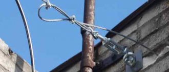
Since it is unacceptable to violate the integrity of the power line support, steel tapes are used to install the brackets. The clamps are arranged in 2 rows and tightened with yokes. The wedge is removed from the anchor clamp and pulled through the resulting cable channel. The spacer is then hammered back in and the clamp is mounted on the wire bracket on the bracket. To correct the sag, a dynamometer is used, since weak or excessive tension causes destruction of the insulation and conductors.
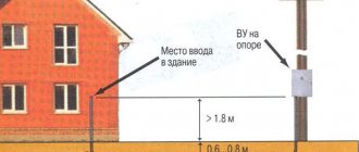
To create a branch, piercing clamps are used, allowing work to be carried out without turning off the power supply. The exposed ends of the wiring are covered with sealed caps, and the wires are tied together with clamps into bundles. If the clamp had to be removed during the work, reuse of the product is prohibited. The SIP branch is taken to the side of the house, the bracket is secured to the facade with screws or bolts. The line between the pole and the building must be located at a height of 2.75 m and have no sag. The distance from the support to the building is no more than 25 m.
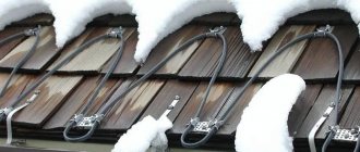
Façade layout
Since the shell of standard SIP wires supports combustion, the line is not laid out along the facade. It is allowed to fix SIPn series products equipped with non-combustible insulation on the walls. At the place where the power line is attached to the facade, copper conductors are connected to aluminum conductors using bimetallic sleeves. The cable can be brought into the building through a pipe made of plastic or metal.
The location of the channel should prevent precipitation or condensation from penetrating into the structure.
Wire extension
To lengthen SIPs, couplings with a metal sleeve that is deformed with pliers or a press are used. For cables with an integrated load-bearing conductor, joining in the span is allowed. For SIP-4, which does not have a power core, the connection is made only on a support. It is allowed to join the segments using a piercing clamp for phase conductors and a die with a screw for the carrier line (if available).
Grounding board and surge protector on the facade of the house. We solve all problems with one shield.
In general, this option is quite established in my mind and now I talk about it at all consultations on shields. And I myself liked this idea in the style of “Damn! How come I forgot about you?” To understand what I’m getting at, let’s write down the problems that we need to solve when introducing electricity into the house:
- Grounding and lightning protection circuit . It is the contour , and not the notorious triangle that everyone loves so much. If you are doing lightning protection, then you need to drive grounding conductors into at least two, or better yet, four corners of the house and tie it all into a single strip. If you don’t, then it’s enough to plug in one ground electrode with control of the circuit resistance.
- PE input from the ground loop into the shield . Most often, the ground loop itself is made of a steel strip or wire. It is clear that dragging her into the shield is stupid. How can I get it into a white and beautiful AT/U series shield, for example? You can also tell me to weld it to the shield body, heh. Therefore, somewhere on the street/basement, a bolt is welded to the strip, to which an ordinary PuV/PuGV copper wire with a cross-section of 10 square meters is screwed through a TML tip, which is then brought into the house. Such a connection must be somehow protected from earth, moisture and made serviceable.
- External disconnector in case of fire or emergency . It would be nice if there was a disconnect switch somewhere outside the house that could be used to turn off the house.
- SPDs . They need two things (in the toughest version): a metal shield, where they can safely and harmlessly bang or catch fire, and PE as close as possible to the ground loop. And between the SPDs and the shield that we protect with them (our shield at home), it is also advisable to make some distance (several meters of cable).
- Transition from SIP to copper . We have already talked about this: SIP cannot be brought into the house.
What are we doing? At first it seems that I wrote out a list of points that contradict each other. How the hell do you switch from SIP to copper and immediately install SPDs and also connect a strip from the circuit?
So here’s a good and competent (in my opinion) solution: a metal input panel on the facade of the house! This is not a shield for the meter (but it can be combined with it), but a special shield where SPDs can be installed, SIPs in a metal pipe and a steel strip from the ground loop can be installed.
It is most convenient to make such a shield based on the ST series from DKC. Here is the shield that I made for a set of shields in Pushkino:
Shield for main protection and surge protection devices on the facade of the house
Here we have the main ground bus (GZB), to which PE will come from the ground loop and a number of “Input-Output” terminals (terminals of 16 squares, connected in pairs by jumpers), which are needed to connect the input cable from the ground. , input cable to the house and make a branch for installation of SPDs inside this panel. The shield itself will be located on the wall of the house.
And here is another example of such panels (metering for a pole and surge protection for the facade) for a house in Gribanovo:
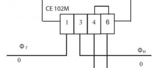
The metering panel consists of an input machine, a meter and a voltmeter
The beauty of this idea is that we are not trying to cram brutal and voluminous things into our beautiful DIN-rack system (as was the case, for example, in the panel in Tomilino), but are bringing everything voluminous to the facade of the house. And a three- or five-core cable will already arrive in the shield (cabinet) of the house, and in that shield it will be possible to operate in exactly the same way as in an apartment – just take the power and use it, without thinking about any grounding systems.
A small metering panel and an SPD panel for this panel (Gribanovo)
In the end, we can say this: if you know that you will never need any SPDs, lightning protection and other amenities, then switch from SIP to copper on the facade of the house and install it in the house right away. If you want to make a reserve for the future, then organize yourself such a shield on the wall (facade) of the house and drag the input from the ground loop and the input from the pole there. And in the future it will be possible to turn around in this shield.
It so happened that Kirich Funt was redoing another input from his relatives, but in a different house. And that’s where we made such a shield on the facade with a reserve for the future.
DKC ST series panel on the facade of a house for switching from SIP to copper, grounding, SPD and metering (Funt)
The air input is transferred using compresses to two cables VVG-ng-LS 1×10, which are then lowered in a pipe to the shield on the wall.
Transition from input to VVG cables (Funt)
The shield looks like this for now. If in the future you need to add SPDs or something else here, then there is a place.
DKC ST series panel on the facade of a house for switching from SIP to copper, grounding, SPD and metering (Funt)
Features of SIP laying
Cables of the SIP series are designed only for aerial installation in open space (in accordance with the requirements of GOST R 52373-2005). The line is laid along the supports, providing a safe gap between the wire and the ground, and then stretched to the facade of a residential or industrial facility. It is not allowed to lay SIP underground, in closed pipes or cable ducts, or indoors.
To the intermediate support
If the distance from the power line pole to the facade of the building is more than 25 m, then the installation of an intermediate support is necessary. A bracket is fixed to the risers with metal tapes, onto which a pair of anchor clamps are placed. The laid cable is pulled with a hand winch and secured with wedges, leaving a small loop between the fasteners. There are special hangers for intermediate supports, equipped with clamps to prevent the wiring from shifting under the influence of wind.
To the load-bearing wall of the building
The line is drawn to the facade and secured using an anchor clamp located on the bracket. The base is fixed to the partition using screws or dowels, placing relief washers under the screw heads. If the building is built using frame technology, then the bracket is placed on a power beam. For fastening, use cap screws (nails should not be used due to insufficient connection strength).
Underground input method
It is prohibited to lay SIP underground, since the wire is not additionally protected from mechanical loads, the aggressive effects of groundwater and chemicals. It is intended only for overhead installation of power lines.
If there is a need to connect such a wire to a garage or other consumer underground, this is done by preparing a trench and laying the wire, previously placed in a metal or plastic pipe. Entry into the house is carried out through a hole in the foundation, under it or through a wall, raising the wire along the facade to the entry point.
Safety precautions
Basic safety requirements when laying SIP cables:
- Do not carry out work in low light or high humidity (for example, during rain or fog).
- For installation, use serviceable tools and components that have certificates of compliance with standard requirements.
- Do not use components that have visible damage (for example, cracks or breaks in the insulation) or are not intended for the cable being used.
- Carry out installation in protective dielectric clothing. Equipment handles must protect the operator from electric shock. To insulate live lines, use special overlays. When performing work at height using lifting equipment, a work permit is required. In this case, installation can only be carried out by professional teams.
Possible benefits
At the legislative level, the rules for the technological commissioning of residential buildings have been approved. (Government Decree No. 861 of December 27, 2004). This means drawing a line to the border of the land plot.
The conditions under which the preferential tariff applies are stipulated:
- power limit 15kW;
- maximum distance to the object: within the city limits 300 meters, for settlements - 500;
- Energosbyt has the opportunity to connect a residential building to the general network (no one will pull a special power line).
If all conditions are met, the owner of the building pays 550 rubles. Within six months, energy retailers are required to connect the building to the general network.
If the terms of the tariff agreement are not met, an individual estimate is drawn up. In this case, the bill runs to tens of thousands of rubles. The current, as a rule, is supplied to a pole located near the wall of the structure. The owner draws up the home connection plan independently. Then he goes to apply for permits.
Installation errors
Common mistakes when installing SIP wires:
- Insufficient or excessive line tension, leading to increased load and premature failure of the load-bearing core or insulation. To ensure the required cable slack, use a dynamometer built into the hand winch.
- Repeated use of piercing clamps that does not allow the cable to be properly secured. SIP fasteners are disposable and must be disposed of if removed.
- Weak tightening of steel bands. Under the influence of temperature changes or wind, the brackets begin to slide along the surface of the pole. The defect can be easily eliminated by tightening the clamp with a special tool.
When laying wires, you should check the condition of the insulation: damage to the sheath leads to short circuits or electric shock to people. The cable is unwound on a surface without sharp objects. If tears are detected on the protective layer, the defective area is cut out. To join pieces of SIP, crimp sleeves are used, followed by insulation of the coupling. The use of artisanal connection methods (for example, twisting of cores) is strictly prohibited.
How to choose a machine?
Before you begin installing protective circuit breakers, you need to select them and also understand the intricacies of connection. People who want to know how to wire a circuit breaker ask various questions. For example, are the circuit breakers in the distribution board connected before or after the meter? Should an automatic input be installed? These and other connection nuances are of interest to users.
Basic parameters of circuit breakers
The characteristics of circuit breakers include:
- Rated current value (in Amperes).
- Operating voltage of the electrical network (in Volts).
- Maximum short circuit current.
- Ultimate switching capacity.
- Number of poles.
The maximum switching capacity is characterized by the maximum permissible value at which the switch is capable of operating. The PKS of household devices can be 4.5, 6 or 10 kA.
The cause of overload is the connection to the electrical network of devices with excessively high total power, which leads to exceeding the permissible temperature of contact connections and cables.
Taking this into account, it is necessary to install a packet in the circuit, the value of the shutdown current of which is not less than the calculated value, and better - if it slightly exceeds it. To determine the calculated current, you need to sum up the power of the devices that are supposed to be connected to the circuit (for each of them this indicator is available in the passport). The resulting number must be divided by 220 (the standard voltage value in a household network). The result obtained will be the value of the overload current. It should also be taken into account that it should not exceed the current rating that the wire can withstand.
The magnitude of the shutdown current during a short circuit is the indicator at which the circuit breaker is switched off. The short-circuit current is calculated when designing the line using formulas and reference tables, as well as using special equipment. Based on the obtained value, the type of protection is determined. At small sites and in household networks, type B or C machines are used.