The fact that in modern houses and apartments it is necessary to install protective shutdown devices has already been said more than once. Their main goal is to protect human life from the effects of electric current. But is it always possible to carry out installation, given that the network can be different - three-phase and single-phase, with and without a grounding protective conductor. Let's talk about how to connect an RCD without grounding. The scheme by which these devices are connected is not complicated. If you do all the apartment wiring yourself, you can easily handle installing an RCD. But the best decision would be to entrust this work to professionals.
Before talking about how to connect an RCD without grounding, you need to have a clear understanding of the types of electrical household networks.
Device connection sequence
When connecting, it is important to remember that both the phase component and the zero of the circuit on which the protection is installed must pass through the device.
RCDs are equipped with output and input contacts. Each terminal has its own marking, so it’s quite easy to figure out what goes where. Most often, we can find the input contacts on top, and the output contacts on the bottom.
All devices, both above and below, must fit tightly, otherwise heating cannot be avoided. Conventionally, all connection schemes are divided into two types: single-level and multi-level.
The first type is suitable for individual systems or protecting entire wiring at once. The device of the machine provides protection only from electric current in an apartment or house.
A common example: voltage protection when operating a washing machine in the bathroom.
Just do not forget that with such an RCD you also need to organize the correct connection of the circuit breaker, which will save the circuit from short-circuiting.
When you connect an RCD for all consumers, place the device next to the meter.
With multi-level protection, you will have to make precise calculations for each device that operates on the network.
In other words, the connection should be made in such a way that if one of the RCDs burns out, all other machines remain operational. This rule also applies to the main machine.
If it is turned on, then the RCDs both above and below should function without problems. It is believed that connecting such a complex system is best left to professionals.
The price may seem high to you, but this move will be much safer for the whole family and household appliances.
Do not forget that the most dangerous circuits are protected by separate RCDs. For sockets, the contacts must be routed to the input zero terminal using the shortest route.
Cascade connection of devices is also allowed if the upper RCDs are less sensitive than the terminal ones.
Video:
An important nuance: if your RCD has tripped and the electricity has turned off, you cannot simply turn on the devices again. First you need to find the problem, and only then make the connection.
Otherwise, some or even all of your appliances will burn out.
If after this the RCD turns on when starting up, then some separate device is to blame. If not, then the problem may be not only in the apartment, but in the entire entrance.
Errors when connecting an RCD occur quite often, and you can’t do it on your own - it’s better to call a competent technician.
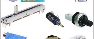
Marking
The marking is applied to the front panel of the device; we will tell you what it means using the example of a two-pole device.
RCD marking
Designations:
- A – Abbreviation or manufacturer’s logo.
- B – series designation.
- C – The value of the rated voltage.
- D – Rated current parameter.
- E – The value of the shutdown current.
- F – Graphic designation of the type of disconnecting current, can be duplicated with letters (in our case, a sinusoid is shown, which indicates the type of AC).
- G – Graphic designation of the device on circuit diagrams.
- N – Value of conditional short-circuit current.
- I – Device diagram.
- J – Minimum operating temperature (in our case: – 25°C).
We have provided standard markings that are used in most devices of this class.
Is it possible to connect an RCD without grounding?
The use of such a protective device almost always makes sense, even when the connection diagram is a simple two-wire with zero and phase. In order to more clearly understand the operating features of such a device, to find out all the details and the most interesting specific points, you need to understand this issue in as much detail as possible. Based on this, the most appropriate conclusions can be drawn.
By and large, you can consider the RCD as a kind of “calculator”. Its connection diagram, if grounding is not used, is very simple. The phase and neutral wires pass through the product. The load that comes to them is monitored as carefully as possible, after which a comparison is made.
If suddenly the wiring is damaged or a leak begins to appear in the consumer’s electrical network, then the current begins to flow through the damaged insulation. The magnitude of this current is usually very small. This could be, for example, tens and hundreds of milliamps. However, despite its insignificant parameters, it can be sufficient to cause significant damage to human health.
A residual current device is used to equalize the current that passes through the phase and neutral wires. If suddenly there is a deviation in current values, then the contacts open automatically, which interrupts the supply of electricity to the section of the network that was damaged. Now you can move from theory directly to practice, that is, to an everyday situation that is understandable to everyone.
For example, in a house there is a washing machine in the bathroom. The electrical wiring is of a two-wire type, that is, with a phase and a neutral, but there is no grounding. So far, no RCD has been installed. The phase wire and insulation may be damaged in the washing machine. After this, the wire may begin to touch the metal body of the device, causing it to be under a certain voltage.
If a person touches the body, he will become a conductor. Therefore, electric current will begin to flow through it. This process will continue until the person releases the metal body. But before that time, he will probably be shocked and beaten due to the effects of the current. Surely a person will also hope for protection that can disconnect the damaged area, but if there is no RCD, then there is no protection. Therefore, you should rely solely on your own willpower. Otherwise, a person may simply lose consciousness and fall.
If an RCD is installed, then if you touch a metal case that is energized, the device will instantly sense a current leak and turn on. Therefore, the damaged area will turn off almost immediately.
This is due to the fact that if the first signs of current “distortion” occur on the wires, both phase and neutral, the automation begins to work. She immediately leaves the washing machine simply without power. It is unlikely that a person will even have time to feel a slight tickling on the body. In this case, the person will probably be more puzzled by the characteristic click of the relay located in the hallway.
Moreover, the time during which a person will feel the current is so insignificant that he is unlikely to have the opportunity to even feel the effects of the electric current. Nowadays, you can easily find a special video online that shows testing of a modern RCD. There, a person intentionally grabs a bare wire connected directly to the residual current device. After touching the wire, the RCD turns on almost instantly. Because of this, the person did not even feel any discomfort or unpleasant sensations.
It is unlikely that anyone will not notice the benefits that the use of an RCD brings. In a two-wire power supply system, such devices must be used in the most dangerous areas of the electrical network. Otherwise, some unpleasant risks arise.
Connection diagrams for residual current devices
To install an RCD, you need to know how it can be connected to the power supply network.
Installation in a single-phase network
The diagram is shown in the figure below.
The connection diagram of a residual current device to a single-phase network does not cause difficulties even for people without experience
This scheme is one of the most common. Its frequent use is explained by the fact that most consumers of electric current have a single-phase network. Also, according to this scheme, the RCD can be connected even independently, with minimal knowledge.
Installation of RCD in a two-phase network
The diagram is shown in the figure.
Single-level connection diagram for a residual current device in the absence of grounding
The difference between this scheme and the previous one is the absence of grounding. This type of RCD connection can also often be found, since the circuit is simple to implement and quite compact. It is used both in houses and apartments. This scheme is also called single-level, since protection is carried out only by an RCD device without grounding.
Installation of RCDs for individual devices
The wiring diagram is shown in the figure below.
Connection diagram of a protective grounding device for electrical appliances with grounding
For large rooms with a large number of electrical appliances, as a rule, they use connections for individual devices, that is, the installation of two or more RCDs. This is due to the fact that the device is installed for those energy consumers who are most likely to break through the insulation of wires. This scheme can be used in large houses, offices, and factories.
Installation of RCDs in a three-phase network
The connection diagram is shown in the figure below.
Connection diagram for a residual current device, typical for home and industrial three-phase networks
This connection scheme is suitable only in those places where there is a three-phase network. It is used in industries and special-purpose premises. The advantage of this connection scheme is its simplicity.
Installation of a three-phase RCD in a single-phase network
The connection diagram is shown in the figure.
Connection diagram for a 4-pole RCD to protect a single-phase network
The use of a three-phase trip protection device in a single-phase network is very rare, but it is always worth considering, since such a scheme can also be used when temporarily connecting an RCD. The diagram shows that instead of three phases, only one is connected to the device. With this connection, the device will also work fully.
With or without grounding, in an apartment or a bathhouse
With the modern use of electricity, RCD devices are simply necessary in everyday life. For example, for those living in apartments, protection will be needed in places with high humidity. Typically, these places are the kitchen and bathroom. For example, installing an RCD on a line with a washing machine is simply necessary.
The use of this device is also due to the fact that in most apartments of old buildings there is no grounding. Therefore, the use of RCD in some cases is a real salvation. In this case, a connection diagram in a two-phase network is used.
Also, RCDs must be installed when installing wiring for a bathhouse. A steam room is a place with high humidity and the use of a protective device for such a place will not be superfluous. For private houses, grounding is more accessible, so the RCD is connected in tandem with it. The protection device can be connected according to the connection diagram to a single-phase network. But for maximum protection, a separate device with a minimum response threshold is installed in the bathhouse.
One important point should not be overlooked: this device only operates on damaged insulation; in the event of short circuits or severe overheating of the network, the RCD may not operate. Therefore, in order to completely protect yourself and your loved ones, a circuit breaker is connected in front of this device.
Device current parameters
In household electrical networks, differential circuit breakers of the C16 type are most often used, while others are not popular. In lighting circuits, devices with a rated leakage current of up to 30 mA are used. If there are single chains, use difavtomat - 10 mA. Protection for input circuit breakers assumes a rated leakage current of up to 300 mA.
It turns out that most energy consumers use more energy at the moment of start-up, and not during operation. Such currents are considered to be starting currents, which exceed operating currents.
In order to ensure that the power supply does not stop when a high-power electric motor is turned on, the difavtomat operates in such a way that shutdown occurs only when the rated current increases several times.
According to the current parameters at which the protection is triggered, the machines are divided into the following types:
- B – withstands load up to five times;
- C – withstands load up to ten times;
- D – power is turned off when the rated current increases up to twenty times.
If the network has a certain number of consumers with minimal capacity, then it is better to install a type “B” device. In an average apartment or private house, a type “C” device is connected. In industrial facilities where powerful equipment is available, type “D” devices are installed.
Carrying out work by professional services
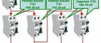
Theoretically and practically, also with the participation of specialists, installing an RCD involves taking measures to determine the device’s response threshold.
Instructing the installation of protective devices from the RCD series always requires a certain installation sequence. The first element in the sequence is usually a circuit breaker. Then come the electric meter, RCD and other network elements (+)
There are established rules - a kind of instruction, where the entire sequence of actions in such cases is noted.
Work progress:
- First of all, the load circuit in phase and zero is disconnected from the device, for which an automatic switch is used.
- Next, a diagram of connecting measuring equipment and adjustment elements (potentiometer) to the RCD is used.
- By changing the resistance of the potentiometer, the device is activated and the current readings are recorded on the measuring device.
The marked value of the measuring device at the moment of operation is the differential current of the RCD. The recorded current reading must be within the specified range.
If the condition is not met, installation of a protective device in the circuit is prohibited. It is necessary to select another copy that matches the parameters.
Setting up an already installed device is a classic phenomenon for professional services. Thanks to precise tuning, optimal protection is set, which significantly affects overall safety
When connecting protective devices such as RCDs with grounding, the rules also require work aimed at measuring the leakage current within the boundaries of the device’s protection zone.
Typically, such measures are required for installation of electromechanical devices:
- The load is connected to the protection device through the circuit breaker.
- According to the test circuit, a measuring circuit consisting of a resistance store and an ammeter is connected to the device.
- By changing the resistance store, the device is activated and the ammeter readings are recorded.
- The leakage current is calculated using the formula: Iу = I – Ia, where I is the circuit breaking current, Ia is the ammeter reading.
The resulting value of Iу should not exceed the rated value of the differential current of the RCD by more than one third.
The setup is accompanied by measurements of currents in various modes. Ammeters with a high degree of reading accuracy are used for measurements. Only specialists can do this kind of work.
If such an excess is recorded, this is a clear sign that there is a defective area within the protection zone of the device. For such cases, the rules of the PES require the implementation of the necessary measures aimed at eliminating the leakage current.
Operating principle
Since the RCD is a device for protecting people from electric shock, the principle of operation is based on the neutralization of the dangerous potential of the equipment body. The upper terminals of the device are connected to phase and zero directly from the energy generator, and to the lower terminals - phase and zero from the load. Thus, the pattern of current flow through the circuit is in the order from the source of electricity through the RCD on the wire to the electrical appliance, and then in the reverse order returns to the network.
In the circuit, the device acts as the main controller of the current that enters and exits it, respectively. If the difference is non-zero, a leak is detected, a signal about which is sent to the RCD and in less than a second the electrical circuit is turned off.
In a stable and healthy network, there is no noticeable difference between the incoming and outgoing voltage, so the controller does not operate and all connected equipment works normally. In emergency situations with current leakage, the entire electrical network stops working, preventing fire or direct contact with a person. The principle of operation is aimed primarily at safety, so the RCD does not react in any way to emergency situations that are not accompanied by current leaks, for example, to an overload of the electrical network or a short circuit in it.
Why is it necessary to install an RCD?
Let's look at this issue using a simple example. Let's say there is a washing machine in the bathroom. Electrical wiring in the apartment is made only with neutral and phase wires, there is no protective grounding, and the RCD is not installed.
Let us present the situation further. The insulating layer inside the machine was damaged, causing the phase to come into contact with the metal body. Some potential has appeared, that is, the body of the washing machine is now energized. If a person approaches it and touches it, it will play the role of a conductor through which electric current will flow. The effect of the current will continue until the person withdraws his hand from the washing machine, because the damaged area will not be turned off by any device. Unfortunately, under the influence of current, a person’s muscles are paralyzed, and it is not always possible to pull the hand away.
There are two options here - either the person loses consciousness and gives in, or someone else helps him by turning off the input machine for the room.
If, in the example considered, there was an RCD in the distribution panel, it would react to the appearance of a leakage current, turn off and protect human life. It is for this reason that in an apartment equipped with a large number of powerful household appliances, the installation of an RCD is simply necessary.
Possible installation errors
Before you start connecting, you need to know about the mistakes that are most often made when installing this type of electrical protection.
- The phase wire of the electrical wiring is always connected to the “L” terminal, and the zero wire to the “N” terminal.
- The neutral of the wiring should not be installed to bypass the system.
- If a large number of electricity consumers are connected to groups of protective devices, then it is prohibited to combine “0” of all electricity consumers.
In addition, when a protective shutdown is triggered, it is necessary to find out the reason, and only then turn on the RCD, otherwise the leakage problem will not be solved, which is fraught with repeated triggering of the protective mechanism.
Scheme options
Before connecting an RCD without grounding, you should make sure that standard circuit breakers are present in the circuit. It connects in two ways:
- at the entrance;
- to the inlet and outlet branches.
It is important that the device is connected only in combination with a circuit breaker, otherwise it will not perform its function
Input connection
This option involves including the device in a general circuit to protect all home wiring. For this method, it is necessary to connect RCDs and outgoing connection circuit breakers.
The advantages of the input connection scheme include significant savings, since only one controller is used to ensure safety. However, at the same time, there are also disadvantages. For example, when a phase is short-circuited on one device, the entire electrical network fails and the supply of voltage to all connected equipment in the apartment is stopped.
Circuit with one RCD at the input
Before choosing this option, it is advisable to weigh the pros and cons of this method of operating the device. The circuit is suitable for connecting an RCD in a single-phase system without grounding.
Connection at the input and outgoing branches
To implement this scheme, you will need several RCDs in a two-wire network. As in the previous version, one of them is installed at the entrance after the input circuit breaker, and the rest are placed immediately after the circuit breakers of the outgoing connections.
Connecting an RCD at the input and on outgoing branches
The number of required devices depends on the grouping and layout of the home electrical network. Most often, they are divided into lighting and socket sources. Sometimes a method is used to separately protect expensive and energy-consuming equipment that consumes electricity. In this case, installing an RCD in a two-wire network without grounding is ideal.
Schemes with several RCDs in a single-phase network
Another popular option is a scheme where there is protection on individual lines.
Scheme with several RCDs with wiring along lines after the meter
Many people are satisfied with the scheme shown in the figure above, since all lines are protected. At the same time, it is easy to detect a malfunction when a current leak occurs by disconnecting one line. In addition, the other network remains operational, which creates benefits. Connections of phase L, zero N to devices and ground PE, used to protect electrical appliances, are highlighted in different colors:
- blue – phase;
- black – zero;
- green - earth.
Under no circumstances should zero and ground be confused. They perform different functions, and if connected incorrectly, the phase may end up on the device body.
The next circuit in the figure below is similar to the previous one, only here there is an additional RCD at the input. The question immediately arises: why is it required? A common device is needed mainly in cases where not all lines are protected. The wire colors match the previous diagram.
Scheme with general and group RCDs
The circuit must provide selectivity of shutdown when there are several protective devices and only one should operate. First of all, the leakage current of the input device must be greater and be at least 100 mA. Selectivity is also ensured when there are devices with different shutdown delays.
The disadvantage of the scheme is the higher cost and the need to place all the equipment on a large distribution board.
Current protection does not solve short circuit problems. If this happens, the device immediately fails. In this regard, there is a circuit breaker in the same line with the RCD, which should be installed with a flow current rating one step lower.
The machines can be installed sequentially: both before and after the protective device. They do not interfere with each other and work when there are different emergency situations. The machines also operate at very high leakage currents.
Residual current settings
The installation standards for RCDs must take into account I∆n - this icon on the body means the leakage current, the value at which tripping and de-energizing occurs. Example of part of the range: 6, 30, 100, 500 mA. Sometimes it is displayed in Amperes (A), then it must be divided by 1000: 0.006 and so on. The “non-release” phenomenon, when it is impossible to tear your hands away during a current injury, appears at 30 mA, therefore, for household equipment and structures with which people come into contact, products are selected that trip at 10 mA or up to 30 mA of leakage current.
For powerful equipment, such as boilers 1...3.5 kW and above, for wet conditions (“wet” auto-protection) always take I∆n 10 mA.
But if, in addition to the high-power consumer, there are other devices on the line (their powers are taken into account together), then with 10 mA leakage there is a risk of false alarms, therefore in such situations they choose I∆n 30 mA (SP 31-110 clause A.4.15).
Trip occurs within 50–100% of the diphtoc setting. A product with I∆n 30 mA will open contacts at 15–30 mA. When protecting double or with several levels according to SP 31-110 clause A.4.2 for a device located closer to the power point (input), it is recommended that the setting and response speed (selectivity) be three times higher than near the equipment being serviced.
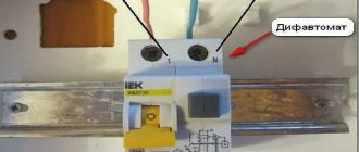
Connecting an RCD in a two-wire network
For example, a bathroom may use a boiler powered by one 16-amp circuit breaker. The installation of the heater apparently was not done very carefully. It was powered using a separately installed cable, which ran openly in the bathroom, that is, without special protection in the form of a box or corrugation. While taking a shower, the cable becomes covered with moisture. This is, of course, quite dangerous. Therefore, it is better to install a special RCD in a two-wire network.
There were two machine guns in the shield. The boiler is powered from the first, and the rest of the apartment is powered from the second. After some thought, it was decided to install its own protective device for each line. It's expensive, but very effective.
A separate cable was pulled from the shield. Then we managed to connect the lighting in the hallway. But in other rooms it was not possible to connect using this cable
In order for the device to be connected reliably, an IEK brand RCD with a rated current of 16 A was selected. Above in the article there was already a mention of basic connection errors that are best avoided. That is, you cannot combine zeros after the RCD. The connection in the panel was made in such a way that the phase went through the machine, and the zero had to be taken from the panel body. Before connecting, you need to disconnect the power cable from the switch, from the panel, or more precisely from its metal part. After installation, the connection begins. You need to immediately connect the neutral and phase of the cable to the output terminals of the device. That is, you need to connect one cable to the boiler, and another to the apartment.
The terminals of the circuit breaker are connected to the output of the device. And a zero is connected to the zero input directly from the panel body. This makes it possible to eliminate the re-combination of the neutral conductors of the wires coming out of the RCD. Thus, there is no connection with the shield body.
After completing the connection work, you can already check the device in operation. It should not operate in any false situations due to incorrect connection. To do this, you need to turn on the machine in front of the RCD. You also need to create a load. To do this, you can, for example, connect some electrical device to the network. If no shutdowns occur, then everything went successfully and correctly.
It is also necessary to remember that after connecting the RCD, it is necessary to investigate the presence of a leakage object. Using the special “TEST” button, you can check the device for operation.