Potentiometers are adjustable voltage dividers for adjusting it when supplied to a powered device at constant current. Other names are variable or tuning resistor, but it is necessary to distinguish between the rheostat mode. The resistance of the part, and, accordingly, the voltage power can be changed, thereby adjusting a specific function of the device being serviced. It is potentiometers that regulate the light intensity of lamps (dimmers), LEDs, sound (simple selectors or equalizers), the rotation speed of fans, and small electric motors. The controls for these radio components are known to everyone: rotating knobs or sliders (on old stereos, TVs, tape recorders), software solutions can be used (via microcircuits), there is also an automatic, automatically controlled potentiometer.
Potentiometer concept
In this article we will use the following abbreviations:
- PT and RS - potentiometer, rheostat;
- I - current;
- U is voltage;
- R - resistance (resistance).
Other names for potentiometer:
- resistor: trimmer or variable (trimmer, variable). These are two different types of the same part in question, they must be distinguished, but sometimes these names are used as a general name. Here we mean these parts in potentiometer mode, not rheostat mode. By default, we will assume them in this inclusion option;
- voltage divider. The name most correctly reflects the concept of what a potentiometer is.
A voltage divider is the same resistor; the part is created according to its type and according to a similar principle. But an ordinary such element (“constant” “fixed”) provides a fixed amount of resistance that blocks the current in the circuit, resisting it, thereby lowering it according to Ohm’s law.
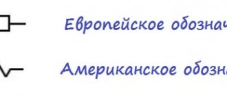
A variable/tuning resistor has a plate (like a car wiper, scraper) or similar element that runs with a constant (sliding) contact along the resistive (sensitive) part. In this way, the resistance is changed, and most importantly, the voltage is divided, that is, it is adjusted, decreased/increased. Therefore, such radio components are called “voltage dividers.” Below in Fig. Western standard part designation:
The name DC potentiometer is a combination of the phrases “potential difference” and “meter” - I measure, the term appeared at the dawn of the development of electronics and implies a measuring device. When setting up dimensional resistive coils with wire windings, the property of the part was used to measure the potential difference values, which classified it as a measuring type. So it is, it’s just that now these qualities are adapted to voltage regulation. This aspect of the application quickly became the main one and 95% of such elements, or even more, are manufactured specifically for controlling electrical parameters.
Graphic designation
According to the standard, there are several options for the conventional graphic designation (CGO) of various variable resistors.
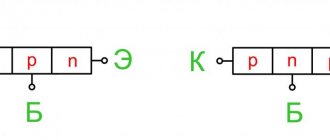
The figure shows UGOs used in Europe and Russia. The first two are a general designation, the third is a resistance with a linear characteristic depending on the angle of rotation of the control knob, the fourth is a resistance with a nonlinear dependence. The first and second types of resistors are used for switching on according to a potentiometer circuit, and the third and fourth types are used according to a regulator circuit.
The tuning resistor, the designation of which is given below, is depicted in two ways according to the standard.
The first sign denotes resistors that act as current regulators. The second method is intended for resistors connected according to a potentiometer circuit.
In the USA, Japan and some other countries, other UGOs are used.
There are no fundamental differences, but it is good to know both designations.
Features of electrical parameters adjustment
To understand the operation of variable resistors, you need to know that always - in rheostat or potentiometer mode - both voltage and current change (U depends proportionally on I). Both operating algorithms are based on a change in resistance (R), which remains independent of the specified values. But it is precisely its adjustment on the variable that reduces/increases U and I.
Voltage dividers are resistors with a fixed resistance value. (ohm number) on it, and with a variable one set by an additional lever (scraper). This is a common element of electrical circuits, electronics, and household appliances. The controls are familiar to everyone - small round knobs, sliders, sliders, selectors.
Main settings
It is necessary to select a variable resistor not only according to standard parameters - resistance, power dissipation and permissible error. As you probably already understood, you will also have to take others into account:
- Range of resistance changes. There are usually two numbers - minimum and maximum.
- Working temperature.
- Thermal resistance. Shows how much resistance increases when heated.
- Effective angle of rotation of the regulator.
Parameters of powerful variable resistors
Of course, the main parameters are important and they are the determining ones. But you should also pay attention to the temperature. If the equipment will be operated indoors, it is important that the resistor does not overheat. For equipment that will be used outdoors, the lower range is important - if operation is planned in winter, they must withstand sub-zero temperatures.
Where and for what are voltage dividers used?
PTs normalize voltage; more often they are used to adjust application parameters (serviced equipment) within the normal values for which it is designed, when such a function is built into it, for example, sound volume, fan speed. The most common model is with manual adjustment, but there is also an automatic integrated potentiometer.
PT is also used when it is necessary to establish the desired mode of equipment in difficult conditions, when a certain level of electrical parameters can disable the application, or for research, for the purposes of maintenance, repair, experiments, and adjustment.
An increase/decrease in U supplied to the load, which also entails changes in current, is carried out by potentiometers or rheostats. We will look at the difference between them below. In fact, these terms do not denote the part itself (in all cases this is a variable resistor), but the modes of its inclusion in the circuit.
The most typical examples of what is regulated:
- power and other parameters (adjustment by equalizers) of sound, video brightness/shades, light (dimmers);
- speed of low-power electric motors of household appliances and toys;
- Fans with variable speed settings have voltage dividers. Even those whose rotation intensity is meant to be set to constant operation with a certain value? often have a trimmer on the chip;
- generator frequency;
- calibration of electrical circuits, on microcircuits for adjusting electrical parameters by voltage (its output power).
- Precision, including automatic high-precision potentiometer is used in angular and linear displacement sensors.
Variables/trimmers are used wherever adjustment of the output voltage is required. But you need to understand that such a device is needed only for high-resistance loads and low currents. Where these parameters are large, rheostats are used. For example, the dimmer may contain a DC, but if the incandescent lamp is powerful, then it will be useless and a PC must be used. The same applies to electric motors: low-power ones can be regulated by PT, but powerful power plants in vehicles have RS. In order to study where to apply what, you need to do calculations using Ohm's formulas.
Features of 10 kOhm variable resistors
Today in radio markets you can find a large number of elements for drawing up a diagram. The most popular is a 10 kOhm variable resistor. It can be variable, wire or adjustable. Its main distinguishing feature is single-turn operation. This type of resistor is designed to work in an electrical circuit where there is direct or alternating current.
The power rating is 50 volts and the resistance is 15 kOhm. These elements were produced in the mid-eighties, so today they can be found not only in specialized stores, but also in old radio circuits. The 10 kOhm variable resistor has several functional and possible analogues.
Potentiometer and rheostat: what is the difference
Let's consider RT in detail, since the properties of potentiometers will also be revealed in the process. So, the same variable resistor can be mounted on the circuit in two ways, creating two modes:
- parallel connection - PT. The potentiometer connection usually uses all 3 pins.
- sequential - rheostat. Only 2 contacts are used.
“Potentiometer” and “rheostat” are simply different options for including the same variable resistor in a circuit, respectively, in series or parallel. Both parts work specifically with R, U, I. But the proportionality of the changes is different, in the first case the voltage is regulated to a greater extent, in the second - the current.
The rheostat has two outputs, the potentiometer has three (if used as the first, then only two contacts are connected). That is, the PC is included in the circuit like an ordinary resistor. Both are non-polarized and can work in reverse.
PT and PC are connected differently. The second, unlike the first, is usually an industrial device or on powerful equipment. Some schools taught lessons with a rheostat, so some may remember its shape: a large ceramic tube with a nichrome winding and a slider on the middle terminal that is not connected anywhere. RS has high power (passes powerful current) and low resistance (up to tens of ohms). It has significant inductance, which is taken into account in HF devices.
Voltage dividers are usually low-power, so they are rarely suitable for the role of PCs; in production, variables up to 10 W are positioned as the first, and from 10 W - as the second.
Variable as a rheostat
RS changes the overall resistance. circuits - it is this property that is important here; it is used in its full, most effective form to control (limit) the current.
It is connected to the circuit only in series: the switched-on variable is called a rheostat (this is the operating mode).
You can imagine the circuit as such, consisting of two ordinary resistors connected in series, that is, the slider divides the PC coil into the indicated elements. By adjusting R, the parameters of these resistors and, accordingly, the current in the circuit are reduced/increased.
What is a resistor with variable resistance
Among radioelements, there are parts that can change their main parameter. This is what variable or adjustable resistors are. They differ from constant ones in that their resistance can be smoothly changed from almost zero to a certain value. The change occurs by mechanically moving the slider.
Adjustable or variable resistors - different types and sizes
There are varieties of variable resistors - trimming and adjusting. What is the difference between variable resistors and trimmers? Because the trimmers are designed for a small number of adjustments. For some models, their number can be in the hundreds or tens (for example, for the HP1-9A, you can move the slider no more than 100 times). If you look at the table below, you can see that some SMD trimmer resistors have only 10 adjustment cycles.
Example of characteristics of SMD trimming resistors
For variable resistors this figure is much higher. The number of movements of the regulator can be in the tens and even hundreds of thousands. So it’s clearly not worth using trimming resistors instead of variables.
The main disadvantage of variable resistors is their fragility. The contact between the resistive layer and the brush gradually deteriorates. For acoustic equipment, this can be expressed in ever-increasing noise; when adjusting the frequency in radio receivers, it becomes increasingly difficult to “catch” the desired wavelength, etc.
The animation makes it clear how a variable resistor works and why it fails
Variable resistor as potentiometer
An appropriate and more correct other name for PT is a voltage divider. If we take the above diagram, then these are also 2 or more resistors with a serial connection, but such a node of them (chain) is connected in parallel to the source, which allows adjusting their resistance to obtain exactly the voltage required for the load.
Difference in scope
The potentiometer has low power and is used for relatively low-power devices: TVs, audio equipment, low-power dimmers, underfloor heating controllers, boilers, as converters, for adjusting the speed of weak motors, for fans, for example, computer coolers, ventilation systems.
We will characterize the use of RS with a selection from a thematic site:
The areas of use at first glance are similar to PTs, but this is not the case: RSs are used where there are high currents and the operation of devices depends on them: powerful power tools, electric motors of vehicles and production ones, in industry.
We can say that the alternator for lamps operating with high currents and the same loads in the form of electric motors, for electric furnaces, and machine tools is used only in rheostat mode.
The clearest explanation for the difference in application
With a potentiometer, the current from the source is spent several times higher than the load needs. At PC, the value of this value is equal to that at the load. Therefore, the latter is used to adjust I and U on low-resistance loads, they have a pattern - they consume relatively more powerful currents, and potentiometers - for high-resistance loads, since they are usually powered by this value with a small value.
Features in appearance
The variable can be both, but if it is manufactured for rheostat mode, then it has a typical size for it: with two terminals, with a large resistive part (winding), usually a large, thick, heavy wire resistor and its shape is much larger, what about the parts for PT.
It is necessary to distinguish between terms, since sometimes confusion arises in different sources: for example, the phrase “potentiometer in rheostat mode” is not entirely correct, since this designates two different connections, but the phrase “variable resistor in rheostat (or potentiometer) mode” is correct. Although erroneous lexical formations are often found even on technical websites, the main thing here is that the user distinguishes what is being said.
If a part has two outputs, then its state is only PC, but if there are three, then such a part can theoretically be used as it (we described this above), but in reality it is intended specifically for the DC mode.
Trimmer resistors.
Trimmer resistors are a type of variable and are used for one-time and precise adjustment of electronic equipment during its installation, adjustment or repair. As trimmers, both variable resistors of the usual type with a linear functional characteristic, the axis of which is made “under a slot” and equipped with a locking device, and resistors of a special design with increased accuracy of setting the resistance value, are used.
For the most part, tuning resistors of a special design are made of a rectangular shape with a flat
or
a ring
resistive element.
Resistors with a flat resistive element ( a
) have a translational movement of the contact brush, carried out by a micrometer screw.
For resistors with a ring resistive element ( b
), the movement of the contact brush is carried out by a worm gear.
For heavy loads, open cylindrical resistor designs are used, for example, PEVR.
In circuit diagrams, tuning resistors are designated in the same way as variables, only instead of the control sign, the tuning control sign is used.
Algorithm for the operation of a potentiometer, comparing it with that of a rheostat
It is appropriate to reveal the principle of operation simultaneously for PT and RS, since we are essentially talking about one part in different modes:
The principles of operation are revealed by the laws of the process of changing current and voltage. For the rheostat, let's take a light bulb as the load (in the diagrams above). With increasing resistance on PC the same thing happens with the general resistance. (Rtotal), and the same current decreases. Consequently, both I at the load and the voltage across it drop.
The decrease/increase in current in the circuit is not inversely proportional to that of the resistor. RS, because in addition to the adjustable R rheostat, there is also R, but unchanged - at the load. Only when Rreost >>Rн will these quantities change with close to inverse proportionality. On the contrary, if Rreost
Now we will explain the action in the process of describing how U of the load changes: the total value at the current source (Uist = Un + Upeost) between RT and U is proportional to their R:
When this decreases on the PC, a redistribution of the total U occurs and at the same time the U of the load, and, consequently, I through it increases.
Now let's move on to the potentiometer. This is the same rheostat, but connected differently and the name “voltage divider” most accurately reflects its essence.
The PT regulates current and voltage on high-resistance (we focus on this) equipment, that is, with this parameter, the use of RS is inappropriate, if not completely impossible. A variable resistor as a PT is connected to the source by the lower terminals A and B, which are the ends of the winding, enclosed (crimped) in a way convenient for inclusion in the circuit. Unlike a PC, terminal C is connected to the consumer and A and B are also connected to it.
Operating principle of PT:
- voltage is applied to the entire resistor;
- but for the consumer only part of it is removed, which can be adjusted by moving the slider D between points A and B;
- in this case, the indicated load value Un will vary from 0 to the maximum U of the source.
U at the consumer can fluctuate in direct proportion to the length of the segment ^AC, but it can also have a more complex relationship U = f(l), determined by the ratio of R load and R potentiometer. There are such patterns:
Purpose
Resistors are a passive element of an electrical circuit that does not convert energy from one type to another. They have active resistance. Their main characteristic is nominal resistance. No less important is a characteristic such as power.
Variable resistors can change their resistance using an accessible adjuster. Act as a current or voltage regulator.
Trimmer resistors have a control that changes the resistance, but it is not available for manual adjustment. To do this you need to use a special screwdriver. These resistors are used only for setting the operating modes of a technical device and are not intended for frequent use.
Calculation, selection of potentiometer parameters
So, the potentiometer is designed to regulate the voltage specifically on a high-resistance load - it must have resistance. higher than PT, otherwise the number of Volts will be determined by it, and the adjustment function will disappear.
The main features for calculating PT are:
- resistance The PT should be much smaller (Rpot<<Rн) than that of the load. This is not necessary, but if not observed, further calculations will become more complicated - you will have to take into account the current on it. The recommended values are at least 10 times lower, but better - 20, 30, 100. The lower, the better, but not excessively, otherwise the requirements of the following points will not be met;
- U of the current source must be suitable, the PT must withstand it (Inom.pot×Rpot) > Usource. In this case, the number of Amperes flowing through the alternator (Ipot = Uust/Rpot) should be less than the current rating of the part;
- the current passing through the PT (Ipot = Uust / Rpot) should not be higher than the nominal value according to that of the source (Ipot < Inom. source);
- if there are several PTs and they all fit the above conditions, then take a product with higher resistance - it will consume less current, which is especially significant when used with galvanic batteries.
Another nuance of adjusting current and voltage with a rheostat and potentiometer:
- both make it possible to obtain U at the load equal to or lower than U of the source;
- but with PT you can lower the above value to 0, which is extremely difficult, almost impossible, to achieve from RS.
The Importance of Power Dissipation
When selecting a variable resistor, the resistance rating is taken into account first, but current rating, in other words, power dissipation, is no less important to pay attention to. The two parameters are interrelated. Let's explain with an example. The circuit contains a resistor with a certain R, but it turns out that this value should be significantly lower, that is, the part must be replaced.
They put in an element with a significantly lower R, and it would seem that the problem is solved, but here there is a danger associated with ignoring Ohm’s law. R on the resistor was significant, U of the circuit was fixed. When the value of the variable was lowered, the total R of the line fell, as a result, the current increased. If you install a PT with the same dissipation power, then with increased I it may not withstand the load, the consequences are traditional - overheating, even to the point of fire.
Approximate norm: with a nominal value of 10 Ohms, a current of about 1 A should flow through the circuit - this is the power dissipated by the resistor. When choosing, be sure to look at this permissible value for the part.
Types of potentiometers and their characteristics
In modern electronics it is common to use the following types of devices:
- products with unipolar power supply;
- bipolar power products;
- mechanical products;
- electronic products.
Single Supply Potentiometers
Such products are equipped with special rheostat keys. All types of resistors in this case must be used only of the passive type. The moving contacts of the device have high conductivity of electric current . The value of the electronic key's bandwidth directly depends on the cutoff frequency. This parameter usually does not exceed 2100 kilohertz. Similar characteristics of potentiometers are very often used to adjust tone.
Bipolar Potentiometers
Dual power products are used only in computing products. The main feature of such devices is the high level of maximum resistance. Electronic keys for such equipment must be used only of the rheostat type. At the bottom of the product there are several terminals for connecting to the electrical circuit. The device is configured using special bridge equipment. The resistance spread does not exceed two percent. The negative electrical voltage of the device is no more than 4 volts.
Mechanical potentiometers
A mechanical potentiometer is a product for regulating electric current , which is equipped with a special rotary controller. There are several pins at the bottom of the device. Electronic keys must be of the resistive type. And also in such products a program sampling function is provided. The maximum value of through resistance does not exceed 4 Ohms. Such products are not equipped with a calibration function. The negative electrical voltage of such a device is about 4 volts, and linear distortion does not exceed 92 decibels.
Powerful resistors should only be used of the open type. Mechanical potentiometers are ideal for reversing control. Many products do not support rheostatic mode. It is worth noting that such devices are not used to control the gain. The maximum positive electrical voltage is about 2.5 volts. The cutoff frequency very rarely exceeds 2500 kilohertz . The bandwidth value is directly dependent on the characteristics of the electronic key. Such products are not usually used in computing devices.
Electronic potentiometers
An electronic potentiometer is a product necessary to regulate electric current. Many models are equipped with several electronic keys. Powerful resistors should only be used of the resistive type. To reverse control the equipment, you can use almost any product model. These devices can withstand up to 12 continuous control cycles. Almost all models have a software sampling function. It is worth noting that electronic products can be used to control volume. The value of linear distortion of such devices does not exceed 85 decibels .
Electronic products are quite often used in computing equipment, because their cutoff frequency is no more than 3100 kilohertz. The bandwidth of the electronic key is about 4 microns, but it largely depends on the manufacturer. Many models of such potentiometers are used for high-quality adjustment of various filters. It is worth noting that this device cannot perform gain adjustment.
Design and types of variable resistors
A potentiometer is primarily an analog electromechanical part; there are also digital types, but they are still not very common. The wiper can also be moved using electrical means, not only manually. Movement can be angular (rotation) or linear (straight); Usually it is manual, but there is also an automatic, application-configurable potentiometer.
Potentiometer structure (the first two parts are main):
- resistive element;
- a plate (wiper, scraper) with a sliding contact moved by a handle (selector, lever) along the above part;
- terminals at each end of the part;
- mechanism that moves the wiper (shaft, slider block), bushing, bearing
- a housing in which the resistive part is enclosed.
The described device can be taken as a general principle, which is implemented in one form or another in all types of radio components; string and digital PTs are also based on it, but with their own specifics.
The resistive part of inexpensive variables is often made of graphite. Sensitive wire, plastic with carbon particles, and a mixture of ceramics and metal (cermet) are also used. For options with conductive tracks, polymer conductive pastes with carbon, wear-resistant resins, solvents, and lubricants are used. To summarize, according to the design of the case, the potentiometer has its own types and types in the form of pots (barrels, boilers), strips and chips (trimmers).
According to the material of the sensitive part
Wire - Constantine or Manganin wires are laid evenly in a horseshoe in the body. The slider slides along the turns, touches the next one before leaving the previous one - this is how smooth adjustment is achieved.
Thin film. The sensitive part is a horseshoe-shaped frame of a dielectric plate with a thin film: carbon, boron, metallized, composite materials. Trimmers and trimmers are often like this
By number of contacts
There are single-element models - these are standard variables. There are multi-element ones - double, triple, and so on - then there are more contacts for each such part. There are also products with contacts for the switch (below in the figure).
Rotary (circular, disk) variables
The most common variables are rotary ones. They can be equipped with a switch, usually triggered in the extreme counterclockwise position. Thus, you can immediately, without a separate element, turn off/on radio receivers such as equipment: for example, the device starts after a click when turning the selector at minimum volume, then it can be increased.
Pins 1 and 2 are also on regular resistors - of a constant value. Resistance is created by a special coating, an array of conductive alloy (including in the form of film, spraying), and a wire winding (nichrome and the like) on the “body” between them. For variable type, a third terminal is added (for the scraper), connected to the “engine”, a movable plate (wiper), moved with a sliding contact along this segment; for rotary types it is in the form of a horseshoe (arc).
If you turn the knob, R changes between 1 and 3, from 0 to the value stamped on the device body. The same thing happens between 2 and 3 “upside down”: when R between 1 and 3 increases, then between 2 and 3 it decreases and vice versa.
Linear, with sliders
Linear (sliders) have the shape of a plate, bar, that is, a longitudinal resistive element. The adjustment tool is a slider that slides along rather than rotating. The disadvantage of such models is that they are less protected from dirt: dirt can get inside through any part of the slot, even though there is a slider seal. The advantage is better visualization of the settings indication.
For rotary models, the position of the handle is often impossible to determine, especially if a “bare” resistor is mounted - for this you need to do calibration. If there is a scale, then it is perceived less conveniently. On the linear type, the setting position is visible even without the indicated one - by the position of the slider. For example, for equalizers and faders, you can determine the adjustment positions, evaluate the overall picture of the settings of a dozen or more sliders on the control panel, without looking too closely. In addition, linear FETs are usually more accurate because the resistive part is longer.
Multi-turn
A conventional circular variable makes complete movement of the adjusted point in 1 turn of the adjustment screw and is incomplete; the horseshoe should not close. For some tasks they are not accurate enough. For special sensitivity there are multi-turn options. They complete the described cycle in a certain number of revolutions, which greatly reduces errors. For example, turning the selector of a single-turn model with a nominal value of 10 kOhm half a turn will change the resistance. at 5000 Ohms, if the tolerance is 10%, then it will give an error of 500 Ohms. Multi-turn potentiometer 10 rpm with the same parameters, with a similar rotation of the lever, it gives a deviation of only 50 Ohms - 0.5% of the nominal value.
On average, turning the selector by the same angle gives an accurate setting one-tenth better than single-turn models.
Strings
A special subtype are string voltage dividers; they are controlled by a flexible cable and a spring-loaded coil. They are used for measurements on moving objects, for measuring linear position in industry, manufacturing, medicine, robotics, and on automated production lines.
Particularly accurate
Rotary or linear PTs with fixed positions marked with clicks are special discrete precision models made up of several resistors. They are used in testing equipment and on particularly precise equipment.
Automatic
The adjustment is not done manually, but by automatic application.
Twin
Several resistors can be located on the same shaft with their sliding scrapers, which makes it possible to regulate 2 or more channels in parallel. Used in audio amplifiers.
Trimmers (trimmers, presets)
Trimmers, also known as trimmers or pre-installed ones, are standard sizes for soldering onto a board. When a manufacturer creates a microcircuit, the part is soldered in and the required position is immediately set. It is assumed that it is the best for the device and it is not recommended to change it, except for the purposes of repair or special configuration cases.
Although there are also parts that require constant adjustment, for example, when such a standard size is appropriate for a particular device.
Digital
Digital PTs are becoming popular, which are integrated circuits without moving parts that allow you to adjust your own R programmatically with a given step.
Types of Potentiometers
Variable potentiometers are an analog device consisting of two main mechanical parts.
1. A fixed or stationary resistive element, track or wire coil that defines its resistance value, such as 1 kOhm, 10 kOhm, etc.
2. The mechanical part that allows the contact to move along the entire length of the resistive track changes its resistance value as it moves. There are many different ways to move a contact across a resistive track, either mechanically or electrically.
But along with the resistive track and wiper, potentiometers also contain a housing, a shaft, a slide block, and a bushing or bearing. The sliding contact movement itself can be a rotary (angular) action or a linear (direct) action. There are four main groups of variable potentiometer.
Rotary potentiometer
A rotary potentiometer (the most common type) changes its resistance value as a result of angular movement. Rotation of a knob or dial attached to the shaft causes the internal contact to move around the curved resistive element. The most common use of a rotary potentiometer is as a volume control.
Carbon rotary potentiometers are designed to be mounted on the front panel of a housing, enclosure, or printed circuit board (PCB) using a ring nut and lock washer. They can also have one single resistive track or multiple tracks known as a group potentiometer, in which all rotate together using one single rod. For example, a pot with two gangs for simultaneously adjusting the left and right volume levels of a radio or stereo amplifier. Some rotating pots have switches.
Rotary potentiometers can produce linear or logarithmic output with tolerances typically ranging from 10 to 20 percent. Because they are mechanically controlled, they can be used to measure shaft rotation, but a single-turn rotary potentiometer typically offers less than 300 degrees of angular movement from minimum to maximum resistance. However, there are multi-turn potentiometers called trimmers that provide a higher degree of rotational accuracy.
Multi-turn potentiometers allow the shaft to rotate through more than 360 degrees of mechanical movement from one end of the resistive track to the other. Multi-turn pots are more expensive but very stable with high precision, used mainly for trimming and fine adjustment. The two most common multi-turn potentiometers are 3-turn (1080 o) and 10-turn (3600 o), but 5-turn, 20-turn, and higher 25-turn pots are available with a variety of ohmic values.
Types according to the “cone” - the nature of the change in resistance
“Cone” or “law” is the relationship between resistance. and the position of the scraper. Manufacturer controlled. Any ratio is possible, but for most tasks linear and logarithmic PTs (“sound cone”) will suffice.
A letter code may be used, but this is not standardized; it may be different for different manufacturers, but usually the marking is as follows:
- Asia and the USA. A - for logarithmic, C - for inverse logarithmic (rare, exponential) and B - for linear taper;
- Europe - A for linear, C and B for logarithmic, F for its inverse version.
Explanation
The percentage relating to the non-linear cone refers to the resistance index. at the midpoint of shaft rotation. The 10% cone of a log measures 10% of the total R on it. That is 10% logarithm. a cone on a 10 kOhm PT gives 1 kOhm at the indicated mark. The higher the percentage, the steeper the logarithm. curve.
Resistor markings
In technical documentation, trimming resistors are always indicated in full. There is no unified marking system for trimmer resistors. Abroad, they have developed their own rules that do not coincide with ours. In Russia, the standard for variable resistors is GOST 10318-80.
The marking of trimming resistors contains the letters RP at the beginning of the designation - variable resistor. This is followed by the number 1 (non-wire), or 2 (wire). After that, the product development number is indicated through a hyphen. For example, RP1-4 should be read as follows: variable resistor, non-wire, model number 4.
After this, the permissible power in watts is indicated through a hyphen. For trimmers there is a standard range: 0.01; 0.025 and so on. A number of operating voltages are also defined. The standard provides a number of permissible deviations from the nominal resistance. Using all its positions, write down the resistor coding.
How voltage dividers are shown in diagrams
In order for the reader to distinguish the details more deeply, we indicate the graphics for PT and RS.
Designation of rheostats:
Designation of voltage dividers:
Designation of a simple (fixed) resistor:
The principle of operation of a car heater resistor
Car heater diagram
A regular VAZ stove has four speeds. As we can see from the figure, the rotation speed of the stove motor depends on the resistors. The resistor switch is the heater speed switch. In order for the air entering the cabin from the stove to be warm, the engine must be warmed up. Drivers often turn on the heater to cool the engine if it overheats.
If there is no need to heat the car interior (in warm weather), then air is pumped into the cabin directly, bypassing the heater radiator, through the heater filter. For this purpose, there is a special damper, which is switched from inside the car by the driver.
Knowing the connection diagram of the stove resistor, you can easily replace this resistance if it fails. You can do this yourself, rather than paying a lot of money at a car service center.
Did you like the article? Tell your friends: Rate the article, it is very important for us:
Voted: 6 people. Average rating: 4.5 out of 5.
Potentiometer connection
To begin with, we present a block of the most typical schemes. It must be said that the PT can be connected not only as a PC, but also as a simple fixed resistor (options in Fig. 3):
Below are the most common schemes (notations according to Western standards):
It must be said that the traditional wiring diagram for a potentiometer frequency switch always recommends connecting an “extra” pin; a break in the “moving contact - horseshoe” line is not excluded, which can lead to unpleasant consequences.
The diagrams for how to connect a PT are extremely simple; in fact, there is only one option - in parallel to one of the power wires.
For example, this is what the regulator on a computer cooler looks like. In this case, polarity does not matter. Take any cooler power supply wire, cut it, one end is soldered immediately to the first and second (middle) contacts, the second to the remaining one. That is, on the first 2 contacts there is one end of the wire (they are soldered to the same conductor), the third contact is the other end, as if standing alone.
The complexity of some circuits: you need to know which wire to connect to, that is, which power line to regulate, for example, if you are connecting an external potentiometer for variable-frequency electric drives to adjust the intensity of rotation of electric motors, when adjusting PID controllers.
In such cases, they are guided by the schemes of the manufacturers or authors of such improvements, the recommendations of the masters; all the information is available online on special forums and thematic sites. Below is an example of connecting to a frequency converter:
How to check serviceability with a multimeter
To measure resistance you will need a digital multimeter. In order to measure resistance, we need to turn the knob to “measure resistance”. Using a stick, we can twist the resistor clockwise or counterclockwise, thereby changing the resistance between the middle contact and the two outer contacts. Rules for measuring resistance:
- Press the probes with some force onto the resistor terminals. In this way, you will eliminate the appearance of contact resistance, which, when pressed lightly, will add up to the measured resistance.
- When measuring the resistance of a resistor on a printed circuit board, double-check that the board is de-energized. Then unsolder one end of the resistor and then measure its resistance.
- Do not touch the resistor leads when measuring its resistance! The average human body has a resistance of about 1 KiloOhm and depends on many factors. Therefore, by touching the resistor terminals when measuring resistance, you introduce an error into the measurements.
- If you want to measure the resistor's resistance as accurately as possible, clean its terminals either with a knife or with the mildest sandpaper. In this case, you will remove the oxide layer, which in some cases introduces a noticeable error in the resistance measurement.
Do not measure resistance under voltage! This could damage the multimeter or cause you an electric shock!
We place the probes at the extreme contacts. We measure the total resistance of the variable resistor. In order to check whether it is working, turn the variable resistor knob all the way counterclockwise and measure the resistance between the left and middle contacts. It should be close to zero.
Checking the tuning resistor with a multiprobe.
Next, turn the handle clockwise, but not all the way. We measure the resistance again between the middle and left contacts, then between the middle and right. The total should be the result of the resistance of the two extreme contacts.
We also suggest reading interesting material about little-known facts about DC motors in our other article.
Examination
Checking the potentimeter is done with a multimeter:
- the resistance measurement mode is set, the probes touch the two outer contacts - the tester should show a value equal to the nominal one with a permissible deviation. Move the slider and observe how R changes on the multimeter display;
- the wire winding may be torn, the contacts may come loose - then the break is checked as standard - the tester is set to “continuity”, the two outer contacts are touched with probes: 1 - break; 0, digital values tending to it or beeping (if there is a buzzer) - the circuit is intact.
Types and varieties
According to the installation method, there are 2 types of trimmers - for surface mounting and surface mounting (SM).
The first ones are large-sized; wall-mounted installation does not impose any special restrictions on the size of the elements. The latter are small-sized, and high demands are placed on their size. It should be borne in mind that the industry does not produce wirewound trimming resistors. Single-turn resistors differ in the location of the control, which is usually accessible only with a special screwdriver. It can be located on the side or on top. It all depends on the position in which it is more convenient to access it. The body shape is usually cubic, less often cylindrical.
Multi-turn trimmers come in mainly two types - with a cubic and oblong body shape. The control can be located on the top or side, depending on the design requirements of the device.
There are other varieties of these resistors, but for this you need to refer to reference publications.
How to choose
The process of how to select a voltage divider involves studying the following parameters (some of the data is in GOST 10318):
- priority, ratings for: resistance;
- to the utmost slave tension;
- by power (dissipation);
- tolerance (errors);
Types of resistors
Resistors come in three types:
- Constant - the resistance value of which does not change. It should be noted that small changes do occur due to temperature changes. But these changes are not significant, since they do not affect the operation of the circuit.
- Variables - their resistance varies within certain limits. For example, rheostats. When we turn a radio knob to change the sound or move a slider, we change the resistance of the circuit.
- Adjustable - change the value using a screw. This is rarely done to obtain the desired circuit parameters.
How are they labeled?
Traditional markings, known since Soviet times: PTP, PLP, PPML, PLP, RPP, PPBL, PPMF. What should be indicated on the product is regulated by GOSTs 9245, 8.478-82. The alphanumeric characters themselves are found in OST 11.074.009 (current), GOST 13453 and 3453 (outdated).
New marking:
But it must be said that in modern conditions there is no single standard, so you need to look at the product specification from the manufacturer.
Device
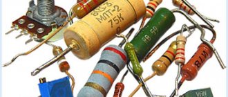
There are a large number of various designs of variable and trimming resistors with a power from tens of watts to several milliwatts. Some of them are shown in the photo below.
Trimmer resistors have almost the same structure as variables. They consist of movable and fixed parts placed in a common housing. The fixed part is a plate made of an insulating substrate, onto which a conductive layer is applied in an open circle. The ends of this layer are connected to two contacts.
The moving part acts as a current-collecting spring contact mounted on the axis. This ensures reliable connection with the conductive layer.
A slightly different device has a multi-turn trimmer resistor. It has a conductive layer applied to a straight rod, and the current-collecting contact moves parallel to it on a screw rod.
These two methods of changing resistance are used in all types of trimming resistors.
Repair
If a contact falls off, it can be soldered, but this is usually difficult to do, much less it is impossible to repair a mechanically damaged track or wire. In case of such breakdowns of functional parts, especially the resistive segment, the variables are not repaired.
If the functional parts are without mechanical damage, then you can try the following methods:
- restore the sensitive track: o lightly bend the spring of the movable contact with the lead of a simple pencil (consists of carbon) and draw along the sensitive layer. Method for thin film models;
- o grind the same stylus, mix with lithol or a similar lubricant, lubricate the path along which the slider walks;
Cleaning the trimmer with regular alcohol
The resistor in circuits can become dirty; its slider track becomes covered with a layer of dust over time. And in order to return the electrical resistance to its previous performance, you just need to clean it.
Cleaning trimmer resistors is quite simple and quick. It is best to use pure alcohol for these purposes. It is better not to use various products such as nail polish remover, moonshine, or cleaners, as they may contain impurities that negatively affect the cleanliness of the resistor.
To better master the material, we also recommend reading the following material: everything you need to know about stepper motors.
So, we disassemble the resistor (if it has a protective casing), for this it is usually enough to unbend the small metal clips on the resistor body itself, after which you need to remove this cover. Inside the resistor we will see a track along which the slider of the middle terminal of the resistor moves. It is this path that needs to be cleaned from dirt with alcohol.
It’s convenient to do this: take a syringe (let’s say 2 cc), fill it with alcohol, and carefully apply a few drops through the needle of the syringe directly onto the resistor track. After this, we begin to rotate this resistance in different directions so that the alcohol spreads throughout the entire track and thereby clears the way for the slider.
How to clean a resistor at home.
In principle, this is enough so that after assembling and installing the tuning resistor in our circuit workplace, we can enjoy its normal operation without previous problems. Although, if space on the resistor itself allows, you can also carefully go over it with a cotton swab, which will completely remove all dirt from the slider track.
It will be interesting➡ Designation of chokes on the diagram
Well, then we need to put our updated resistor back together and put it in our workplace. In most cases, after such cleaning, the electrical resistance is completely restored, and the intermittency of its operation disappears.
Difficult cleaning cases
In very rare cases, it is not a matter of dirt, but, for example, the destruction of this path as a result of excessive overheating. This can happen when too much voltage is accidentally applied to this resistor and the power of this resistor is not large enough to quickly dissipate the generated heat from the high current. This is where the variable resistor track heats up greatly, followed by its destruction. Cleaning with alcohol won't help here.
This resistor needs to be completely replaced with a new one that is known to work. And, of course, before installing a new resistor on the old circuit, check it so that the process of destroying the track does not repeat with a new resistance.
Unfortunately, not all types of variable and trimming resistors can be cleaned using the above method. Sometimes there is resistance in the solid body, which makes it impossible to reach the slider track.
Here you can go to extreme measures. Make a small hole in the body (with a 0.8-1 mm drill). Well, pour alcohol through it with a syringe through a needle. Next, again turn the resistor knob in different directions and then you need to wait until the alcohol has completely evaporated.
You can warm up this variable resistor a little (up to 50 degrees), this will speed up the evaporation of alcohol. Although pure alcohol is a dielectric, it does not conduct current through itself. Consequently, it will not negatively affect the operation of the variable resistor, even if there is some alcohol left on it, which will still evaporate.
Parallel connection
Parallel connection is also one of the main resistor connection schemes. To connect two resistors in parallel:
- the first contacts of both resistors are soldered together and connected to the positive of the power source;
- the second contacts of both resistors are soldered together and connected to the negative side of the power source.
If you need to connect more resistors, proceed in the same way (see figure). The total resistance in a parallel connection is found by the formula: R1*R2*…*Rn/R1+R2+…+Rn.