Electricity is a dangerous substance that can cause many problems if not handled correctly. For example, if an electrical device shorts out and you touch it, a charge of current will pass through your body, which can kill.
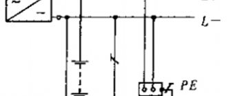
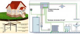
To minimize the risk of electric shock, as well as to protect electronic equipment from overloads, electrical networks are grounded, creating a circuit in which excess energy goes directly into the ground. This is precisely why grounding is necessary in a private home, country house or any other place where electricity is used. Below is a diagram of how to properly create a grounding loop.
Why is grounding needed?
When a short circuit occurs, the temperature of the conductor will rise sharply, causing melting of both the insulation and the conductive strands themselves. If you touch the wires at the moment of a short circuit, current will flow through the body, which can be fatal. This happens because the current always tends to follow the path of least resistance - that is, into the ground.
Grounding is a path that directs electricity directly to the ground, where it cannot harm anyone. The current always chooses the path with minimal resistance, and the ground loop has exactly this property. When a power leak occurs, the excess is immediately sent to the ground loop. Thus, even if a person receives an electric shock, it will not be severe, since most of the electrical energy will go through the grounding system.
It turns out that grounding is an important component of the electrical safety system. It must be said that grounding is a necessary part of any objects that use electricity. According to the requirements of regulatory documents, any building containing alternating current networks with voltages over 100 W must be equipped with a grounding system.
Grounding not only ensures safety, but also protects household appliances. The grounding loop takes on excess load during network fluctuations, reduces the impact of interference and neutralizes the negative effects of electromagnetic radiation.
Protective grounding and other measures for indirect contact
The rules for the protection of electrical installations state that to protect against electric shock in the event of insulation damage, the following protective measures for indirect contact must be applied individually or in combination:
- Protective grounding.
- Automatic power off.
- Potential equalization.
- Potential equalization.
- Double or reinforced insulation.
- Ultra-low (low) voltage.
- Protective electrical separation of circuits.
- Insulating (non-conductive) rooms, zones, areas.
As you can see, there is such a thing as protective grounding during indirect contact. We are not interested in other protection measures, except for automatic power off, in this topic. And in addition to protective grounding, there is also working grounding.
Therefore, at this stage, let’s define the terminology:
- Grounding is an intentional electrical connection of any point in the network, electrical installation or equipment with a grounding device.
- Protective grounding is grounding performed for electrical safety purposes.
- Working (functional) grounding - grounding of a point or points of live parts of an electrical installation, performed to ensure the operation of the electrical installation (not for electrical safety purposes).
- Indirect touch is electrical contact of people or animals with exposed conductive parts that become energized when the insulation is damaged.
We are more interested in electrical safety. Therefore, when talking about how grounding works, we will consider protective grounding paired with automatic power off. But you need to understand that grounding, in addition to protective, can also be operational.
The difference between a lightning rod and grounding
Do not confuse grounding with a lightning rod. Despite the fact that they operate on a similar principle, their tasks are different. A lightning rod is needed to receive a discharge from lightning and transmit it through a ground loop isolated from the internal network directly into the ground.
Grounding, in turn, serves to drain current from the internal home network in case of overload. In principle, grounding and lightning rods can have a common external circuit, subject to compliance with safety regulations. By the way, you can buy ready-made lightning protection kits that comply with all the rules and conditions for efficiency and safety.
Connecting an RCD in a two-wire network
For example, a bathroom may use a boiler powered by one 16-amp circuit breaker. The installation of the heater apparently was not done very carefully. It was powered using a separately installed cable, which ran openly in the bathroom, that is, without special protection in the form of a box or corrugation. While taking a shower, the cable becomes covered with moisture.
This is, of course, quite dangerous. Therefore, it is better to install a special RCD in a two-wire network.
There were two machine guns in the shield.
Ground loop device
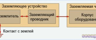
Grounding is a special conductive structure made from materials with low resistance. The grounding system consists of two circuits connected to each other using a distribution board. The first loop is located in the building and is designed to transmit current to an external ground loop, most of which is underground. A grounding loop is made from large cross-section metal rods, which ensures instantaneous current transmission.
Grounding in a private house is:
- An internal circuit consisting of an extensive network of wires that connect to sockets, high-power devices and conductive channels (pipes). The individual conductors are combined into one core, which is connected to the external ground loop.
- External grounding. Several electrodes are deepened into the ground, connecting them with metal plates. The plates, in turn, are connected to the distribution board using a massive busbar.
The operating principle of grounding is quite simple - when excess voltage accumulates in conductors or devices, the circuit acts as a kind of fuse, quickly discharging current through a common circuit into the ground. Thanks to the almost unlimited capacity that the earth has, such a circuit allows you to utilize enormous voltage.
Causes of electric shock
A person can receive an electric shock in the most common everyday situations:
- While the washing machine is running, you can sometimes feel a slight tingling sensation. Sometimes the blows can be much stronger. This is the effect of electricity on humans.
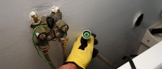
- While in the bathroom and touching the metal parts of the faucet, you can feel a slight tingling and even strong goosebumps inside your fingers.
In both cases, ungrounded objects can pass current through themselves, that is, charged particles, which, depending on the force and voltage, can manifest themselves in the form of tingling or strong shocks, accompanied by muscle cramps.
It is clear that this is extremely dangerous - in extreme cases, an electric shock can cause paralysis and cardiac arrest. However, such incidents can be avoided quite simply by grounding the bathroom or machine. In this case, the current entering the housing will flow through the grounding conductor into the ground.
Types of ground loops
To ensure the fastest and most stable flow of current into the ground, several electrodes are dug into the ground and connected using a thick busbar. The effectiveness of grounding largely depends on the location of the electrodes. By correctly positioning the conductive frame, you can speed up the absorption of current by the ground, thus improving the efficiency of grounding a private house.
There are 2 types of ground loops, each of which has its own advantages:
- Triangular outline. This type of grounding consists of 3 electrodes, which are first buried in the ground and then connected to each other in such a way as to form a triangle. The gap between the electrodes should be equal to the same depth to which the grounding pins are dug in, or slightly exceed it.
- Linear ground loop. To make linear type grounding, the electrodes are installed in one line or in a semicircle. The distance between the pins is 1 or 1.5 depth. The disadvantage of this type of circuit is that it is necessary to use more electrodes than when installing a triangular system, and therefore a linear circuit is installed when there is not enough space on the site to place a volumetric structure.
The described circuits are most often used when arranging grounding in a private house. It should be noted that the closed contour does not have to be triangular. It can be made in the form of a rectangle or, for example, an oval. The advantage is that even if the bus connecting the electrodes is damaged, the ground loop will continue to perform its function.
It is also important to know that linear grounding works on the principle of a garland and if the connecting bus is damaged, the cut section stops conducting current.
Contour made of black rolled metal
Electrodes for the grounding loop are usually made by hand from ferrous metal rods. Rolled metal in the form of a steel pipe, angle, smooth fittings and I-beams are well suited for this task. The shaped design of the rental does not affect the functional performance of the circuit, so it should be chosen based on how convenient it will be to hammer in. As practice shows, most often people turn to steel corners because of its availability - such material can be found in almost every garage or country house.
However, there is still one of the selection criteria - you need to take rolled products with a cross-sectional area of at least 1.5 cm2. The number of rods to be driven in, the design of the circuit and its diagram can be determined experimentally, but it is better, of course, to carry out the necessary calculations. The most common connection method is a triangle. This scheme requires hammering electrode rods at the vertices of the triangle. To connect them together, you can use the same corner or metal strip.
The rods must be placed between each other at a distance of 1.2 m; this value must also be selected based on the soil resistance. The diagram attached below will allow you to approximately determine what resistance different layers of soil have before doing your own grounding installation in a country house, country house or private house.
Requirements for the grounding system
For grounding to function fully, all its elements must meet the relevant requirements, and installation must be carried out according to a strict scheme. If these conditions are not met, grounding in a private house will not effectively protect the house from voltage surges.
Conditions for installing the ground loop:
- The external part of the system should not be closer than 1 m from the house and no further than 10 m. A distance of 2-4 m is considered optimal.
- The electrodes are placed at a depth of approximately 2-3 m. Part of one of the pins is brought to the surface to connect an external bus.
- The cross-section of the external connecting strip, with the help of which the grounding is connected to the switchboard, cannot be less than 16 mm2.
- The connection of underground electrodes should be carried out exclusively by welding. In the distribution board, bolts can be used for fastening.
- Resistance cannot be higher than 4 ohms for 380 W and 8 ohms for 220 W.
When choosing a grounding kit, you need to navigate the location and take into account the specific location of the house. For example, if the structure is located in a cold region, the electrodes must be deepened below the soil freezing level, otherwise the structure will gradually be squeezed out to the surface.
If you want to arrange grounding in a private home according to all the rules, we recommend purchasing one of the ready-made grounding kits, each of which is made of durable materials with high resistance. Such kits are selected taking into account operating conditions, which is a guarantee of their effectiveness.
Calculation using formulas
However, the designed circuit may not be suitable due to the characteristics of the material, the ground or other reasons. And the process of “completing construction” can take a lot of time, and can significantly complicate the scheme. In such a situation, it would, of course, be preferable to know the requirements in advance. In addition, knowledge of the design resistance is necessary when purchasing a modular grounding system.
For calculations, we need to know the resistance of the rods, the length of the horizontal ground (the perimeter of the triangle) and the soil resistance.
The resistance of one vertical grounding electrode is determined by the following formula:
where, R – electrode resistance, Ohm; ρeq – equivalent soil resistivity, Ohm*m; L – electrode length, m; d – electrode diameter, m; T – distance from the middle of the rod to the surface, m.
Fine. Only in order to make calculations, we need to know the resistivity of the soil. To do this, you can use the following table:
| Plastic clay | 20 | Clay semi-solid | 60 |
| Peat | 25 | Semi-solid loam | 100 |
| Plastic loam | 30 | A mixture of clay and sand | 150 |
| Ash, ashes | 40 | Sandy loam wet | 150 |
| garden soil | 40 | Clay gravel | 300 |
| Chernozem | 50 | Sandy loam | 300 |
| Shale | 55 | Wet sand | 500 |
If we are dealing with heterogeneous soil, we should calculate the grounding resistance using a different formula:
where, Ψ – seasonal climate coefficient; ρ1 , ρ2 – soil resistivity (1 – top layer, 2 – bottom); H – thickness of the top layer; t – electrode driving depth.
The seasonal grounding coefficient can be found in the following table, based on the climatic zone of the building.
| Type of ground wires | Climate zone | |||
| I | II | III | IV | |
| Horizontal | 1,8 + 2 | 1,5 + 1,8 | 1,4 + 1,6 | 1,2 + 1,4 |
| Vertical | 4,5 + 7 | 3,5 + 4,5 | 2 + 2,5 | 1,5 |
| Climatic characteristics of zones | ||||
| Average long-term minimum temperature (January) | -20˚С — +15˚С | -14 ˚С — +10 ˚С | -10˚С – 0˚С | 0 ˚С — +5 ˚С |
| Average long-term maximum temperature (July) | +16 ˚С — +18 ˚С | +18 ˚С — +22 ˚С | +22 ˚С — +24 ˚С | +24 ˚С — +26 ˚С |
Formula for finding the number of electrodes without taking into account grounding resistance:
where, n0 – number of electrodes; Rн – normalized grounding resistance.
The resulting value must be rounded up to the nearest whole number. To find the length of the grounding electrodes, there are two special formulas:
Lr = a * ( n0 – 1 ); - when arranged in a row;
Lr = a ; - when located in a closed loop.
a – distance between electrodes
The circuit resistance is also affected by the currents of the vertical electrodes, therefore, the further they are located from each other, the lower the circuit resistance will be. For this reason, it is recommended to place them at a distance equal to their length from each other.
Which scheme to choose
Before proceeding directly with the grounding installation, it is necessary to select a scheme according to which the electrodes will be located underground. It is necessary to correctly select the materials from which all structural elements will be made, as well as calculate the dimensions of the electrodes and connecting parts. Grounding parameters are calculated using a special formula, which allows you to accurately select the layout of all protective elements.
When it comes to grounding patterns, a triangle is considered the most effective. It is the three-way circuit that ensures rapid and complete absorption of electricity by the ground, evenly distributing the current over the surface.
If the size of the area does not allow placing a volumetric triangular structure, the electrodes are placed in one line, in a semicircle, or, for example, in a wave. However, most experts agree that the best arrangement of electrodes is considered triangular, since it ensures the fastest and most efficient absorption of current by the ground.
Application of RCDs and difavtomats
Grounding systems are quite capable of coping with their task - to protect a person or equipment. But, being simple conductors, they can become damaged and cease to perform their function.
As an additional protection and safety net, it is customary to use RCDs, or difavtomats. RCD stands for residual current device, and difavtomat stands for differential circuit breaker. In essence, this is an RCD and a simple machine in one housing, which significantly reduces the space occupied by protective equipment in the distribution cabinet or panel.
The RCD reacts to leakage current. That is, if it notices that part of the electricity is going to the ground, it will immediately work, turning off the power supply, protecting the entire line. Depending on the sensitivity set by the manufacturer, the RCD can operate in different ways :
- It is too sensitive and will trigger frequently, even with minimal leakage, which is not always convenient.
- An overly coarse RCD should be installed only when practical, as it may not operate at the right time.
Based on the conditions of use, a project is drawn up, according to which protective devices must be selected.
An RCD will save a person’s life, even if there is no grounding - it will instantly work if a person touches a live part of the device.
Source: rusenergetics.ru
Selecting materials for the ground loop
As a rule, grounding electrodes are made of steel, because... this material has sufficient strength. Using a steel profile, the electrodes can simply be driven into the ground, which greatly simplifies installation.
The cross-section of grounding conductors may be different. For example:
- A rod with a cross section of 16-18 mm is one of the most common options. In this case, it is not recommended to use reinforcement, since it is made of hardened steel, which has increased resistance. In addition, the corrugated surface does not fully ensure current dissipation.
- Corner. The best option is a corner of 50x50 mm with a wall thickness of 4-5 mm. To speed up installation, the corner is sharpened at the bottom.
- Pipe. The diameter is selected according to calculations (most often pipes with a diameter of 50 mm with a wall thickness of 4-5 mm are used). In arid areas, thick-walled pipes are used, drilling holes in the lower part, into which salt water is poured to improve the dispersive ability of the soil.
Steel is the most suitable material for grounding a private home, not only because of its high strength, but also due to its suitable resistance. Provided that the calculations are made correctly, steel electrodes are able to effectively utilize excess voltage, regardless of the scale of the leak.
What to choose – deep or contour grounding
Every owner of a summer cottage, owner of industrial equipment, owner of a private house, sooner or later is faced with the need to install grounding. What type of grounding is better suited to specific conditions, which is more reliable and more profitable?
First, let's define what grounding is and why it is needed.
Grounding is a grounding device (grounding conductor and grounding conductors) that connects the grounded elements of electrical equipment to the ground.
The grounding device is designed to direct current through itself into the ground in the event of equipment failure or other emergency situations, thus protecting nearby people and animals.
There are contour (distributed) and remote groundings.
How to connect the electrodes
In order for grounding to quickly remove current, the electrodes must be connected to each other using metal with low resistance. For this purpose, either steel or non-ferrous metals - aluminum or copper - are used. In this case, it is necessary to correctly calculate the cross-section of the connecting bus, which will ensure the efficiency of the entire system.
Minimum cross-section, depending on material:
- The copper busbar or wire must have a cross-section of at least 10 mm2.
- The aluminum connector cannot be thinner than 16 mm2.
- Steel strip with a cross-section of at least 48 mm2.
It is important to remember that non-ferrous metals, unlike steel, cannot be welded to ordinary iron, and therefore, if copper or aluminum is used as a busbar, threads are cut on the electrodes to secure the strip to the bolts.
Safety requirements
Since grounding plays an important role in ensuring safety, it must meet certain requirements that are specified in the PUE:
- All electrical installations, without exception, are subject to grounding, including the doors of electrical panels and cabinets.
- The grounding device should not exceed 4 ohms with a grounding neutral.
- The use of potential equalization systems is mandatory.
The requirements of the PUE must be taken seriously, as this can save lives in case of danger. After all, electric shock, due to too low resistance of the sole of the shoe and the floor, is deadly.
Do-it-yourself grounding
As can be understood from the above, installing grounding in a private house is a fairly simple operation that anyone can handle if they thoroughly prepare for it and calculate everything correctly.
First of all, you need to choose a place. This should be a flat area, sufficiently far from the house - it is advisable that people and pets do not walk along the grounded area. In addition, installation of the system closer than 1 m from buildings is not allowed. In this case, it is advisable to fence off the location of the ground loop, which will allow you to quickly find it in the future if any problems occur. The location of the electrodes must be marked.
Grounding installation occurs as follows:
- Marking is carried out (the most effective is the scheme in which the electrodes are arranged in the form of an isosceles triangle).
- A trench is dug along the entire marking (including for the bus that goes to the electrical panel).
- Electrodes are installed to a depth of about 2-5 meters, to which the connecting busbar is welded.
- The bus from the circuit is laid underground to the distribution panel, where it is secured with a bolted connection. If the wiring diagram suggests, the bus is connected to a splitter bus.
When everything is ready, the grounding system must be tested to ensure its effectiveness. To do this, the electrical resistance of the entire system is measured, which cannot be higher than the values specified in regulatory documents.
There is an easy way to check the grounding system. You need to take an ordinary 100 W lamp and connect it with one pole to the phase and the other to ground. If the lamp burns evenly and brightly, the circuit is assembled efficiently. If the glow is dim, you need to check the quality of the contacts. The absence of light indicates poor quality installation.
Advantages of modular systems
The installation of a grounding loop, including for a bathhouse, requires welding and other construction work. In addition, you need to perform all the calculations, determine the dimensions of the structure and network parameters, and reliably connect all the elements of the system into a single whole. Not every home specialist can handle such a set of measures, so to make installation easier, you can use modular systems.
The standard set is equipped with steel grounding rods coated with copper. The maximum length is 1.5 m and the diameter is 14 mm. Each end of the ground rod has a thread, also coated with a layer of copper. With the help of a coupling screwed onto the ends, the rods can be connected to each other into a single unit. The end of the lower rod is complemented by a cone-shaped coupling tip, which facilitates driving.
Ready-made grounding kits
If you equip grounding yourself, you can significantly reduce costs. However, the selection and purchase of materials, their preparation and other manipulations associated with installation take a lot of time and, by the way, can also be expensive.
In cases where you do not have time to prepare, you can use a ready-made set of electrodes. This will allow you to significantly speed up the process, while saving on installation costs.
Examples of grounding kits:
- Grounding kit EZ – 6 from the manufacturer EZETEK. The kit includes 4 copper-plated electrodes with a diameter of 14 mm2, couplings, clamps, conductive paste, sealing tape, etc. The average price is 6,500 rubles.
- Galmar. The kit includes electrodes about 30 m long. The average price is 40,000 rubles.
- A product from a domestic manufacturer, which is adapted to difficult Russian conditions. Estimated cost – 8,000 rubles.
On the Russian market you can find a huge selection of ready-made grounding kits, differing in material of manufacture, connection method and installation technology. The installation depth of the electrodes can range from 5 to 40 m. The price varies between 6-40 thousand rubles.
Grounding elements of a private house
The main element of grounding is the direct grounding loop, or ground electrode. Grounding conductors are conventionally divided into natural or artificial.
In the PUE, natural elements are understood as elements and devices that are not created specifically for connecting grounding conductors. In private housing construction, the following elements can be used:
- metal or reinforced concrete structures of a house, which are located below the ground level and are in contact with the ground, this can also be a reinforced concrete foundation of a house in non-aggressive, slightly aggressive and moderately aggressive environments, even if it has a protective waterproofing coating;
- water supply or sewerage pipes made of metal and laid in the ground;
- shells of armored cables laid in the ground, if they are not made of aluminum;
- well casing pipes;
- other metal structures located in the ground.
It is not allowed to use pipelines for moving flammable liquids or explosive gases as grounding conductors. However, the pipelines themselves must be connected to grounding in order to equalize potentials.
Artificial grounding conductors are made if none of the natural grounding conductors ensures safe use of the electrical installation.
Artificial grounding conductors must be made of black, galvanized or copper-plated steel, or copper. Their parts that should be in contact with the ground should not be painted. Now you can buy ready-made grounding kits, but their cost is quite high. If you have some knowledge, you can calculate and make grounding yourself.
Difference between grounding schemes for 220 V and 380 V
The grounding schemes for 220 V and 380 V have some differences that you need to remember when purchasing a kit. The differences relate to the internal circuit, while the external wiring is the same, regardless of voltage.
Thus, if we are talking about a voltage of 220 V, then 2 wires are supplied to the house, one of which bifurcates into neutral and ground, and the second is cut off into an insulator.
A line with a voltage of 380 V, as a rule, consists of 4 cores, one of which, as in the previous case, is bifurcated, and the other 3 are installed on insulators. The phase and neutral are passed through an RCD and a diphatomat.
How do ground electrodes work?
Why does current flow into the ground along the ground loop?
You can take the same washing machine as an “experimental test”. Over time, any wire can break, lose insulation, or get a breakdown in the body due to a microcrack. Sooner or later, the current will begin to flow to the metal base of the device.
If you do not touch the machine, then nothing threatens the person. But if you touch the body, and if there is no grounding, you can feel the full power of electricity on yourself.
And the whole point is that despite shoes and gender, the human body has (albeit small) contact with the ground. Consequently, without a grounding wire, the current will pass through the person and go into the ground. And since the phase wire has a potential higher than the ground one, the body becomes an excellent conductor with its own resistance. As a result, the current passing through us causes the same physical properties as in any other conductor.
The presence of grounding, and for reliability, also the installation of an RCD, causes the dangerous potential to be attracted to the safe potential of the earth. As a result, the voltage flows directly into the ground electrode.
Installation errors
If the grounding installation of a private home is carried out by non-professionals, there is a risk of technical errors that reduce the efficiency of the system. We will list the most common mistakes, by preventing which you will ensure the energy security of your home:
- Electrodes cannot be painted, otherwise they will lose their ability to transmit current to the ground.
- The tire cannot be secured with bolts, because corrosion will quickly destroy the contacts.
- It is not recommended to place the grounding system far from the house - the distance significantly increases the resistance.
- If thin electrodes are used, corrosion will reduce the conductivity of the metal over time.
- Copper and aluminum conductors should not be connected to each other, as this will cause contact corrosion at the attachment point.
If disturbances occur in the structure, grounding loses its effectiveness. Given that an inefficient circuit ceases to conduct current, protection against short circuits is sharply reduced. Because of this, the grounding of a private home is in a vulnerable state, which can cause serious complications if a major short circuit occurs. That is why, if problems occur in the circuit, they must be corrected immediately.
Installation work
How to check and why do you need to choose the best place? This point is fundamental, since the safety of the ground loop depends on the choice of location. A mandatory condition is the installation of electrodes in a place where no one will be.
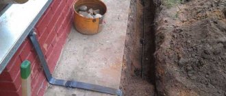
Land preparation. Using the triangle diagram as an example (Fig. 6).
The trench is dug to a depth of 50-80 cm. The sides of the triangle are 1.0-1.5 m long.
Metal rods are driven in. To make them easier to penetrate into the ground, it is recommended to sharpen them (Fig. 7);
then connecting plates are welded to the tops of the rods (Fig. 8),
connecting the conductor to the plate through a bolt (Fig. 9), and at the very end we fill the grounding structure with earth.
At the end, it is necessary to measure the grounding and check the resistance of the entire circuit.
Types of ground loops
The soil can accept any amount of electricity. However, for the system to operate effectively, it is necessary to choose the optimal contour shape. The most common are triangular and linear designs. The first type arose earlier, but now many are switching to the second option.
Triangle
3 electrodes are used to drain current. They are connected by metal strips forming an isosceles triangle. To properly ground a house using this method, geometric proportions must be observed. When installing, take into account the following recommendations:
- you need to prepare 3 pins and strips;
- the electrodes should become the corners of the figure;
- the use of strips and pins of the same length is required;
- the structure must be buried at least 0.5 m.