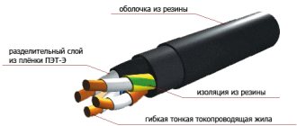
Cable lines (CL) of high and low voltage often have to be laid in difficult conditions. Cables are laid in trenches in the ground, in cable ducts, on trays along open overpasses or along building structures inside industrial premises. In these and other cases, cables that have an outer metal sheath, called armor, are often used. Steel armor serves as protection against mechanical damage. It can be made in the form of twisted metal strips or a braid of galvanized wire wound around the cable body.
Grounding of armored cable indoors
Installation of this type of cable, and therefore grounding, is strictly prohibited where there is an outer cover that can be ignited. Laying can only be carried out in those building structures where the route and connection points will be available at any time for visual inspection and the opportunity to make repairs.
If installation is carried out on wet concrete or on a wooden surface without plaster, care should be taken in advance to place a special bracket that will ensure a distance of at least 5 centimeters between the cable and the surface. Also, in such cases, many resort to the use of metal pipes or gutters, which will serve as a separator between the surface and the cable itself.
If the owner of the premises needs to insert the cable inside, this can be done in two ways, through:
- foundation;
- wall opening.
In order not to damage the cable when pulling, it is necessary to install a plastic or metal pipe at the entry point, the internal diameter of which will be approximately twice the diameter of the cable itself. This will allow them to be easily pulled into the room, and also eliminate the possibility of damage.
It is extremely important to ground the cable, both from the side of the shield and the support. It is also necessary to take into account the fact that there should be no connections from the input point to the support
Reasons for the popularity of wire trays
First of all, these trays are more affordable. The advantages of these structures also include the low cost of their installation. Without touching on the material component, the advantage of this type of tray is also its high level of electromagnetic compatibility. Another definite plus is the provision of high-quality cable cooling. Other reasons for the relevance of wire trays include:
- no need to use additional expensive accessories;
- no dust on the surface of the trays;
- high level of load capacity.
Laying armored cables in the ground
Laying cables in armor in different types of soil has its own characteristics. In places with unstable soils, in rocky formations and in permafrost areas, a cable with wire armor is laid, and in places with a stable type of soil - with tape armor. When laying, it is necessary to ensure that the protective sheath does not have electrical breaks along its entire length. The armor is grounded using a flat, uninsulated wire. The required cross-section of the grounding wire is given in the table:
How to ground cable armor
For installation in difficult conditions and to protect the electrical line from damage, armored cables are used, representatives of which are VBBbShv and AVBbShv. Armored is an electrical cable protected by a layer of metal tapes or layers of metal wire. Definitions of names and types of cable products and related terms are described in GOST 15845-80. A prerequisite for its use is the grounding of the armor, since current standards and requirements indicate the need to ground all conductive parts of the electrical installation. In this article we will look at how to ground an armored cable.
Grounding trays using PUE - All about electricity
In order to commission cable routes, it is necessary to take various measures to improve the safety of the equipment. One of these measures is the grounding of cable trays. This process must be given special attention in order to do everything correctly and in accordance with GOST standards. It should also be noted that cable trays come in many different types, so the connection method is different.
They can be wire, sheet, perforated and all-metal. We will talk about how to ground each of the design options below.
1.7.85
Protective electrical separation of circuits should generally be applied to one circuit.
The maximum operating voltage of the separated circuit should not exceed 500 V.
The power supply for the separated circuit must be supplied from an isolation transformer that complies with GOST 30030 “Isolation transformers and safety isolation transformers”, or from another source that provides an equivalent degree of safety.
Current-carrying parts of the circuit powered by an isolating transformer must not have connections with grounded parts and protective conductors of other circuits.
It is recommended to lay conductors of circuits powered by an isolation transformer separately from other circuits. If this is not possible, then for such circuits it is necessary to use cables without a metal sheath, armor, screen or insulated wires laid in insulating pipes, boxes and channels, provided that the rated voltage of these cables and wires corresponds to the highest voltage of the jointly laid circuits, and each circuit protected from overcurrent.
If only one electrical receiver is powered from an isolation transformer, then its exposed conductive parts should not be connected either to the protective conductor or to the exposed conductive parts of other circuits.
It is allowed to power several electrical receivers from one isolation transformer if the following conditions are simultaneously met:
1) open conductive parts of the separated circuit must not have an electrical connection with the metal body of the power source;
2) open conductive parts of the separated circuit must be connected to each other by insulated ungrounded conductors of a local potential equalization system that does not have connections with protective conductors and open conductive parts of other circuits;
3) all socket outlets must have a protective contact connected to a local ungrounded potential equalization system;
4) all flexible cables, with the exception of those supplying equipment of class II, must have a protective conductor used as a potential equalization conductor;
5) the shutdown time of the protection device in the event of a two-phase short circuit to open conductive parts should not exceed the time specified in Table 1.7.2.
Electrical Safety Protective Measures
If you strictly follow all the rules during operation, the use of electrical appliances does not pose any danger. Protection against electric shock is achieved in the following ways:
- the part of the electrical circuit through which the current passes must not be accessible to accidental touch;
- live parts that are open must not contain voltage dangerous to human life, even if the insulation is broken;
- such inaccessibility is achieved through protective shutdown, the use of low voltage, double insulation, equalization and potential equalization, the implementation of barriers, and the location of electrical equipment outside the accessibility zone.
The use of measures in combination to protect against electric shock should not reduce the effectiveness of each.
If the electrical equipment is located in the potential equalization area, and the highest operating voltage is no higher than 25V AC and no more than 60V DC, then there is no need for protection against direct contact.
Also, the protective functions of electrical equipment must be provided during the manufacture of the latter, or during installation.
How to ground the armor of a cable laid in a cable structure
Cable structures are structures designed for laying cables and any equipment that ensures the normal operation of cable lines. These include boxes, channels, tunnels, overpasses, galleries and double floors. The laying of armored cables inside cable structures must comply with the requirements set out in PTEEP and PUE. Both the cable armor itself and the conductive parts of cable structures must be grounded. It is allowed to ground the armor tape to metal boxes or channels. Load-bearing metal structures of buildings and structures can be used as a grounding loop.
A large selection is presented on the website. After reading the product description, you can make a choice yourself or contact a company specialist who will competently advise you on issues of price and quality.
If we are talking about an armored cable, it is necessary not only to ground the core, but also to ground the armor. This procedure is necessary to eliminate stray currents. Like any action that is performed in relation to cable and wire products, cable grounding must be performed correctly. It is necessary that grounding occurs at all points of the circuit. To do this, the grounding procedure is performed on both sides of the connection to the panel or equipment. You also need to know the nuances that will allow you to ground the armor efficiently. One of these nuances is the presence of a cable route along which there are coupling connections. What to do in this case? In order for the grounding to be carried out correctly, it is necessary to make jumpers from copper wire in front of the coupling.
There are many additional nuances that need to be taken into account. Specialists with decent work experience know about the specifics of grounding cable armor. They will do the job efficiently and accurately. If an amateur takes on the job, grounding may be done incorrectly, and this will lead to incorrect use of the cable.
Cooperation with Cablestar
If you need it, just call our company and place an order. We have a large selection of high-quality cable and wire products. In stock you can find VVGngLS cables, (including) and other brands of wires. If you need detailed professional advice, the company’s specialists are ready to provide it. Contact us by phone or leave requests on the website, online, and consultants will help you choose the appropriate cable, as well as place your order. We always focus on the needs and preferences of our clients.
In our company, favorable terms of cooperation await you. We offer all customers the best prices and guarantee full compliance of cable and wire products with all declared properties and characteristics.
the site responds
2.3.71. Cables with metal sheaths or armor, as well as cable structures on which cables are laid, must be grounded or neutralized in accordance with the requirements given in Chapter. 1.7.
2.3.72. When grounding or neutralizing the metal sheaths of power cables, the sheath and armor must be connected by a flexible copper wire to each other and to the housings of the couplings (end, connecting, etc.). On cables of 6 kV and above with aluminum sheaths, grounding of the sheath and armor must be carried out with separate conductors. It is not required to use grounding or neutral protective conductors with a conductivity greater than the conductivity of the cable sheaths, however, the cross-section in all cases must be at least 6 mm 2. The cross-sections of grounding conductors of control cables should be selected in accordance with the requirements of 1.7.76-1.7.78. If an external end coupling and a set of arresters are installed on the structure support, then the armor, metal shell and coupling must be connected to the grounding device of the arresters. In this case, using only metallic cable sheaths as a grounding device is not allowed. Overpasses and galleries must be equipped with lightning protection in accordance with RD 34.21.122-87 “Instructions for the installation of lightning protection of buildings and structures” by the USSR Ministry of Energy.
2.3.73. On oil-filled low-pressure cable lines, the end, connecting and locking couplings are grounded. On cables with aluminum sheaths, feeders must be connected to the lines through insulating inserts, and the housings of the end couplings must be insulated from the aluminum sheaths of the cables. This requirement does not apply to cable lines with direct input into transformers. When using armored cables for low-pressure oil-filled cable lines in each well, the cable armor on both sides of the coupling must be welded and grounded.
2.3.74. The steel pipeline of oil-filled high-pressure cable lines laid in the ground must be grounded in all wells and at the ends, and those laid in cable structures - at the ends and at intermediate points determined by calculations in the project. If it is necessary to actively protect a steel pipeline from corrosion, its grounding is carried out in accordance with the requirements of this protection, and it must be possible to control the electrical resistance of the anti-corrosion coating.
2.3.75. When a cable line transitions into an overhead line (OHL) and if there is no grounding device at the overhead line support, cable couplings (mast) can be grounded by attaching the metal sheath of the cable, if the cable coupling at the other end of the cable is connected to a grounding device or the grounding resistance of the cable sheath complies with the requirements of Chapter. 1.7.
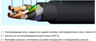
An electric cable with a protective cover of metal tapes or one or more layers of metal wires is called armored (GOST 15845-80). This is a fairly effective way to protect conductors from mechanical damage and from destruction under the influence of temperature, moisture and ultraviolet radiation. In order for the equipment to serve for a long time and trouble-free, the laying of armored cables must be carried out in accordance with all the rules. The requirements for carrying out such work are set out in the “Rules for the technical operation of power plants and networks of the Russian Federation”, approved by the Ministry of Energy of the Russian Federation on June 19, 2003 and mandatory for execution throughout the Russian Federation.
Grounding an armored cable is a necessary condition for safe operation and maintenance of the cable line. Current regulatory documents require that all conductive parts of conductors be grounded.
Impact propagation mechanisms
Redistribution of energy in high voltage networks occurs during switching. Instant changes in the parameters of the electrical main are recorded. In this case, electromagnetic fields arise that penetrate the secondary circuits. The consequence is an impact on the equipment, the insulation of the connecting cable, and distortion of the transmitted signals.
The electromagnetic field generated during the transient process propagates and penetrates the secondary circuits. Together, these phases form a single physically indivisible process. Attempts to reduce the noted processes to simplified models lead to incorrect decisions.
The indivisible electromagnetic field is considered as a single one. It contains 2 elements – electric and magnetic. The synthesis of the final results is carried out based on the principle of superposition. The overlap of processes leads to interference in constructive and destructive forms.
The voltage that is generated during the transient process penetrates the secondary circuits with a set attenuation coefficient. The level of overvoltages during switching in 110 kV networks can exceed the nominal value by more than three times. This figure increases to 300 kV. For typical substations, the attenuation coefficient is assumed to be 100 kV. Then the potential that arises during switching on the secondary circuits will be 3 kV.
Voltage is induced in the secondary circuits due to the high-frequency transient current and magnetic field flux. For typical substations, the value of mutual inductance is approximately 1 μH. If we assume that a current of 500 A flows through the high-voltage buses, having a frequency of 1 MHz, then the overvoltage on the secondary cable is 3141 V.
The above calculations convince us that there is a real danger of a destructive effect on equipment and devices. Reducing electromagnetic influence can be achieved by shielding cables. Thanks to the protection of cable shields, it is possible to significantly reduce the magnitude of overvoltages. It has been experimentally confirmed that the level of overvoltages in circuits with a shielded cable that has been grounded is reduced with even greater efficiency.
Wire trays
Advantages of wire trays
If we compare this version with other products, wire trays have quite a lot of positive features, here are some of them:
- installation is not too expensive;
- the products themselves are much cheaper than sheet products, as well as ladder types;
- wire cooling is much better than in designs with closed boxes;
- in order to ground the tray, you can use a fairly simple circuit;
- Very little dust accumulates inside, several times less than in galvanized or metal structures;
- in terms of load indicators, cable trays made of wire are not inferior to others, for example, sheet trays;
- There is no need to buy expensive additional accessories to use it.
It will take very little effort to ground the cable tray, because it initially has excellent electromagnetic compatibility. Products made from polyvinyl chloride are not able to provide high-quality interference suppression. Because of this phenomenon, metal cable trays produced by the DKS company began to be widely used by cellular operators.
According to the PUE, it is mandatory to ground all trays. The conductive supporting structure for the wires requires complete, comprehensive protection. And the work itself is carried out in full compliance with the standards that are in SNiP. For example, DKS brand trays are grounded at least at two points - at the beginning and the end.
Wire channels for laying cables are conductive and therefore need to be connected to a potential equalization system. Unlike the connections found in tape and sheet channels, wire trays have less contact and therefore less conductivity. For this reason, a special terminal is used, which ensures the required resistance value between the cable system and the ground bus.
Nature and nature of interference
The frequency range of interference, its magnitude varies over a fairly wide range. Static electricity discharges amount to milliamps. And lightning strikes cause hundreds of kiloamps. To this are added industrial frequencies at short circuit currents (SCC). Their rapid growth under the influence of lightning or radio transmitting devices reaches several gigahertz. Such conditions create a very harsh electromagnetic environment (EME).
Electromagnetic interference affects various objects. The nature of dissemination and influence manifests itself in several ways. The impact is carried out on the body of a particular equipment through radiation. Through analog or digital interfaces and grounding ports, interference can enter the devices.
Often microprocessor equipment is surrounded by open switchgear (OSD), power buses and apparatus. In such places, the amount and magnitude of interference increases significantly. The main source of impact is switching in power networks, affecting secondary circuits.
The nature of the connections between secondary circuits and high-voltage systems is determined by their mutual location. The design of highways with secondary circuits must take into account geometric relationships. However, everyday practice leads to many cases of violation of this condition. This happens due to contradictions with other regulatory requirements.
In many of these situations, circuit shielding provides protection against interference. But such an operation is not able to solve all the problems of neutralizing the negative impact. For more reliable protection, you cannot do without grounding the screens. They are designed to reliably separate the conductors of one electrical circuit from the effects of other circuits and electromagnetic atmospheric phenomena.
Grounding systems (GS)
According to the main provisions of the PUE, the grounding of electrical installations and working equipment can be organized in several ways, depending on the neutral connection circuit at the transformer substation.
Based on this feature, there are several types of grounding systems, designated in accordance with generally accepted rules. Their classification is based on a combination of the Latin symbols “T” and “N”, which means the transformer neutral grounded at the substation.
The letters “S” and “C” added to this designation are abbreviations from the English words “common” - common gasket and “select” - separate. They indicate the method of organizing the grounding conductor along the entire length of the supply line from the substation to the consumer (in the first case - a combined PEN, and in the second - separate PE and N).
Combined with a hyphen “CS” means that on some part of the route the grounding conductor is combined with the working “zero”, and on the remaining section they are laid separately.
Grounding armored cables indoors
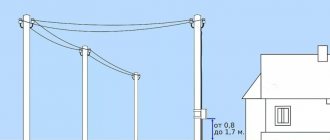
Armored cable 0.4 kV can be laid over any metal structures if they are grounded and also accessible for maintenance. Laying on wet concrete and wooden surfaces is prohibited. In this case, you need to provide a gap of at least 5 cm between the line and the surface; for this you can use various brackets or lay the line in metal pipes and gutters.
An armored cable can be inserted into a building through the foundation and walls. In order to eliminate the possibility of damage, a metal or plastic pipe with a diameter 2 times larger than its outer diameter must be laid at the cable entry, or at the point of transition through a wall or foundation.
The next step is that the armor needs to be grounded in the shield and at the side of the support from which it comes. Also, as described above, there should be no connections in this area (support-shield). At the input to the shield, the cable is divided into cores, which are connected to switching devices (switch or automatic circuit breakers), and its armor is connected to the shield body. That, in turn, must be grounded.
In cable structures (trays, galleries, overpasses, under floors), it is permissible to ground the armor by ensuring contact with metal boxes, channels or other grounded structures.
To organize an electrical network in a private house, it is connected to the power line using an overhead or underground connection. In the case of laying cables underground, VbBShv is often used; its armor, as in the cases described above, must be grounded on both sides.
The screen of control cables or optical cables must be grounded on at least one side. This is done to reduce or completely eliminate the influence of electromagnetic fields on the information line.
However, this task is better handled by double-sided grounding. The screen is connected to the main shield using a flexible conductor with a cross-section of at least 4 square meters. mm.
Types of material (profiles)
According to the requirements of the PUE, which contain instructions on what the resistance of current flow in the ground should be, in most cases this indicator is set at a level of no more than 4 ohms. To obtain this value, you usually have to make a lot of effort to adhere to the same technology requirements.
First of all, this concerns the materials used in assembling the grounding loop, selected based on the following conditions:
- When choosing pins, preference should be given to ferrous metal blanks;
- The most commonly used rod is a standard size of 16-20 mm or a corner with parameters 50x50x5 mm and a metal thickness of about 5 mm;
- It is not allowed to use reinforcement as circuit elements, since it has a hardened surface that affects the normal flow of current;
- For these purposes, it is pure rod that is suitable, and not its reinforcement substitute.
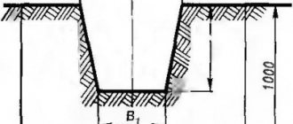
Note! For areas with dry summers, thick-walled metal pipes are best suited, the lower end of which is flattened into a cone, and then several holes are drilled in this part of the pipe. According to the provisions of the PUE, before placing them in the ground, holes of the required length are first drilled, since driving them manually is quite problematic
In the case of a particularly dry summer and a sharp deterioration in the parameters of the ground electrode, a concentrated saline solution is poured into the hollow parts of the pipes, which makes it possible to obtain the resistance that should be in accordance with the requirements of the PUE. The length of pipe blanks is selected within 2.5-3 meters, which is quite enough for most Russian regions
According to the provisions of the PUE, before placing them in the ground, holes of the required length are first drilled, since driving them in manually is quite problematic. In the case of a particularly dry summer and a sharp deterioration in the parameters of the ground electrode, a concentrated saline solution is poured into the hollow parts of the pipes, which makes it possible to obtain the resistance that should be in accordance with the requirements of the PUE. The length of pipe blanks is selected within 2.5-3 meters, which is quite enough for most Russian regions.
This type of profile blanks has special requirements regarding the order of their placement in the soil and consists of the following:
- Firstly, the pipe elements of the protective circuit must be placed at a depth exceeding the soil freezing level by at least 80-100 cm;
- Secondly, in particularly dry areas, approximately a third of the length of the ground electrode should reach wet soil layers;
- Thirdly, when fulfilling the second condition, one should focus on the peculiarities of the location of the so-called “groundwater” in a given region. If they are located at a significant depth, according to the rule formulated in the provisions of the PUE, it will be necessary to prepare longer pipe sections.
The type and profile of the pin blanks used in the construction of the grounding switch can be found in the figure below.
Acceptable pin profiles
In practice, in most regions of Russia, a steel corner and a strip of the same metal are usually used. In order to obtain more accurate parameters of the grounding elements used, geological survey data will be required. If this information is available, it will be possible to involve specialists in calculating the parameters of the ground electrode.
What is metal bonding made of?
The elements connecting the pins (metal bond) are usually made of the following electrical materials:
- A typical copper busbar with a cross-section of less than 10 mm2;
- Aluminum strip with a cross section of about 16 mm2;
- Steel strip 100 mm2 (standard size – 25x5 mm).
Classic metal ties are usually made in the form of steel strips cut to size and welded to the corners or heads of the rod.
Important! The quality of the welding joint determines whether this grounding device or circuit can pass verification tests for compliance of the contact resistance with the standardized value (4 Ohms)
When using more expensive aluminum (copper) strips, a bolt of a suitable size is attached to them for welding, on which the supply busbars are subsequently fixed
The main thing you need to pay attention to when arranging any connections is the reliability of the resulting contact
To do this, before preparing the bolted joint, it is necessary to thoroughly clean both parts to be connected until the shine of clean metal appears. Additionally, it is advisable to sand these places, and after tightening the bolt, tighten it well, which will ensure more reliable contact.
Shielded control cable
The world of modern communications requires the installation of many wiring systems. Therefore, nearby (in the same channel, gutter or well) there are cables for various purposes. The electromagnetic fields existing in each conductor influence each other. To neutralize the resulting interference, a shielded cable is used.
The screen is needed to protect the internal electromagnetic field from external influences and to minimize the internal influence on currents and fields of other conductors. The appearance of electromagnetic potentials on the surface of the cable product is removed by grounding the screen.
Among the many shielded products, control cables have a special purpose. They serve for the exchange and transmission of data in conditions of limited access. The control cable provides reliable communication with devices to receive the necessary signals and messages. The product is sometimes referred to as "multi-core control cable".
The shield in control cables is designed to protect information, the transmission of which is complicated by the influence of electromagnetic fields from external sources. The screen is made from thin foil or copper wire. The shielding coating is also made of tinned wire braid. There are combinations of an electrostatic screen made of tinned drainage wire with a metallized film.
Design features of control cables, types of screens
The basis of the structure is current-carrying conductors. They are made mainly from copper. Insulation of conductive rods is carried out using PVC materials.
The cores are twisted in pairs using the optimal pitch. Pairs can also be twisted along their length while maintaining the optimal pitch. Thanks to pair twisting, crosstalk is effectively suppressed.
The structure of the control cable contains a filler, a screen, and an outer sheath. To fill the gaps between the cores, special materials are used to give the cable a rounded shape. Some control cables are armored.
The control cable shield ground is located directly under the outer sheath. Its usual place is the top layer of the layer. The screen has the form of a winding consisting of copper (aluminum) tape or foil. The continuity of the screen is ensured by the overlap of the protective layers. It is only required to maintain the permissible bending radii.
It is allowed to produce screens whose design is distinguished by longitudinally applied corrugated aluminum tapes with overlap. Some types of shielding are made using aluminum foil, along which copper wire is located longitudinally.
The outer shell is made of various PVC materials. Many of them are flame retardant and self-extinguishing. The outer sheath makes the control cables resistant to chemicals and oils.
Application areas for shielded control cables
Screened control cables are divided into 2 main types according to their intended purpose:
- for fixed installation, grades KVVGE and AKVVGE are used;
- For non-stationary laying, the KGVEV brand is used.
The letter "E" becomes common when labeling varieties. It indicates the presence of a screen. Screened control cables are used for the purpose of connection between electrical devices and electrical distribution devices. The possibility of laying in groups is provided.
The range of applications is significantly expanded when flexible control cables are used. They are used in conducting and organizing:
- electrical installation work;
- automated control systems (in production facilities of various levels of complexity);
- air conditioning and heating technology;
- transportation and automation systems;
- power plant equipment;
- security systems;
- alternative energy;
- control of machines and devices.
Flexible control cables are effectively used in moving circuits. Certain types of control cables can be used outdoors because the conductors are resistant to ultraviolet radiation.
The range of control cables includes products designed for intrinsically safe installations. Some varieties are resistant to abrasion, mechanical stress, and aggressive chemicals.
Signal Wire Shielding Methods
The signal wire (cable) is used to connect various elements (components) of the system. Most often, the signal wire contains several pairs of conductive wires with polyethylene insulation, as well as with a PVC sheath. Some types of signal wires have a special shield to protect against electromagnetic interference and are called “shielded signal cables.”
Shielding Signal Wires
Shielding is the protection of a signal wire from noise or unwanted signals.
Signal wires have high quality signal transmission due to their shielding and twisted pair construction to ensure better matching of their longitudinal impedance and ground impedance. At high frequencies, common-mode interference can occur due to the difference between the length of the wires and the frequency characteristics of their impedances.
Signal wire shielding methods take into account the path of interference.
To completely eliminate the adverse effects of parasitic capacitive coupling, an electrostatic screen made in the form of a conductive tube is used. In this case, it is correct to ground the electrostatic shield only from the side of the signal source. In Fig. Figure 1 shows how to improperly ground an electrostatic shield.
In Fig. Figure 2 shows hybrid grounding, which is the most popular method when transmitting a broadband signal from a distant source with high resistance.
Making a screen that will reliably protect against parasitic inductive couplings is much more difficult than a classic electrostatic screen. For manufacturing, you need a material with increased magnetic permeability. In addition, the thickness of such a screen should significantly exceed the thickness of electrostatic screens.
For frequencies less than 100 kHz, it is possible to use steel screens or screens made of permalloy (an alloy of iron and nickel). For higher frequencies, screens made of copper or aluminum are suitable.
Since shielding the magnetic component of interference is difficult, special attention must be paid to reducing the inductance of the signal cable and selecting suitable receiver and transmitter circuitry. In Fig. 3, 4, 5 and 6 show connection diagrams for the amplifier and screen, providing different rms noise amplitudes.
For most, for example, temperature sensors, the signal sources do not have a protective ground, and therefore an electrostatic shield is used along with a differential amplifier and output resistors. The screen grounding diagram in this case is shown in Fig. 3.
Double shielding of long cable
A double shield (Fig. 7) is used to improve the quality of shielding over a wide frequency spectrum. The internal screen is grounded on one side (the signal source) to prevent the passage of capacitive interference, while the second, external screen, is used to reduce high-frequency interference.
In any case, to prevent accidental contact of the screen with metal objects and the ground, it must be insulated.
In the case of a long cable, even with proper grounding, interference still passes through the screen, and therefore it is better to transmit the signal over a significant distance or with serious requirements for measurement accuracy either in digital form or via a fiber-optic cable. For this purpose, analog input modules with a digital RS-485 interface or fiber-optic converters of the RS-485 interface can be used.
Galvanic isolation
The above problems can be radically solved using galvanic isolation (Fig. with separate grounding of the digital, analog and power parts of the system. That is, the signal between electrical circuits is transmitted without contact between them.
Requirements for conductors
When installing grounding, as well as protective grounding, steel cable sheaths of any class or armor are connected to the charger through copper conductors of a standardized cross-section. This requirement also applies to coupling or end coupling housings. On lines designed to transmit high-voltage power (6 kV and above) and having an aluminum sheath, coupling grounding is performed with separate conductors.
For this purpose, it is prohibited to use copper conductors with a conductivity greater than the corresponding indicator for cable sheaths.
The general requirements of current standards provide for the use of bare copper conductors with a cross-section of at least 6 mm square. The same parameters for control cables are specifically stipulated in the PUE (see clauses 1.7.76-1.7.78).
If the support of the air supply to the electrical installation is equipped with end couplings containing arresters, their housings are connected directly to the protective device charger. The use of cable sheaths alone in this capacity is not allowed in this situation. Special overpasses and galleries used to accommodate explosive cables must be equipped with protection against lightning discharges and lightning.
When moving from an underground laying line to a section of its overhead wiring and if the reinforced concrete support does not have its own charger, the couplings are allowed to be grounded to the cable armor. This approach is permissible only if the repair or extension coupling at the other end is connected to the station grounding circuit, or if the resistance value of the sheath of the grounded cable is sufficiently small.
For mobile equipment
There are other systems for organizing protective grounding of equipment (TT and IT, for example), which use a neutral conductor as a “zero” conductor and involve the arrangement of a re-charger on the consumer side.
In the first case, the neutral at the substation is solidly grounded, and in the second, it is not connected anywhere at all. These options for switching on the neutral are rarely used and only in cases where it is necessary to re-ground mobile electrical installations (provided that this is very difficult to do on the generator side).
According to GOST 16556-81, the IT system discussed above is used for mobile electrical equipment, during the implementation of which re-grounding is organized on the consumer side. This standard specifies the technical characteristics and parameters of the storage facility, which is temporarily installed in the area of upcoming work.
Grounding conductors for cable armor in the ground
The laying of main power supply lines in the ground depends on the properties and composition of the soil layer being opened.
The table shows the ratio of the cross-sections of the cable cores (top line) and the ground electrode (mm²):
| <10 | 16―35 | 50, 70, 95, 120 | 150―240 |
| 6 | 10 | 16 | 25 |
If you need to connect a private house to the power grid, then CEL can be laid not only in the ground, but also through the air. In each of these cases, protection of the highway is required on both sides. When constructing it, the following rules are adhered to:
- Contact at the point where the grounding wire is connected to the armored cable is ensured by using a special clamp (clip), bolts or soldering. In the latter case, the contact planes are first cleaned and tinned. Attach the protection to the upper steel strip, and in the case of wire armor - to all wire rods around the circumference.
- The outer shell of KEL prevents damage along the entire length of the pipeline. If it is necessary to carry out repairs or when connecting sections for splicing, use a special coupling. To complete the circuit, it is attached to the armor on each side with stranded copper wire. The adapter kit includes waterproofing and connecting elements: grounding conductor, lugs with shear screws and clamps.
- The ends of the armored cable are cut carefully, taking care not to damage the protective sheath. The upper braid is removed to a greater length than the inner one. To prepare the connection without errors, use a special template, which is offered by cable manufacturers.
To ensure the safety of the grounding loop, there should be no roots of trees and shrubs in the places where the cable lines are laid. When the highway crosses high-risk communications (roads and construction sites), additional safety measures are taken. To do this, sand bedding is used and cable channels are installed. In such cases, braiding is preferable to wire braiding. In addition, there are options for laying CEL indoors and on various structures.
Recommendations
The grounding conductor is connected to the armor using soldering, and if the coupling is sealed, then with bolts or a clamp (clamp).
To ensure high-quality solder contact, the soldering points are first cleaned and tinned with solder, for example POSSu 30-0.5.
Next, using a wire bandage, fix the grounding conductor on the tinned area and solder it. Solder fat is used as a flux.
For solderless connections, clamps or constant pressure springs are used, which ensure reliable electrical contact around the protective layer.
For tape armor, the grounding is connected to the strips, and for wire armor, the grounding is connected around the circumference to all the wires. When connecting the ends of building lengths, sealed couplings are used; their kit includes:
- waterproofing elements;
- connecting elements (for example, tips with shear bolts);
- grounding wire, it connects the armor of both connected ends;
- clamps for connecting wires to tapes or wire armor.
To properly cut the cable, the top layer of insulation is removed to a greater length than the bottom layers. In this way, the conductors are separated and a section is formed on the surface of the armor for the ground connection. Depending on the coupling, the manufacturer may provide a template for correct cutting.
Sources
- https://www.elec.ru/articles/kak-chitat-markirovku-kabelya/
- https://shallot.ru/how-to-properly-ground-the-armored-cable-cable-shield-grounding-is-it-necessary-to-conduct-it.html
- https://altyn-stroy.ru/zazemlenie-broni-kabelya-pue/
- https://elektrik-sam.ru/jelektroprovodka/3460-kak-sdelat-zazemlenie-broni-kabelja.html
- https://alekstroy.com/zazemlenie-bronirovannogo-kabelya-pue/
- https://samelectrik.ru/kak-sdelat-zazemlenie-broni-kabelya.html
Is it necessary to ground the cable armor?
For installation in difficult conditions and to protect the electric line from damage, armored cables are used, representatives of which are VBBbShv and AVBbShv.
Armored is an electrical cable protected by a layer of metal tapes or layers of metal wire.
Definitions of names and types of cable products and related terms are described in GOST 15845-80.
A prerequisite for its use is the grounding of the armor, since current standards and requirements indicate the need to ground all conductive parts of the electrical installation. In this article we will look at how to ground an armored cable.
Application area
Armored cables are used for laying lines in tunnels, shafts, and trenches. They are laid in the ground without the use of HDPE pipes or other types of protection. But it is worth noting that such protection is never superfluous. The armor layer protects against ground movements and other harmful factors.
Interesting:
The armor is designed not only to protect against damage from a shovel or other tool, but also to protect against the teeth of rodents.
Laying on the surface is possible, subject to minimal mechanical loads and stresses. Those. it must be secured and the likelihood of stretching and impact must be minimized. In everyday life, such a cable is used to bring electricity into the house, or to connect a garage, summer kitchen, outbuilding, barn and other buildings to electricity. In this case, they are laid again - in the ground.
Installation stages
Installation of wire routes consists of a set of measures. They require a responsible approach. In addition to installation, a number of preparatory tasks should be completed. Next, we will dwell in detail on each of the stages.
Wiring diagram
First, a diagram of the electrical wiring in the room is made. You can create it yourself if you have an understanding of electricity. Otherwise, you will need to use the help of specialists.
Drawing of cable channel passage
The next step will be to make a drawing of the cable trays, taking into account the location of all junction boxes, switches and sockets. To do this, it is better to use a program with the ability to display three-dimensional images.
Wiring diagram for cable channels
Purchasing an electrical box with accessories
Next you need to calculate the required number of accessories. They are necessary for the aesthetic appearance of butt joints. To avoid further problems with installation, you should purchase accessories and cable routes of the same brand.
Marking the cable channel route
According to the previously prepared drawing, the markings for laying electrical trays are transferred to the walls. To maintain horizontal and vertical lines, use a plumb line and level. If you have a laser level, just use it.
Marking walls for electrical wiring
Preparing the cable channel for installation
At this stage, you will need to prepare the appropriate lengths of cable channels. It is recommended to cut as the boxes are installed. It is also necessary to keep in mind that mini cable routes are not equipped with longitudinal connecting accessories. To get a beautiful connection you need:
- Use two boxes, one of them mounted in one piece.
- Cut the second one to the required length along with the protective cover.
- First, the cut-off lid is installed on the solid box, and then the undamaged lid is snapped on.
Fixing the cable channel along the marked route
Fastening the electrical tray to the wall can be done with liquid nails, wood or metal screws, or dowel nails. It is recommended to screw in the fasteners in a staggered pattern. When using liquid nails, glue should be applied to the back of the box in a zigzag pattern.
Attaching the cable channel to the wall
Laying and securing cables in the channel
When laying wires in a cable channel, you will need to adhere to the following rules:
- Power cables must be placed without twisting each other.
- Telephone, computer and television cable lines must be laid separately from power electrical wiring.
- The wires laid in the box are secured with spacers and clamps.
Installation of electrical elements
All that remains is to connect the switches and sockets, securing the devices in the prepared places.
Installation of sockets in a cable channel
Tags: , machine, tag, beat, sconce, view, harm, house, , grounding, measurement, cable, cable, how, computer, design, circuit, , tray, magnet, installation, multimeter, voltage, transfer, connection, rule , wire, wiring, project, laying, start, , work, calculation, relay, repair, row, light, system, resistance, term, circuit, ten, type, current, triangle, , installation, phase, shield, effect