Introduction
The Beatles or the Rowling Stones?
Michael Jordan or LeBron James? Steak, deep or medium rare? Forward or flyback converter? These are just some of the eternal questions that people have been arguing about for many years, vigorously defending their opinions and not finding the only correct answer. But, in truth, in each of these examples, both answer options have their advantages, and therefore, the correct answer may be both. In this article we will focus on forward and flyback converters. We will discuss the characteristics of active clamping forward and continuous conduction mode flyback topologies, demonstrating the advantages and disadvantages of each using two power supplies as examples. In particular, we'll look at 51W PoE (Power over Ethernet) power supplies that comply with the IEEE 802.3bt standard and are designed for telecommunications applications.
The new standard has increased the maximum power to 71 W, making the forward topology more attractive than it was previously, when the maximum power was 25.5 W. At the same time, new transformer core sizes and technologies are emerging, resulting in increased power and efficiency of flyback converters. As a result of these improvements, as well as thanks to the development of power semiconductor switches, it is necessary to take a fresh look at the question: which converter is better: forward or flyback?
An analysis of the operating principles and features of forward and flyback converters is beyond the scope of this article. However, this article's brief overview of each topology helps highlight the similarities and differences, as well as the strengths and weaknesses of both types of converters.
Energy characteristics
If we look at the schematic diagram of the device, we can see that there are decreases and increases in a linear relationship. It is the quality and duration of the pulses that determine the characteristics of the output voltage. Modulation is carried out for the feedback circuits. The energy performance of a transformer of this type is individual in each specific case, but limiters are always installed, because the device operates at maximum power.
As a result, the microcircuits stop processing pulses. Interference and noise are created, which have a significant negative impact on the progress of work. Special modulators are used that reduce the energy losses of the pulse transformer.
Forward converter with active limiting
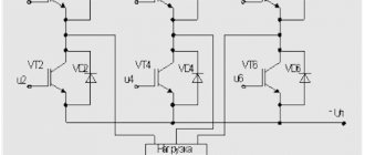
A typical diagram of a forward converter with active limiting is shown in Figure 1. For simplicity, the diagram shows only the power switches, transformer, output filter and controller. Auxiliary components, such as those related to the controller harness, are not shown for clarity.
Rice. 1. Forward converter with active limiting
The controller controls two power MOSFETs QPRI and QCLAMP located on the primary side. The keys are switched alternately at a high frequency (100 kHz). When one power transistor is on, the other must be off. The ratio of the portion of the period during which QPRI is turned on (QCLAMP is turned off) to the full commutation period is called the duty cycle or duty cycle D. The duty cycle determines the density of voltage pulses in the primary winding of the VPRI transformer. Thanks to the magnetic coupling between the windings, these pulses are transmitted to the secondary side of the converter. The voltage on the VSEC secondary winding is scaled according to the transformation ratio (N), determined by the ratio of the number of turns in the windings.
The secondary side voltage is rectified using a synchronous rectifier consisting of QFWD and QFREE power MOSFETs. The rectified voltage is supplied to the output filter formed by the inductance LOUT and the capacitor COUT. This low-pass LC filter is necessary to convert the pulse train into a constant voltage at the output of the power supply. The output voltage is proportional to the duty cycle D and the turn ratio N. Voltage secondary voltage (VSEC) pulses are also often used to drive power MOSFETs that act as rectifier diodes. This circuit is called a synchronous rectification circuit (SR). It provides higher efficiency compared to conventional diodes.
Field of application of flyback transformer
A flyback transformer is used in a number of cases when power is required for various equipment with power ratings of up to 200 W. These include:
- personal or office computers;
- equipment, gadgets and peripherals;
- types of energy-saving lamps or lamp systems;
- chargers for gadgets and equipment.
Flyback transformers are often used in conjunction with other devices. For example, they are used to manufacture structural components of inverter sources of a welding machine.
Flyback topology
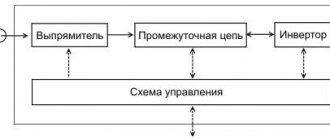
A typical flyback converter circuit is shown in Fig. 2. The controller controls the power MOSFET located on the primary side (QPRI) and the synchronous rectifier MOSFET on the secondary side (QSYNC). The transistors are switched on one by one. As with the forward converter, the QPRI power switch is switched at high frequency and variable duty cycle D. The voltage on the primary side of the VPRI transformer is transferred to the secondary side of the VSEC. Unlike the previously discussed forward circuit, energy accumulation occurs directly in the transformer in the intervals when the QPRI transistor is turned on. Then, when QPRI turns off, QSYNC turns on and the stored energy is transferred to the load.
Rice. 2. Flyback converter with synchronous rectification
Thus, the QSYNC transistor is responsible for rectifying the alternating pulse voltage on the secondary winding. To turn QSYNC on and off, a control signal is required, generated by the controller, which is located on the primary side. An additional low-power transformer is used to galvanically isolate this signal.
The filtering circuit in flyback topology is also different from that used in forward converters. The secondary winding of the transformer acts as the inductance of the output LC filter. The resulting DC voltage VOUT1 at the output of the power supply is proportional to the value of D and the transformation ratio N. In addition to the main LC filter formed by the secondary winding and capacitor COUT1, an optional LC filter containing the inductance LOUT2 and the capacitance COUT2 is often used. This low-pass filter further reduces the level of ripple in VOUT2 at the power supply output.
A little history
Switching power supplies began to develop in parallel with transformer ones from the 40s of the last century. But the production of SMPS stopped because it was expensive, and the sources themselves were complex and cumbersome.
At the end of the 20th century, with the development of transistors and integrated circuits, pulse circuitry was resurrected. In 2022, every inhabitant of the planet uses devices based on pulse circuitry. These are ordinary chargers for phones of all kinds, TVs, computers, LED light bulbs, uninterruptible power supplies... the list goes on and on.
Comparison of converters
Comparison of the number of components and the quality of output filtration
Perhaps the easiest way to compare forward and flyback topologies is by the number of components used. This point is quite important, especially considering the impact it has on the size and cost of the power supply. In Fig. Figure 3 shows a simplified diagram of a traditional flyback converter. The QSYNC transistor used in the circuit in Fig. 2, was replaced by a conventional diode. The optional LC filter has been eliminated.
Rice. 3. Simplified circuit of a traditional flyback converter (with rectifier diodes)
In a similar way, we can obtain a simplified circuit of a traditional forward converter, in which the synchronous rectifier transistors are also replaced with diodes (Fig. 4). As can be seen from Table 1, the flyback converter is the clear winner in terms of the number of components used. For this reason, it is generally accepted that a flyback converter is always simpler and cheaper.
Rice. 4. Simplified circuit of a traditional forward converter (with rectifier diodes)
Table 1. List of components used in forward and flyback converters (in order of decreasing cost)
| Components in descending order of cost | Straightforward | Flyback | ||
| Traditional | Modern | Traditional | Modern | |
| Power transformer | 1 | 1 | 1 | 1 |
| Controller (IC) | 1 | 1 | 1 | 1 |
| Power transistors | 2 | 4 | 2 | 1 |
| Output inductance | 1 | 1 | 1 | 0 |
| Signal transformer | 0 | 0 | 1 | 0 |
| Rectifier diodes | 2 | 0 | 0 | 1 |
| Output Capacitance | 1 | 1 | 2 | 1 |
| Total | 8 | 8 | 8 | 5 |
However, modern forward and flyback power supplies for telecommunications applications often use synchronous rectifier circuits, as shown in Figures 1 and 2, as well as a two-stage output filter in flyback converters. As a result, as can be seen in Table 1, this closes the gap in component count and implementation complexity between the two topologies, making it debatable that a flyback converter is always simpler and cheaper.
The almost universal use of synchronous rectification is due to several main factors:
- constant reduction in the cost of power MOSFETs and controllers that support the synchronous rectification function;
- reducing the output voltage and increasing the output power of modern power supplies.
Obviously, attempting to use a conventional diode rectifier in converters with an output voltage of 3.3 V and a current of 20 A is unlikely to be successful. Rectifying 20 A of current, even with a Schottky diode, will result in a loss of approximately 10 W of power if the forward voltage drop across the diode is 0.5 V. The heat generated by the diodes will be extremely difficult to dissipate, not to mention reducing the efficiency of the power supply. This is in stark contrast to the performance of a MOSFET synchronous rectifier, which can have a resistance of around 2.5 mOhm without problems. In this case, the FET dissipates only about (20 A) 2 x 2.5 mOhm = 1 W. It is much easier to remove 1 W of power released in the form of heat from the power switch. Typically, a large and expensive heatsink will have to be used to cool the diode, while the heat sink provided by a certain size PCB will suffice to cool the MOSFET.
In forward converters, to control the MOSFETs of a synchronous rectifier, in the simplest case, you can connect the leads of the secondary winding to the gates of the transistors, as shown in Fig. 1. This method is often called Self-Driven Synchronous Rectifcation (SDSR). If the voltage on the secondary winding is too high, then additional level shifting or limiting circuitry may be required to prevent the maximum gate voltage of the MOSFETs from exceeding the maximum voltage. Because these circuits are relatively simple and use inexpensive components, they are not included in Table 1.
Unlike forward converters, flyback converters, for some esoteric reason, do not work well with the SDSR self-controlled synchronous rectifier circuit. As a result, as mentioned above, to drive the synchronous rectifier MOSFET located on the secondary side, an additional signal transformer is required to transmit the gate drive signal. Using Coilcraft's new 1500 Vrms LPD8035V series miniature transformers is a painless solution to cost and size concerns.
Another reason to close the component count gap between the two power supply topologies is the addition of a second LC filter in flyback converters. You can often come across the statement that flyback converters are noisier than forward converters due to significant current ripple in the secondary windings. This means that if you use a single stage LC filter in a flyback converter, you will need a much larger inductance and capacitor to get the same level of output voltage ripple as a flyback converter. In practice, several approaches can be used to solve this problem:
- use a power transformer with high inductance;
- use a large output capacitor;
- use a two-stage LC filter.
The first two options are usually more expensive. When using a two-stage LC filter, each component can be selected to optimize a specific circuit parameter (low ripple current, low core loss, etc.). As a result, this approach provides the same level of voltage ripple at a lower size and cost.
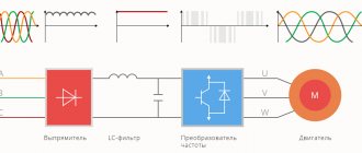
For the reasons stated above, modern forward and flyback converters differ little in the number of components used, dimensions and overall cost, in contrast to traditional forward and flyback power supplies. Table 2 shows the results of a practical comparison of the dimensions and cost of a modern flyback converter (Fig. 5, top) and a modern forward converter (Fig. 5, bottom). Both power supplies have an output voltage of 12V and a power of 51W. They are based on the LT4295 PD controller from Analog Devices. Photos of printed circuit boards are shown in Fig. 5, and simplified circuit diagrams in Figures 1 and 2. As can be seen from Table 2, the flyback converter still remains more compact and less expensive, but the difference is no longer so significant.
Table 2. Comparison of characteristics of real modern converters
| Parameter | Straightforward | Flyback |
| Size (square inches) | 3,2 | 2,6 |
| Cost (relative) | 100% | 90% |
| Efficiency at 4 A | 94,30% | 92,80% |
| Maximum voltage on the power transistor (primary winding) | 90 V | 146 V |
| Maximum voltage on the power transistor (secondary winding) | 85 V | 126 V |
Rice. 5. Examples of forward and flyback converters
Operating principle of the device
The operating principle of the device is based on pulsed energy supply. The equipment is divided into two broad groups: with sigma modulation and pulse modulation. The first differ in that they change the relationship between the duration of the pulses and their frequency. The moment is selected when the energy supply ends and the transistor turns on.
The duration of operation depends on the characteristics of the output voltage. If we talk about options with pulse-width modulation, then the frequency is identical and constant. Voltage is a stable characteristic; it is determined by the duration of the pulse relative to the period of its passage.
Also, the operating principle is determined by whether the magnetic field flow is continuous or intermittent. This is not to say that one of them is better, it just determines the variability of use.
Any single-pass pulse transformer has both advantages and disadvantages. Among the advantages of use are:
- minimal weight and dimensions when compared with other types of equipment designed to operate at frequencies of about 50 Hz;
- protection against short circuit is not needed, since it theoretically cannot occur;
- reducing the use of copper, resulting in the transformer having a minimal price;
- changes in indicators depending on the characteristics of the supply circuit;
- there is no interference, transmission back and forth is excluded due to design features.
But, like any other equipment, a flyback pulse transformer also has disadvantages. These include:
- the maximum energy reserve is 200 W - the indicator is limited by the operation of the throttle;
- there is no possibility of idling, that is, the load must be connected;
- electromagnetic interference occurs and is transmitted, since it is present in the load, and it is needed.
Since the disadvantages are not so significant when compared with the advantages, transformers of this type are popular.
Efficiency comparison
Another common belief is that forward power supplies are much more efficient than flyback power supplies. Previously, such a statement was completely justified. This was explained quite simply by the fact that forward converters have twice the number of FETs, diodes and magnetic components (transformers and inductors), as can be seen in Figures 3 and 4. With twice the number of elements, it is easier to optimize each individual component and distribute the power dissipation evenly .
For example, the flyback transformer performs two functions: it provides galvanic isolation and acts as the inductance of the LC filter. While in forward power supplies different components are responsible for this: a transformer provides galvanic isolation, and a separate inductance is used in the LC filter. This allows the selection of inductors with lower resistance and a transformer with a smaller core size, which leads to a reduction in losses.
Another example of getting the added benefit of using twice the number of components is the use of power transistors. As can be seen from Figures 3 and 4, a forward converter uses two MOSFETs on the primary side, while a flyback converter uses only one. In the same way, the rectifier of a forward converter contains two diodes, while in a flyback converter there is only one. This puts the flyback converter at a disadvantage because the current on its primary side is switched by a single MOSFET, while the current rectification on the secondary side is provided by a single diode. In the past, power supply designers have had to use expensive, bulky, and inefficient power components. This led to high power dissipation, increased heat dissipation and, consequently, a decrease in the efficiency of the power supply.
The use of modern technologies and components has significantly reduced the efficiency gap between the two topologies. For example, the use of a synchronous rectification circuit with modern field-effect transistors has led to a significant reduction in the contribution of rectifier losses to the total power supply losses. Thanks to the long process of development and improvement of MOSFETs, the power switches on the primary side of the converters also contribute less and less to the overall level of losses. The increasing variety of core shapes and sizes, as well as available materials, has led to the availability of compact, efficient, and cost-effective flyback transformers. An example of the new cores being used are Coilcraft transformers, specifically the POE51Q-12E series for flyback converters and the FCT1-120Q3SE series for forward converters, which are IEEE 802.3bt compliant. The result of all of the above is a slight 1.5% gap in the efficiency level between the converters, a comparison of which is given in Table 2. Graphs of the efficiency versus load current for these converters are shown in Fig. 6.
Rice. 6. Dependence of efficiency on load current
How to calculate a single-ended flyback power supply transformer
Independent calculation is required. It is done according to a certain algorithm. The process begins with determining the minimum and maximum current values, then the capacitance of the capacitor and transformers is calculated. Structural components and diodes are selected separately, and at the very end the efficiency of the transformer is calculated.
Determination of the maximum and minimum values of rectified mains voltage
There are formulas for the max rectified network U: the square root of two multiplied by the U of the maximum value of the network. The indicator is equal to 226 for this case. Minimum is the square root of two times U of the minimum voltage value minus 2 times U of the forward voltage drop.
Selection of rectifier diodes
The calculation of the inverse indicator is elementary - it is equal to the maximum, which is stated above, namely - 226 V. The standard circuit is U n * I n / 2 U input min. *n,
where U n is the average load voltage, I n is the load current, and n is the converter coefficient (taken equal to about 0.9).
Standard indicators for case I ex. max = 10 A; U REV. MAX = 560 V.
Capacitor capacitance calculation
The capacitance of the capacitor is calculated by the formula: 0.5* U n* I n/n* U network min.*f network*m* U, f network represents frequencies of 400 Gy, where m is the half-cycle for transit of the U indicator.
Calculation of maximum fill factor
The maximum of this indicator is calculated as a fraction, in the upper part of which there is the value of the additional voltage (which was formed in the closed state after transferring energy to the load), in the lower part the sum of the supplementary voltage with the difference between the input U min and that falling on the transformer transistor.
Voltage surges on the primary side power transistor
In terms of the level of voltage surges on the power switch, the advantage is on the side of forward converters with active limitation. This is a consequence of several factors, but is primarily determined by a more effective fight against the influence of transformer leakage inductance.
Leakage inductance results from incomplete magnetic coupling between the primary and secondary windings, causing not all of the magnetic flux to pass through both windings. Large transformers are usually characterized by increased magnetic flux leakage. Since, for the same output power, the dimensions of the transformers of flyback converters are usually larger than those of forward power supplies, this leads to a higher leakage inductance.
Rice. 7. Leakage inductance in a flyback converter
In equivalent equivalent circuits, leakage inductance is usually represented as a separate inductance (LLKG) that is connected in series with the primary winding, as shown in Fig. 7. When the power MOSFET on the primary side is turned off, the current flowing in LLKG cannot change abruptly. It begins to flow through the relatively small parasitic drain capacitance of the transistor (CPARASITIC), which causes the parasitic LC circuit to oscillate with a rapid voltage jump (Figure 8). This voltage surge is applied to the drain and can exceed the drain-to-source voltage rating of the power switch.
Rice. 8. Voltage surge in flyback converter
The active limiting forward converter combats the problem of switching voltage surges in a special way. For this, an additional circuit formed by a capacitor CCLAMP and a MOSFET transistor QCLAMP is used, as shown in Fig. 1. When the main power transistor of the primary side of the QPRI is turned off, the leakage inductance current is redirected to the CCLAMP by the QCLAMP. The capacitance of the CCLAMP is significantly higher than the parasitic capacitance of the main QPRI power transistor. With the correct choice of CCLAMP and timely switching on of the QCLAMP transistor, there is practically no voltage surge at the drain of the main QPRI transistor, as shown in Fig. 9. Table 2 shows the maximum overvoltages for the primary side MOS transistors of the converters under consideration.
Rice. 9. Voltage surge in a forward converter
The smaller dimensions of the transformer, compared to flyback converters, and the active surge suppression circuit during switching are the reasons why the overvoltages on the power MOSFET transistor of the primary side of the flyback converter are lower. This fact allows you to select transistors with a lower voltage rating. On the other hand, since the on-channel resistance of the RDS(on) MOSFET is exponential and inversely proportional to the nominal voltage, forward power supplies again gain an additional efficiency advantage. In Fig. 10 clearly shows that the overheating of the QPRI power transistor in the forward converter is significantly lower.
Rice. 10. Temperature distribution using the example of the converters under consideration
Significant voltage surges are one of the obvious disadvantages of flyback converters. Given the critical impact of overvoltages on the insulation rating of a power supply, it is obvious why good transformer design should be left to the judgment of experts. Coilcraft engineers are aware of all the trade-offs that come with designing modern flyback and forward power supplies. In addition to years of experience developing custom solutions to meet individual customer requirements, Coilcraft's extensive manufacturing base also ensures quality, availability and competitive pricing.
Why carry out manual calculation of a transformer?
Calculation of the converter is necessary for a number of reasons. First of all, you should understand that it works with devices with relatively low power; even a minimal fluctuation in the indicator can lead to breakdown. Secondly, a detailed calculation of the characteristics manually will minimize interference and energy losses. As a result, the budget is saved.
The basic rule for choosing between a forward and flyback converter
Modern power supplies are challenging some of the traditional rules of thumb for choosing between an active-limiting forward topology and a continuous-current flyback topology. However, some intermediate conclusions can still be drawn, at least in the case of power supplies for telecommunications applications.
Modern forward converters are generally more efficient. The first reason for this is that the active clipping circuit allows the use of MOSFETs with a lower voltage rating and, as a result, lower RDS(on) resistance. Another reason is the doubling of the number of power components. For example, forward converters use two magnetic components: a transformer provides galvanic isolation, and a separate inductance is used in the LC filter. From Fig. 10 shows that the heating of the magnetic elements in the forward converter is lower than the heating of the only transformer in the flyback power source. Similarly, distributing the current load across two power transistors makes forward converters more efficient than flyback converters. This is especially important when creating power supplies with high load current and low output voltage. The use of two MOSFETs in the synchronous rectifier of the forward converter also allows for efficient operation at high current loads.
Increasing the number of power components helps improve the efficiency of a forward converter, but on the other hand, for the same reason, its cost is higher. In addition, an increase in the number of components inevitably leads to an increase in the area of the printed circuit board.
Is it possible to make a switching power supply with your own hands?
Sometimes purchasing a ready-made switching power supply is not economically feasible. In this case, if you understand electronics and know how to solder, you can make a switching power supply yourself. It is useful for powering various low-voltage power tools to avoid wasting the limited life of an expensive battery. You can also make a charger for a smartphone, laptop or other mobile gadgets.
Before you start making a power supply, you need to know where it will be used. Depending on the area of its application, the power of the product is determined. Power must be selected with reserve. It is believed that a switching power supply has the highest efficiency at a load of 60-90%.
In addition, you need to select a power supply circuit, and also determine whether the output should have a stable voltage and whether feedback needs to be introduced for this. Pay attention to its nominal parameters: voltage, current and power.