Good day everyone! My post today continues the story about linear voltage stabilizers. I'll tell you about compensation voltage stabilizers (or abbreviated as KSN).
A compensating voltage stabilizer is essentially a device in which the output value is automatically regulated, that is, it maintains the load voltage within specified limits when the input voltage and output current change. Compared to parametric ones, compensation stabilizers are distinguished by higher output currents, lower output resistances, and higher stabilization coefficients.
To assemble a radio-electronic device, you can pre-make a DIY KIT kit using the link.
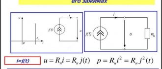
Compensation stabilizers are of two types: parallel and series. Structural diagrams of compensation stabilizers are shown below.
Compensating voltage stabilizer of series type Compensating voltage stabilizer of parallel type
The main elements of all compensation voltage stabilizers are the regulating element P
;
source of reference (reference) voltage AND
;
ES
comparison element ;
DC
amplifier U.
Series compensating regulator
In series-type stabilizers, the control element is connected in series with the input voltage source U0 and the load RH. If for some reason the voltage at the output U1 deviates from its nominal value, then the difference between the reference and output voltages changes. This tension is amplified and affects the regulating element. In this case, the resistance of the regulating element automatically changes and the voltage U0 will be distributed between P and RH in such a way as to compensate for the voltage changes at the load that have occurred.
The regulating element in compensation voltage stabilizers is usually made of transistors. Choosing which is based on the values of the current transfer coefficient h21e, the saturation voltage between the collector and emitter UKENas.
Comparator circuits and DC amplifiers are very often combined and implemented using conventional amplifiers, differential amplifiers or operational amplifiers.
Let's consider the circuit of a series-type compensation voltage stabilizer.
Circuit of a simple series-type compensation voltage stabilizer
In this circuit, transistor VT1 performs the functions of a regulatory element, transistor VT2 is both a comparing and amplifying element, and zener diode VD1 is used as a reference voltage source. The voltage between the base and emitter of transistor VT2 is equal to the difference in voltages UOP and UREG. If for any reason the voltage across the load increases, then the voltage UREG increases, which is applied in the forward direction to the emitter junction of transistor VT2. As a result, the emitter and collector currents of this transistor will increase. Passing through resistance R1, the collector current of transistor VT2 will create a voltage drop across it, which in its polarity is reverse for the emitter junction of transistor VT1. The emitter and collector currents of this transistor will decrease, which will lead to the restoration of the rated voltage at the load. In the same way, you can trace changes in currents when the voltage across the load decreases.
Stepwise adjustment of the output voltage can be done using the reference voltage taken from a chain of series-connected zener diodes. Smooth adjustment is usually made using a voltage divider R3, R4, R5, connected to the output circuit of the stabilizer.
If we neglect the voltage drop at the emitter junction of transistor VT2, then the output voltage of the stabilizer
where R4' and R4'' are the upper and lower parts of the resistor R4, respectively, according to the circuit.
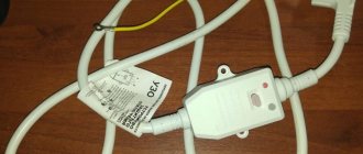
Connecting the stabilizer to 380 V
If we consider the design of the unit, the three-phase stabilizer is made in the form of three single-phase devices, where each is responsible for stabilizing the single-phase voltage. Before starting installation work, you must carefully read the attached instructions and strictly follow all of its points.
Based on the connection method, three-phase stabilizers come in two types. The first type of equipment is characterized by three modules with three terminals, to which the wires are connected. The input and output of the “phase” and the neutral cable (input, three modules and the power circuit) are connected to the terminals. Each individual module is connected to a single-phase network.
The second type of unit also has three single-phase stabilizers, each with 4 terminals for connecting wires. In addition to the “phase” input and output, the “zero” input and output are also connected to them. This allows the neutral wire of the power input to operate separately from the neutral wire of the stabilized electrical network.
Three single-phase units or one three-phase unit can be connected to a three-phase network. Each option has its own advantages.
The first one has this:
- For each phase it becomes possible to select equipment of individual capacity;
- Based on operating conditions, a specific type of unit is selected for each phase;
- Three single-phase devices will be slightly cheaper compared to one three-phase one;
- Single-phase models are easier to transport;
- If service is required, only the device of the three that requires intervention is turned off.
The advantage of connecting a three-phase unit to a similar network:
A three-phase consumer is connected without any problems. However, there are certain disadvantages that should be taken into account: Stabilizers of this type are only electromechanical, and this can become a problem with frequent power surges; Difficulties in transportation. This is determined not only by their weight and dimensions, but also by the fact that they can only be transported in an upright position; It is impossible to distribute power across phases depending on the consumer.
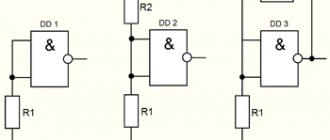
Improving stabilizer parameters
A simple compensation voltage stabilizer circuit can be improved by replacing resistor R1, which powers transistor VT2, with a current stabilizer circuit. This power supply method can significantly increase the stability of the DC amplifier.
In cases where high temperature stability of the Compensation Voltage Stabilizer and low time drift are required (especially at low output voltages), differential amplifier circuits are used. To improve the quality of the output voltage, the DC amplifiers of the stabilizer use operational amplifiers, which have a high gain and low temperature drift. The operational amplifier can be powered directly from the output voltage of the stabilizer.
Current stabilizer circuit. Connection of pins: 1 – to the VT1 collector, pin 2 – to the VT collector. Differential amplifier circuit. Connecting the terminals: 1 – to the emitter VT1, 2 – to the base VT1, 3 – to the cathode of the zener diode VD1, 4 – to the anode of the zener diode VD1, 5 – to the voltage divider.
Calculation of a series stabilizer
An example of calculating a simple series-type compensating voltage stabilizer
Initial conditions: input voltage U0 = 24 V, input voltage instability ΔU0 = ± 2 V, maximum load current INmax = 1.5 A, stabilization coefficient KST ≥ 103. Provide for smooth adjustment of the output voltage ranging from UНmin = 12 V to UНmax = 16 V.
1. Determine the maximum collector-emitter voltage of the regulating transistor VT1:
2. Determine the maximum power dissipated by transistor VT1:
3. According to the calculation data, select transistor VT1, which satisfies the conditions:
These conditions are met by a P216V type transistor with the following parameters: UCEmax = 35 V, IC max = 7.5 A, PC max = 24 W, h21e = 30.
4. To create a reference voltage UOP, we select a Zener diode of type D814A with parameters UCT = 8 V, ICT = 20 mA, rDIF = 6 Ohm.
5. Let’s determine the maximum collector-emitter voltage of amplifying transistor VT2:
6. Based on the condition UCE2max < UCE max, we select a P416 type transistor with h21e = 90 ... 250 as an amplifying element.
7. Assuming that IK2 ≈ IE2 = 10 mA < IC max, we find the resistance of resistor R2:
8. Considering that IR1 = IC(VT2) + IB(VT1), IB(VT1) = IHmax / (1 + h21e(VT1)) = 1.5/(1 + 30) ≈ 48 mA, we determine the resistance R1:
9. Determine the resistance of resistors R3, R4, R5. Let’s agree to assume that if the potentiometer R4 slider is in the uppermost position, then the output voltage of the stabilizer has the minimum value UНmin specified by the condition. In the lowest position of the engine, the output voltage is maximum. Then we can write the equations
Believing
we get
Online calculator for calculating a compensation voltage stabilizer here.
Parallel type compensation stabilizer
In the parallel stabilizer circuit, when the output voltage deviates from the nominal one, an error signal is released equal to the difference between the reference and output voltages. Next, it is amplified and acts on the regulating element connected in parallel with the load. The current of the regulating element IP changes, the voltage drop across the resistor R1 changes, and the voltage at the output U1 = U0 – IBXR1 = const remains stable.
A typical circuit of a parallel-type compensation voltage stabilizer is shown below. These stabilizers use resistors (R1 in the diagram) as a damping device, or if there are high demands on the stability of the stabilizer's output voltage, the current stabilizer described above, which has a high internal resistance, is used.
Circuit of a simple parallel-type compensation voltage stabilizer
Basically, the calculation of the elements of a parallel-type compensation stabilizer is carried out similarly to a series-type stabilizer.
Parallel type stabilizers have low efficiency and are used relatively rarely, in the case of stabilization of high voltages and currents, as well as under variable loads, in contrast to series type stabilizers. Their disadvantage is that with a possible sharp increase in the load current (for example, in the event of a short circuit at the output), increased voltage will be applied to the control element, the value of which may exceed the permissible value. This circumstance must be taken into account when operating the stabilizer.
Theory is good, but you need to practice it all practically. YOU CAN TRY HERE
Schemes of 3-phase loads through 1-phase stabilizers
Devices used in everyday life consume less energy than industrial designs. Therefore, for normal network properties, you can use three voltage stabilizers of equal characteristics that correspond to the load for a 1-phase line.
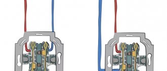
If they use zero separation, then the following scheme is suitable for their installation:
In this diagram, for clarity, the PE protection wire bus is not indicated, and the connection of the stabilizers to it is made in a simplified manner.
The working neutral wire, after the protections located in the switchboard of the house, is divided into the output terminals of each stabilizer. Its bus is created by connecting the output terminals of all three devices in parallel. The zeros to all loads are approached by wire cores from this bus.
The phase terminal, which is included in each stabilizer, is connected to its terminals of the protective device, the output terminal with a group of circuit breakers that supply power to consumers.
If you combine working outgoing and incoming zeros, this makes the circuit simpler. But for some models, this method disrupts some control algorithms in the event of an accident. Therefore, manufacturers carry out this separation.
The diagram shows the connection of similar stabilizers to 3-phase loads.
All diagrams are shown to familiarize yourself with the principle of operation of voltage stabilizers. Therefore, the diagram does not depict switching devices, distribution boxes and other devices.
Connecting the stabilizer to the network
Watch this video on YouTube