To determine and control the amount of electricity consumed, it is necessary to correctly connect the meter.
Let's consider existing methods for connecting three-phase metering devices. The intended connection diagram for the meter will be determined by its type. Today there are several types of three-phase meters:
- direct connection (meters 0.4 kV);
- indirect connection (via instrument transformers);
- semi-indirect inclusion.
Semi-indirect counters
This connection occurs through current transformers. There are a large number of schemes for this inclusion, but the most common among them are:
- The ten-wire connection diagram is the simplest, and therefore the most popular. To connect, you must follow the order of 11 wires from right to left: the first three are phase A, the second three are phase B, 7-9 for phase C, 10 are neutral.
- Connection via terminal box - it is more complicated than the first one. The connection is made using test blocks;
- A star connection, like the previous one, is quite complex, but requires fewer wires. First, the first unipolar outputs of the secondary winding are collected at a common point, and the next three from the other outputs are directed to the meter, and the current windings are also connected.
Tools and materials
Replacing or installing a new electric meter yourself will require the use of special tools:
- comfortable pliers with rubberized handles;
- a set of non-conductive screwdrivers;
- sharp knife for stripping insulation from wires;
- insulating materials;
- measuring multimeter.
Types of electric meters may differ in their fixation methods, so it is necessary to purchase not only wires with a certain cross-section, insulators and RCDs with circuit breakers, but also fasteners and a current transformer. Installation is carried out in the subscriber panel using mounting strips.
How to connect single-phase
A single-phase electric meter can only be connected to a corresponding single-phase network.
For installation you will need:
- screwdriver - for manipulating the terminal screw;
- knife - for stripping wire insulation;
- multimeter - to determine the phase.
In a single-phase electrical network, there are two wires at the input from the electricity supplier or transformer. They are also present if current transformers are operating in the network. It should be noted that the input wiring has already been stripped of insulation to the required level to completely fit under the terminal.
Specialist's note: do not remove insulation from the input wires to avoid problems with Energonadzor. After all, it is the excessive removal of insulation that allows you to connect devices in front of the meter, and thereby steal electricity.
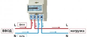
There are four terminals on a single-phase electric meter. They are usually numbered from left to right:
- terminal 1 – for phase input;
- terminal 2 – for phase output;
- terminal 3 – for zero input;
- terminal 4 – for zero output.
The input wires of a single-phase network are rarely made of different colors. Therefore, you need to use a multimeter to determine where the phase is and where the zero is.
The wires are connected in series:
- First, the input phase is connected to terminal 1.
- Then, the input zero is connected to terminal 3.
- Then you need to strip the insulation on the output wires, connect it to the machine, and connect it to terminal 2 of the output phase wires, and to terminal 3 of the output zero wires.
On old induction meters, the terminal is tightened with one screw, on modern ones - with two. In any case, you should not tighten them too much. Since their strength will still be checked by the Energosbyt controller.
Step-by-step instructions for installing the meter
First of all, we prepare the kit for work. We will need the following:
- counter and shield;
- installation tools with pre-insulated handles;
- insulators;
- switches (automatic);
- wires;
- fasteners (screws and nuts);
- voltage meter;
- DIN rails.
Metering panelInstallation of a meter
Next we work in this order.
Second step
We install the metering device into the body of the protective shield. Fastening is carried out using special clamps from the kit.
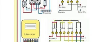
Installation of the platform Prepare the installation wires We insert three phases into the meter, connect the lower terminals. Phase A enters terminal 1 of the meter, exits terminal 2 to the load; phase B enters terminal 3, exits into 4 and phase C enters 5, and exits from 6. 7 and 8 are zero
Third step
We install switches. We will attach them to the DIN rail with a special spring-loaded latch. We first fix the rail itself with screws to the support insulators.
Fourth step
We install grounding and protective busbars. We attach them to a DIN rail or insulators in the body of the protective shield. Fixation is carried out with screws and nuts. We place the buses at such a distance that the possibility of shorting the wires is excluded.
First, we connect the load to the switches, then we connect the machines to the meter, and only after that we connect the meter itself.
JumperConnecting OPS
Fifth step
We connect the loads. We connect the phase to the lower terminals of the switches, connect the zero to the zero bus, and connect the ground wire to the ground bus.
Sixth step
We install jumpers connecting the clamps on top of our machines. Jumpers are sold in specialized stores. We first buy the required number of jumpers according to the number of machines.
Zero bus Fasten the wire to the grounding bolt
Seventh step
We connect the electric meter to the load. To do this, we connect the “phase” output (which is the third terminal of the metering device) to the upper terminals of the machines. Next, we connect the “zero” output (represented by the fourth terminal of the metering device) to the zero bus.
Eighth step
We fix the body of the electric meter panel on a wall or other suitable flat base. Maintain a comfortable height.
Ninth step
We find phase, zero and grounding. If there is no grounding, we check each core with a special indicator. This simple device will help us find the phase. If there is a ground connection, you will easily recognize it - usually this wire is painted or marked green.
Thirteenth step
We contact the local energy sales office for additional checks and sealing of metering equipment.
Work completed
At this point, the work of manually installing and connecting the electric meter is completed.
Congratulations, you have successfully completed all the activities and saved money on the services of third-party installers!
Close the protective covers of the metering board and fasten them with self-tapping screws
Connecting a three-phase semi-indirect meter
These devices are connected to the network through current transformers, making it possible to use them in networks with fairly high powers (up to 60 kW). Using this accounting method, to determine the flow rate, you need to multiply the difference in readings by the set transformation ratio.
There are several types of connection for semi-indirect connection meters.
1 Star connection of current transformers
The process of connecting wires looks like this:
- contacts 3, 6, 9, 10 – are closed and connected to the neutral wire;
- contacts I2 - closed, connected to terminal 11;
- 1 – to I1 phase A;
- 4 – to I1 phase B;
- 7 – to I1 phase C;
- 2 – to L1 phase A;
- 5 – to L1 phase B;
- 8 – to L1 phase C.
Figure - Star connection diagram
Connecting a three-phase indirect meter
These devices are designed to perform electricity metering at high-voltage connections (6-10 kV and more), the connection is realized using voltage and current transformers.
Below are the main diagrams for connecting three-phase meters via current and voltage transformers:
1) Scheme for connecting a three-element meter to a four-wire network with a grounded neutral: (figure below)
2) Scheme for connecting a three-element meter to a four-wire network. Three current transformers, direct connection to voltage:(picture below)
3) Scheme for connecting a three-element meter to a three-wire line - two current transformers, three voltage transformers: (figure below)
When connecting a three-element meter according to scheme No. 3:
- phase B current is calculated with the subtraction of the zero-sequence current;
- direct, negative and zero sequence currents of the fundamental frequency are not used (symmetrical components);
- active and reactive power in phase B are calculated by subtracting the zero-sequence current from the phase current;
- Electrical energy accounting is carried out taking into account the above comments.
4) Scheme for connecting a two-element meter to a three-wire line - two current transformers, two voltage transformers (figure below)
When connecting the meter according to schemes No. 4 and No. 5:
- The zero sequence voltage of the fundamental frequency is not measured (symmetrical components);
- direct, negative and zero sequence currents of the fundamental frequency (symmetrical components) are not measured;
- connection capacities are calculated using formulas;
- Electrical energy accounting is carried out taking into account the above comments.
5) Connection diagram of a two-element meter to a three-wire line - two current transformers, direct voltage connection (figure below)
Attention!: The possibility of connecting according to a specific scheme must be indicated in the passport or manual for a specific type of meter. {SOURCE}
{SOURCE}
Preliminary stage
Connecting an electric meter (ES) is the final stage of electrical installation work.
Before installing a three-phase ES, you must first have a wiring diagram. The device must be checked for the presence of seals on the casing screws. These seals must indicate the year and quarter of the last inspection and the seal of the verifier. When connecting wires to the clamps, it is better to make a reserve of 70-80 mm. In the future, such a measure will allow measuring power/current consumption and rewiring if the circuit was assembled incorrectly.
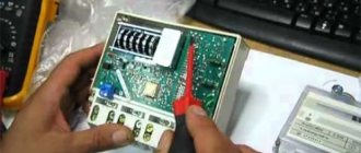
Each wire must be clamped in the terminal box with two screws (they are clearly visible in the photo below). The top screw is tightened first. Before tightening the lower one, you need to make sure that the upper wire is clamped by first tugging on it. If a stranded wire is used when connecting the meter, it must first be crimped with a tip.
Figure 1 – TS Mercury 231
Next, we will consider typical diagrams for connecting a three-phase meter to the electrical network.
Connections
- three-wire – for a network without a neutral wire;
- four-wire - with a neutral wire.
The connection of a three-phase meter should be carried out taking into account the following feature: devices can be connected either directly to the network or through current transformers. This depends on the current strength in the network: up to 100A - direct connection is allowed, above - through a transformer.
Three-phase meters also differ in how they are connected to the network:
- direct (direct) inclusion;
- semi-indirect installation (via a current transformer);
- indirect (using current and voltage transformers) connection.
What to consider when installing equipment
You should not do the connection of a three-phase meter yourself. Errors are fraught not only with incorrect measurements - there is a risk of device breakdown, short circuit, and other negative consequences. For installation, you should invite a certified specialist with the appropriate clearance group, who thoroughly knows the schemes, principles and installation technologies.
Installation recommendations:
- Before connecting a three-phase meter, you must turn off the power supply. To monitor the presence of voltage on the wiring, use a special indicator;
- the equipment is mounted on a DIN rail at a height of one to one and a half meters from the floor surface. The meter must be reliably protected from the external environment, so installation in an open space is not allowed. It is advisable to use a special operational cabinet of the Pulsar brand produced by TEPLOVODOKHRAN. It provides reliable protection from external factors and simplifies the operation and maintenance of equipment. For connection, exclusively copper conductors are used, the cross-section of which must correspond to the planned load;
- the connection is carried out in strict accordance with the diagram, otherwise the electric meter will not work. To determine the phases, special equipment is used;
- the insulating layer from the conductors is removed approximately 2 cm from the ends: the ends stripped of insulation are aligned, inserted into the contact recesses and securely fixed using fasteners;
- after connecting all conductors, equipment is installed to protect the facility from short circuits;
- voltage is applied only after all contacts have been installed and carefully secured. If the three-phase meter is connected correctly, the indicator lights up after power is supplied;
- After installation, the electricity meter is sealed.
Three-phase meters with semi-indirect connection
Electric meters "Mercury" with a semi-indirect connection principle are connected to the 380V alternating current network through a transformer. Thanks to this, it becomes possible to meter electricity with high network power. At the same time, in the process of calculating the resources used, the transformation coefficient must be taken into account. Today, there are quite a lot of semi-indirect circuits, the most popular of which are the following options:
- transformer connection circuit according to the “star” principle;
- ten-wire connection;
- connection diagram using test terminal boxes;
- by combining current and voltage circuits.
Considering the disadvantages of a semi-indirect connection scheme, I would like to note the difficulty of carrying out scheduled inspections by energy sales regulatory authorities.
Advantages of electronic meters
The demand for electronic measuring instruments is constantly growing. Previously, only induction structures were installed, but their simplicity and primitiveness have many disadvantages. The advantages of electronic meters include the following:
- High accuracy class, which is maintained at low or extreme, rapidly changing loads. The induction design was characterized by relatively low measurement accuracy, especially under variable loads.
- Installed in the case of multi-tariff metering of the amount of energy consumed. Today, to save money in some regions, the cost of 1 kW may depend on the time of day or other indicators.
- There are quite a few models on sale that can not only calculate the amount of energy expended, but also control its quality. Of course, other measuring instruments can be installed for this purpose, but by purchasing such a meter you can save significantly.
- The information is easy to read as it is written to the internal memory of the device. To read it, an analog display is installed.
- It is very difficult to change readings if an electronic meter is installed. Any attempt at unauthorized access by the device is recorded.
- The design, as a rule, has smaller dimensions, which allows their installation in small distribution boards with other equipment.
- Most models have a service life of 30 years. In this case, maintenance is performed every 10 years.
The only significant drawback is the higher price when compared with the cost of induction models. In addition, the device is susceptible to lightning impulses, which very often cause it to fail.
Transformer connection diagrams
The reliability of the entire measuring system as a whole depends on which connection diagram for a three-phase meter via current transformers is used in this case. When choosing one or another of them, the following requirements must be taken into account:
- It is prohibited to turn on the meter through current transformers if it is intended for direct connection to the measuring network;
- When indirectly connected, it is necessary to examine the electrical circuit and determine the transformer model suitable for it (in terms of power and current);
Important! Before choosing a transformer for each specific situation, first of all, you should pay attention to its conversion coefficient, which has different values for different models. Before choosing a current transformer for a specific measuring circuit, you need to carefully study the order of the contacts to which the three-phase meter is connected
Before choosing a current transformer for a specific measuring circuit, you need to carefully study the order of the contacts to which the three-phase meter is connected.
Next, we will consider a specific diagram for connecting the meter to a three-phase circuit (see the figure below).
Schematic diagram of connection
Since the general principle of operation of all electric meters is the same, the purpose of the terminals on them is also similar. For phase “A” it looks like this:
- Contact K1 is needed to connect the current wire and one end of the transformer voltage coil to the meter;
- Terminal K2 is designed to connect the load to this phase line;
- Contact K3 is used to connect the second end of the CT voltage winding.
In the same way, the second phase “B” is connected to the meter (via terminals K4, K5 and K6), as well as the third phase “C” with contacts K7, K8, K9.
Note! Terminal K10 is the common zero, relative to it, phase voltages with the following three designations are supplied to K1, K4 and K7 of the meter: “A”, “B” and “C”. The disadvantages of the combined circuit include a large error in measuring power consumption, as well as the inability to detect a breakdown in the transformer windings
The disadvantages of the combined circuit include a large error in measuring power consumption, as well as the inability to detect a breakdown in the transformer windings.
In practice, a simpler scheme for connecting an electric meter is most often used, according to which a combined connection of secondary current circuits is carried out. It functions as follows:
- Phase wires are connected to the current contact of the meter from the circuit breaker. To simplify the circuit, the second phase voltage terminal is connected to it;
- We select the phase input of the coil so that it is also the output of the primary winding of the CT. It is subsequently connected to the load through distribution circuits;
- The beginning of the secondary transformer winding is connected to the first contact of the meter's current coil (according to one of the phases);
- The end of the secondary transformer coil is connected to the end of the current winding of the connected counter mechanism.
All remaining phases are connected in the same way.
The connection and grounding of the secondary windings of the meter is carried out in accordance with the requirements of the PUE (they are carried out according to the “star” circuit).
Education of a full star
Thanks to this organization of connecting contacts, a seven-wire circuit is obtained (as opposed to a 10-pin circuit). In conclusion, it should be recalled that when connecting via a TT, a competent choice of its type is important.
Choosing the right current transformer means taking into account that the maximum permissible current value in the secondary winding cannot exceed 40% of the nominal value, and the minimum - 5%. All phase voltages connected to the meter must follow a certain order, which is controlled using a special device (phase meter).
Three-phase meter "Mercury 230"
This is an advanced device that has a telemetry output with a special interface that is needed to exchange information. An electronic seal is placed on the device for automatic diagnosis of emerging problems. This is a direct-flow unit for calculating electrical energy in a three-wire and four-wire network. It can be connected using the direct or transformer method.
Note! By connecting a transformer, energy readings can be made on objects that have a high load.
The three-phase meter has a liquid crystal display, which receives data in kilowatts and hours. Equipped with eight digits. The first six digits indicate whole numbers, and the last six digits indicate hundredths. Accuracy of 1.0 kilowatt. Operating temperature from −40 to +55 degrees Celsius.
Possible problems
There should be no technical problems with connection. In this case, the meter readings will be displayed correctly on the meter display.
Let's look at various situations and possible problems:
- Connections at home with a normal load not exceeding 10 kW. In this case, there is a problem with registering the device. The sales organization has the right not to register and seal it. Arguing that the electric meter is not used for its intended purpose. Although there are no strict rules, the inspector will formally be right. Everything will depend on the inspector;
- Technical conditions have been issued for connecting the house to a three-phase network, but there are no technical capabilities. In this case, the inspector has the right to register the device and seal it. But he will give a temporary permit that lasts for years until the power grid corrects the situation;
- Permission was issued to connect to a single-phase network with a power of 15 kW. Electrical networks rarely do this, but it happens in life. Single-phase meters are designed for currents not exceeding 60A. And a load of 15 kW consumes a current of 75 A. A three-phase direct connection meter is designed for 100 A. Therefore, as an exception, energy sales will give permission to install a three-phase meter;
- Installing a meter in a garage or gardening community. Everything is simple here. The local electrician does not care at all what kind of metering device is installed in the box or house. The main thing is that it shows the energy consumption correctly.
From the above we can conclude that three-phase electricity meters can be used in a single-phase network. Electricity consumption readings are displayed correctly. However, problems arise during registration, the solution of which depends on the inspector of the service organization.
How to install an electricity meter?
To control electricity consumption, it is necessary to install meters. They can be settlement ones for calculating and paying for the consumed amount of electricity to the relevant organizations, or control ones for carrying out measurements at control points and nodes. The first type of devices is usually installed by service organizations that supply electricity to end consumers, perform sealing, periodic checks, etc. Control devices are installed in-house or with the assistance of experienced electricians. That is, there is a need to install an electricity meter yourself.
How to choose the right place to install an electric meter?
Before installing an electricity meter, you must select a suitable room and installation location that complies with the standards prescribed in the latest edition of the PUE:
- The temperature at which operation is allowed is from 0°C to +40°C. If it is impossible to ensure such a mode, it is necessary to ensure installation in insulated steel cabinets with a heating system.
- The location of the display or window with measurement readings should be at a level of 0.8 to 1.7 m. Readings should be taken without opening the cabinet, using the window provided for this purpose.
- Installation is allowed on walls, panels, cabinets and relay compartments.
- Fastening should be carried out on metal, plastic or wooden panels.
- When installing induction meters, an inclination angle of 1° must be observed.
- All wires must be color coded and have a cross-section of at least 12 mm.
- Switches and fuses must be located at a distance of up to 10 m from the meter.
Summarizing the above, we can conclude that meters should be located in rooms with optimal temperature in a convenient and accessible location. It is also recommended, in order to save money, to place them directly at the point of entry into the building.
Which counter should I choose?
There are two types of meters: single-phase and three-phase. The first option is suitable for most ordinary consumers when organizing household or office networks that are not designed for high rated currents or connecting industrial equipment. The second option is used for industrial purposes. Therefore, it is necessary to determine in advance the purpose of the electrical network and its technical capabilities, and when purchasing, pay attention to the passport characteristics:
- markings that reflect parameters for current, load and maximum operating voltage;
- the presence of a seal indicating that tests have been completed for the reliability of measurements and compliance with Gosstandart.
Connecting a single-phase meter
Before connecting the electricity meter, you need to look at the connection diagram located on the back of the cover covering the terminals. The correct connection to the terminals of the following wires must be marked there:
- phase input;
- zero input;
- phase output;
- output zero.
Types of metering devices
Depending on the principle of operation, three-phase electricity meters can be:
- electromechanical (induction);
- electronic.
The first option is discussed above. Such metering devices have recently been used less frequently, as they have a low accuracy class, have a small range of operating temperatures and do not allow saving electricity if it is possible to maintain multi-tariff metering of electricity consumption.
Electronic metering devices are free from these disadvantages, since they do not contain mechanical parts. In addition, thanks to electronic filling, such devices can transmit readings remotely. They can be freely mounted even outdoors on power poles. Of course, such devices cost several times more than their induction counterparts, but this cost can easily be recouped through the use of multi-tariff metering, for example, by using powerful consumers at night.
What errors occur when connecting and how to prevent them
Errors during connection occur only in the fact that the contacts were incorrectly connected to each other. The phases to the reading device are incorrectly selected and connected. The main reason for this is the lack of experience with electrical equipment and circuit diagrams, as well as the lack of complete adherence to the instructions provided for the reading device.
Note! To avoid mistakes, it is only recommended to carefully read the manual or call a specialist who will not only install a three-phase meter, but also help you configure it to the existing and current tariffs.
In general, the three-phase meter “Mercury 230” is an improved device, thanks to which it is much easier to read utility bills. It has its advantages and disadvantages. It works very simply. Connects semi-indirectly, directly and indirectly. Connection errors do not occur only if such things are handled by a professional technician or a person who understands electrical circuits. Therefore, it is better to entrust the moment of connection to specialists.
Consequences of incorrect connection
In addition, an unprofessional approach to installing electrical equipment has a detrimental effect on it during operation.
In case of cable overload (current exceeds the nominal value), poor connection of contacts or connection of copper and aluminum wiring, they will soon manifest themselves. In this case, emergency situations are inevitable. And their first sign will be the smell of burnt wiring.
To properly connect an electric meter, you need to have knowledge of electrical engineering concepts. If you install it yourself, you can watch video tutorials on this topic. However, we should not forget that a professional approach can save not only property, but also life. Therefore, if you are not confident in your capabilities, then it is better to minimize the risks.
To control and account for consumed electrical energy, you need a special device - an electric meter. Both in large industrial enterprises and in private apartments, when concluding an agreement for the supply of electricity, this device cannot be avoided.
When installing a meter to calculate consumed electricity, you must correctly connect it to the power supply circuit.
Electricity meters can be either single-phase or three-phase, with direct or indirect connection.
In this article we will tell you in detail how to independently connect both types of electricity meters.
Conclusions and useful video on the topic
Connecting it yourself saves money, but requires basic electrical knowledge. If you adhere to safety regulations and use the diagram and step-by-step instructions, the work will not take much time. However, if there is no entrance switch, you will have to call a technician to turn off the power to the riser (entrance). Otherwise, the video will be the best help for those who still decide to do everything with their own hands. But then call an Energonadzor inspector to inspect the meter and install a seal.
HelpfulNot helpful
No tags for this post.
Protective and transition devices
Any three-phase electricity meter connected to high-voltage networks through current transformers must be protected from overvoltages that often occur in power supply lines. For this purpose, special devices are installed in series with it to limit the voltages that arise in the line in an emergency. They are found under various names, the most common of which is oin.
This device, in its functionality, resembles a circuit breaker. But it is not triggered by overcurrent, but is used as a voltage limiter on the section of the supply line into which the three-phase meter is connected.
Below is a diagram according to which this device is installed in the circuit of the equipment it protects.
Before installing a three-phase meter in the supply circuit, experts advise using another special device connected to the terminal block of the meter itself.
The indicated product, found under the designation IKK, has in its design a number of jumpers that allow you to switch the connection in a user-friendly way. The appearance of this device and the diagram for connecting it to the power circuit are shown in the photo below.
From this photo it is clear that when using IKK, the installation and dismantling of any type of metering device is significantly simplified, which is very convenient when carrying out their repair, for example.
Additional installation of the IKK is carried out by connecting it in parallel to an existing terminal block.
In the final part of the review, we note that the previously discussed meter switching schemes are selected depending on their operating conditions and the nature of the existing electrical network. To organize their correct connection, it is important to take into account all the factors that affect the performance of a particular counting device, determined not only by its class, but also by the features of the reading-taking mechanism.
You may also like
Three-phase electricity meter “Pulsar 3/T3” RS485 without button
Designed for measuring and metering active or reactive electrical energy in single or multi-tariff mode. The meter can be used autonomously or as part of automated systems for monitoring and accounting of electricity (ASKUE).
Interverification interval - 16 years; Average service life - 32 years; Average time between failures - 318,160 hours; The service life of the meter from one lithium battery is at least 16 years.
from 6328₽
Buy in bulk
Three-phase electricity meter “Pulsar 3/T3”
Designed for measuring and metering active or reactive electrical energy in single or multi-tariff mode. The meter can be used autonomously or as part of automated systems for monitoring and accounting of electricity (ASKUE).
Interverification interval - 16 years; Average service life - 32 years; Average time between failures - 318,160 hours; The service life of the meter from one lithium battery is at least 16 years.
Buy in bulk
Preparatory work
In general, connecting an electric meter, the circuit of which is known, will not be difficult.
We sorted out the contacts. Video: connecting a single-phase single-tariff electric energy meter Connecting a three-phase electric meter There are two types of connecting a three-phase meter, direct and indirect, through isolating current transformers.
The box consists of two main parts: an outer one - a protective cover with an inner door, which includes one or more DIN rails, their number depends on how many installation positions the box is designed for. The power consumed in this case is distributed between three phase conductors, as a result of which the current in each of them is reduced to approximately 2.5 Amperes. However, in real life, an input machine can be installed behind the meter along the flow of electricity.
It is necessary to observe the phasing of the winding connection, otherwise the meter readings will be incorrect. And many people think that only a professional electrician can do such work. Additional installation of the IKK is carried out by connecting it in parallel to an existing terminal block.
Installing an electricity meter for a garage is similar. Contacts of automatic switches Let's start with the input circuit breaker. All single-phase meters, both electronic and induction, have only four terminals for connection: Contact 1 - for connecting the phase supply wire; Contact 2 - for connecting the phase wire going to the electrical receivers; Contact 3 - for connecting the neutral supply wire; Contact 4 - for connecting the neutral wire going to the electrical receivers.
They can be either metal or plastic. If the induction counter is placed in a horizontal position, it stops. From these terminals, the conductors are connected to a fire protection RCD, after which the electricity is distributed among single-pole circuit breakers, and the neutral working conductor is connected to a common zero bus. As a rule, in most cases, such a device is a two-pole circuit breaker.
Installation of an electric meter and modular equipment
From the input machine, this is usually a two-pole device, one phase wire is connected to the 1st contact of the electric meter, and a jumper connects the second terminal to the distribution machine. How to connect the machine, as well as how to connect the meter, can be seen from the attached diagrams. To avoid confusion if any faults occur, be sure to mark your circuit breakers and meter with the apartment number. From the terminals of the secondary winding of the current transformer, phase A, wire with cross section 1. External conditions should also be taken into account - temperature, humidity and others. The transition to a modern and universal three-phase power supply circuit is also preferable from the point of view of maintaining the required temperature balance, ensuring safe operating conditions for the entire power supply system.
Pulling contacts Surely, if a person has installed electrical wiring in an apartment on his own, he already knows that the contacts of the connections must be tight enough to prevent heating and failure of the wires. Transformer connection meters are mainly used in metering units of industrial enterprises. Most often it is installed in the corridor or at the front door. This should be the case according to the PUE, but if the input machine cannot be sealed, the network organization will not allow such a meter connection scheme. Now, you need to distribute the phase coming from the meter among all single-pole circuit breakers outgoing in directions. Do-it-yourself installation of the SIP input panel and meter
Division of responsibility for electrical appliances
But the connection diagram of the meter must provide for the possibility of unhindered access to it. The inspector must at any time (upon demand or request) be able to take readings, install a seal, check the device and inspect it. If a hard-to-reach place is chosen to connect the electric meter, the inspector may issue a fine or transfer the apartment to payment according to the general tariff, calculated by the number of residents.
When it comes to connecting an electricity meter in a non-privatized, municipal apartment, where it is located on the site, relocation is possible only with the permission of the management company, HOA, GSK. The gardening partnership is responsible for the dacha and the land plot, and the garage cooperative is responsible for the garage. All work in this case is performed by an electrician on staff or by a contractor on the basis of a contract. Even if you have your own meter, connection is the responsibility of the authorities responsible for energy supply.
People often ask how to connect an electric meter in a private house? Previously, this could be done in any room, and most often it was in the hallway, boiler room or pantry. Now it is better if it is installed on the wall, so that during the inspection the inspector can record the readings, verify the payment, and establish the existence and amount of the debt. It is allowed to install a metering device on any structure. The main thing is that the input - the supply cable - is visible. But a switch, “traffic jams” or a machine may be in the house.
Selecting a meter
Before connecting a 3-phase meter suitable for a private home, you need to make sure that the use of this brand of device is provided for by the type of supply network. Next, you will need to find out what operating current the purchased meter should be designed for. In this case, one should proceed from the amount of power taken into account by the device and the power consumed in the load. As a rule, in this case, they are guided by the rating of the input machine, according to which the following options are possible:
- when using a switch with a setting of “40”, the operating current of the meter should be 60 Amperes;
- with a machine rating of 40-60 Amperes, you should purchase a metering device with a current limit of 100 Amperes.
A big advantage of a three-phase meter is the ability to record the load graph and keep track of power consumption for any time period
When choosing such a device, it is important to inquire about its accuracy class (from 0.2 to 2.5) and permissible temperature range. It is desirable that the last indicator be as wide as possible (from – 20º C to 50º C)
Advantages of three-phase design
- Such meters are universal: they work perfectly in traditional 220 V network circuits. They connect to metering devices directly or through a transformer. Manufacturers equip the equipment with additional options:
- assessment, accounting of active and reactive energy of three-phase current;
- control of voltage sag in the network;
- 4 options for electricity metering tariff plans, allowing you to choose one that is convenient for the consumer;
- daily or monthly recording of indicators;
- setting up system elements, displaying indicators on the monitor;
- variability of accuracy class; models are produced with an error of readings from 2.5% to 0.2.
Connecting a three-phase semi-indirect meter
These devices are connected to the network through current transformers, making it possible to use them in networks with fairly high powers (up to 60 kW). Using this accounting method, to determine the flow rate, you need to multiply the difference in readings by the set transformation ratio.
There are several types of connection for semi-indirect connection meters.
1 Star connection of current transformers
The process of connecting wires looks like this:
- contacts 3, 6, 9, 10 – are closed and connected to the neutral wire;
- contacts I2 - closed, connected to terminal 11;
- 1 – to I1 phase A;
- 4 – to I1 phase B;
- 7 – to I1 phase C;
- 2 – to L1 phase A;
- 5 – to L1 phase B;
- 8 – to L1 phase C.
Figure - Star connection diagram
Ten-wire circuit for switching on the meter
10-wire circuit
This circuit is characterized by improved electrical safety, due to the isolation of current and voltage circuits from each other.
Connecting a three-phase indirect meter
These devices are designed to perform electricity metering at high-voltage connections (6-10 kV and more), the connection is realized using voltage and current transformers.
Below are the main diagrams for connecting three-phase meters via current and voltage transformers:
1) Scheme for connecting a three-element meter to a four-wire network with a grounded neutral: (figure below) 2) Scheme for connecting a three-element meter to a four-wire network. Three current transformers, direct connection to voltage: (figure below) 3) Connection diagram of a three-element meter to a three-wire line - two current transformers, three voltage transformers: (figure below)
When connecting a three-element meter according to scheme No. 3:
- phase B current is calculated with the subtraction of the zero-sequence current;
- direct, negative and zero sequence currents of the fundamental frequency are not used (symmetrical components);
- active and reactive power in phase B are calculated by subtracting the zero-sequence current from the phase current;
- Electrical energy accounting is carried out taking into account the above comments.
4) Scheme for connecting a two-element meter to a three-wire line - two current transformers, two voltage transformers (figure below)
When connecting the meter according to schemes No. 4 and No. 5:
- The zero sequence voltage of the fundamental frequency is not measured (symmetrical components);
- direct, negative and zero sequence currents of the fundamental frequency (symmetrical components) are not measured;
- connection capacities are calculated using formulas;
- Electrical energy accounting is carried out taking into account the above comments.
5) Connection diagram of a two-element meter to a three-wire line - two current transformers, direct voltage connection (figure below)
Attention!: The possibility of connecting according to a specific scheme must be indicated in the passport or manual for a specific type of meter. Direct connection three-phase meter Energomera
Direct connection three-phase meter Energomera
Today's article is devoted to disassembling the direct connection meter Energomer TsE 6803V. Let me remind you that I already have a similar article about the design of a single-phase Energomer meter. There is also information on how the meter counts electricity.
This time – not one, but three phases!
For those who are more deeply interested in the topic, I have already written in detail in another article how the three phases differ from one.
I have another popular article on such meters - about connecting and installing three-phase meters. It contains very detailed instructions on how to secure and connect such meters.
I came across a three-phase meter that has been taken out of service. We'll take it apart down to the screw, get ready!
Direct connection of a three-phase device
The simplest connection method, which resembles a standard installation diagram for a single-phase meter, is the direct connection of an electricity consumption monitoring device. The main distinguishing feature of such devices is the presence of a larger number of terminal contacts than in single-phase analogues. In turn, the installation process of the three-phase Mercury device itself consists of a certain sequence of actions .
Read also: How to take electric meter readings day and night
- The supply conductors are stripped of insulation and connected to a three-phase type protective circuit breaker.
- Immediately behind the machine, 3 phase conductors are connected. to paired terminal contacts starting from the right side of the device. Accordingly, the phase wiring is output from odd-numbered terminals.
- The neutral conductor is connected respectively to the two remaining contacts 7 and 8.
- Three-pole circuit breakers are installed immediately behind the electric meter.
- Standard household equipment can also be connected to the Mercury meter. For this purpose, it is necessary to tap a single-pole circuit breaker from any phase wire and, naturally, from the neutral terminal.
If it is planned to install several single-phase consumers, then they must be evenly distributed, for which they are connected through automatic machines from different phase conductors taken immediately after the electric meter.
Types of inclusions and their features
Depending on the method of switching the windings of current transformers, three-phase meters installed in electrical networks are connected according to the following schemes:
- direct connection;
- indirect inclusion;
- semi-indirect connection.
Direct inclusion is called direct inclusion, and to understand the differences between the second and third types, it is necessary to take into account the scope of their application. Purely indirect connection is the open installation of current transformers (CTs) on high-voltage power cables of a three-phase line (6-10 kV). This method is found only at power substations and at large industrial enterprises with their own power distribution networks. In domestic conditions, this type of connection of transformers is not used.
Electrical panel installation
To install the CO 505 meter, we use an Apartment plastic panel of the ShchK type (I remind you that this is a low-budget replacement option). Here is the lower part of the electrical panel, which is attached to the wall:
Electrical panel for the meter
Self-tapping screws indicate three plastic inserts included in the shield kit, to which the meter will be attached. These inserts move freely (and can fall out freely) in their grooves.
The CO-505 meter on the back has three mounting holes through which it is attached to these inserts:
Rear view of the CO505 electricity meter
Now you need to securely fasten the back panel of the electrical panel to the wall:
Installation of electrical panel for the meter
It is very important that the back panel is secured without kinks, so that later you can put the top cover on it without any problems and that the machines fit smoothly. For installation we use a carrier (powered from neighbors), a hammer drill, 6 or 8 dowels, self-tapping screws
I usually don’t disturb my neighbors, I connect via a two-pole circuit breaker to the existing wires in the apartment, and carefully make the necessary holes for the dowels. This method is also discussed in the article about laying the cable to the meter, see the link at the beginning of the article.
Device of a three-phase meter Energomer TsE6803V
The appearance of the counter is shown on the left, at the beginning of the article. All photos, as usual, can be enlarged.
Turn it over, view of the terminals. As always in such devices, the terminals are of very high quality. After all, they are sealed, and there is no access to them.
Three-phase meter terminals
Back view. There is no DIN rail mounting, only screws. Although the kit may include an adapter strip for DIN rail.
Rear view, mounting holes
The top cover is sealed with two seals. If they are accidentally torn off, then such a counter must be submitted for verification. In practice, you will have to buy a new one.
But we don’t care anymore, we’re filming:
Device of a three-phase direct connection meter Energomer
We see a printed circuit board and a reading display device.
Now more details. This is a stepper motor, on the axis of which wheels with numbers are mounted. The motor is connected to the board with two wires:
Three-phase meter Energomer tse6803v. Mechanical indicator device
Voltage pulses are supplied to the motor, and they are also sent to the LED, which blinks in time with the movement of the numbers.
Further. A controller that contains a program for converting a voltage proportional to the flowing current into pulses for a stepper motor.
The device of a three-phase meter Energomer tse6803v.
There is also a serial port with optical isolation.
Fee on the other side:
The device of a three-phase meter Energomer tse6803v. Printed circuit board
Here are the input circuits, which are built on the basis of voltage dividers assembled on resistors and capacitors.
It is worth saying that these parts have a nominal error percentage (for example, capacitors - 10%), but I did not find any adjustment on the board. Although, most likely, the accuracy of measurements is determined by the accuracy class of the divider resistors, and capacitors are used to smooth out ripples. And the resistors, judging by the color markings, have errors of 0.5 and 1%.
How the three-phase Energomer meter works, input circuits
Red wires indicate voltage supply from each phase. Between each of them there is a linear voltage of 380V. They are soldered to the inputs of the dividers.
Next, we will consider devices that convert current into voltage. Everything is not so simple there, and Ohm’s law alone cannot do it.
How the three-phase Energomer meter works, input circuits
How does the three-phase meter Energomer work, input terminals
Everything is clear with the zero terminal,
How does the three-phase meter Energomer work, input terminals
but let’s take a closer look at the phase one:
How the three-phase meter Energomer works, disassembled phase terminal
How the three-phase meter Energomer works, disassembled phase terminal
A coil that is located in a phase loop.
How the three-phase Energomer meter works, disassembled phase terminal with transformer
How the three-phase meter Energomer works, disassembled phase terminal
There is something similar in a single-phase meter (I gave the link above), but there this autotransformer or divider is implemented more simply.
By the way, despite the fact that the meter is called Direct Connection, it still has a transformer at the input, as can be seen from the photo of the design.
General information
A three-phase electrical network simplifies the creation and operation of electrical machines, such as, for example, the asynchronous motor, which has become the basis of many industrial machines. All residential buildings are connected to a three-phase alternating voltage network , and the owners of most private buildings use 380 volts to electrify their properties.
The compatibility of an industrial three-phase electrical network with a household one is associated with several options for consumer connection schemes. Thanks to this, consumers can use either 220 volts or 380 volts and distribute the load between the phases.
As a rule, a three-phase electrical network is four-wire - three linear wires and one zero. In linear wires, the voltage phase is consistently shifted by 1/3 of the period. To distinguish them from each other, they are designated by the letters A, B and C or L 1, L 2, L 3 and have different standardized color markings. So, in Russia, Kazakhstan, Ukraine and China, phase A is yellow, phase B is green, C is red, zero is blue or cyan.
In addition to the four current-carrying wires of a three-phase network, there is a fifth one - grounding, which protects consumers and people from emergency operation of electrical appliances.
When connecting any devices to a three-phase power supply, the phase sequence must be observed. You can navigate by the color marking of the conductors, but for control you need to use a special device - a phase indicator.
What kind of lighting do you prefer?
Built-in Chandelier
How to connect an electric meter through current transformers?
There are several schemes for such connection. Let's analyze all these schemes in relation to the three-phase connection option. What are electricity meters for? In general, meters are needed in order to take into account the electrical energy consumed in three- and four-wire networks with a current frequency of 50 hertz. Three-phase type meters are of the following types:
- 3*57.7/100 V;
- 3*230/400 V.
Such meters must be connected to a source of electricity using measuring current transformers designed for a secondary current of 5 A and voltage transformers with a secondary voltage of 100 V.
The circuits discussed here are applicable to any type of meters (both induction-type devices and electronic ones).
The first thing to remember when making a connection is that when connecting, it is necessary to observe the polarity of the connection of the windings (L1, L2 - primary; I1, I2 - secondary) of the current transformers. The polarity of the windings of voltage transformers is also subject to mandatory rechecking. The transformers themselves also need to be chosen correctly.
About the principles of connection using current transformers
Let's start looking at connection diagrams with meters that have semi-indirect connection. There are several such schemes.
Ten-wire
In this circuit, the power circuits are separated by current and voltage, which is a significant advantage for reasons of electrical safety.
The negative side of this scheme is that you need a lot of wires to connect.
Now let's look at the purpose of the existing clamps:
- Input wire clamp for phase A;
- Clamp of the input wire of the measuring winding of phase A;
- Output wire clamp for phase A;
- Phase B input wire clamp;
- Clamp of the input wire of the measuring winding of phase B;
- Output wire clamp for phase B;
- Input wire clamp for phase C;
- Clamp of the input wire of the measuring winding phase C;
- Output wire clamp for phase C;
- Input neutral wire clamp;
- Neutral wire clamp.
Current transformer contacts:
- L1 – phase (power) line input contact;
- L2 – phase line output contact (load);
- I1 – measurement winding input contact;
- I2 – measurement winding output contact.
Here is a description of the diagram of such a connection.
Current transformers must be connected to the phase wires with terminals L1 and L2.
Phase A is connected to terminal L1 of current transformer TT1, and terminal 2 of the meter is also connected there. Terminal 1 is connected to pin I1 of CT1.
Contacts I2 of current transformers TT1 and TT2 must be connected together, contacts 6 and 10 of the meter are connected to the same point, after which all this must be connected to the neutral.
Contacts L2 of all CTs are connected to the load. Now let's look at connecting the remaining contacts:
- Contact 3 of the meter is connected to I2 TT1;
- Contact 4 of the counter – I1 TT2;
- Contact 5 of the counter – phase B input and terminal L1 of TT2;
- Contact 7 of the counter – terminal I1 TT3;
- Contact 8 of the counter – phase C input and terminal L1 of TT3;
- Contact 9 of the counter – terminal I2 TT3.
Connecting current transformers in a star configuration
In such a scheme, fewer wires are needed to make the connection. In this circuit, terminals I2 of all current transformers, connected together, are connected to terminal 11 of the meter. Contacts 3, 6, 9 and 10, connected together, are connected to the neutral wire. We connect the remaining terminals in the same way as in the previous version.
Connection diagram using test terminal box
There is a special requirement for connecting electricity meters through transformers (PUE, Chapter 1.5, Section 1.5.23), which means that this connection must be made using a test block (box).
The presence of such a box (block) makes it possible to short-circuit the secondary windings of current transformers, connect a reference (model) meter without disconnecting the load, and change meters by disconnecting all circuits in the test box.
We will ignore only one circuit - a seven-wire circuit (otherwise called a circuit that has combined voltage and current circuits). We do not consider it for the reason that such a scheme is outdated.
Its significant disadvantage is that it has a galvanic type connection between the input and output circuits, and this is a source of considerable danger for those who will service electricity meters.
So we have examined all existing schemes for connecting electric meters using current transformers. Which one to use is an individual matter for everyone. The only thing that needs to be taken into account is the individual characteristics of the location where the device is to be installed and do not forget about the requirements of the special rules of the Electrical Installation Code.
Advantages and disadvantages
The device is capable of measuring power with potential difference, phase current, network frequency and phase power. Has maximum protection and event log. It takes into account electrical energy in any direction and transmits energy consumption data for each phase. Contains a power archive. Takes into account energy loss and magnetic influence. Controls the quality of electrical energy. Measures energy both per day and per year. Can be programmed for a new tariff.
As for the shortcomings, the main disadvantage is the low-quality case. According to user reviews, the load indicator often breaks down.
Specifications
Electronic meter "Mercury 230" is a device with increased accuracy and reliability. Operates approximately 150,000 hours. Works properly for 30 years. Warranty - 3 years. The current rating is 5 amps and the base current is 10 amps. The highest current value is 60 amperes. Phase voltage is 230 volts and frequency is 50 hertz. It has several modes of pulse outputs: main with verification. It differs in that it is not capable of creating more than 1 pulse per 10 minutes in the absence of current. The device is durable and reliable.
Note! This is explained by the high power of the electrical network due to the large accumulation of electrical appliances.
Principle of operation
The meter takes into account active and reactive electricity and power in three and four-phase AC networks using measuring transformers in daily zones, taking into account energy losses and transmitting this information through digital interface channels to the user.
It is important to understand that the Mercury meter comes in direct, indirect and semi-indirect connections. In the first case, the device is connected to the network; in the second and third cases, a transformer is used.
Installation of a single-phase device
Electrical panel diagram with a single-phase electric meter. (Click to enlarge)
This type of counter comes in a wide variety. These can be induction or electronic devices with an accuracy class of 2 units and higher.
The optimal choice in terms of cost and efficiency for an apartment or house is no more than 1 class.
The terminals are placed according to a single standard. Most devices are connected via a direct circuit or to a network.
It looks like this:
- phase input to output;
- entering zero into the output;
- direct grounding (in rare cases separated).
Sometimes there are models that require a transformer.
Rules for legal and safe installation
Installing an electric meter is not our whim, but a requirement of the law and the electricity supplier.
Each electricity meter has a seal that is installed by the electricity supplier. It is impossible to replace the electric meter without damaging it. Therefore, you should notify your electricity supplier before replacing it.
Please note: before removing the electric meter, you need to rewrite its readings, which must be reported to the supplier.
For your own safety, all work on replacing the electric meter should be carried out only with a complete blackout, which can be done by turning off the corresponding machine on the external panel. This is usually located in the staircase entrance, or not far from a private house.
No light or display problem
If the backlight inside the refrigerator compartment does not turn on, then there are only three possible causes of the malfunction:
- The light bulb has simply burned out and needs to be replaced.
- The pusher key broke (the spring flew out). In this case, it would be advisable to replace the entire backlight unit along with the lampshade and button.
- An open circuit in the refrigerator. In this case, you cannot do without the help of a qualified specialist.
If the power indicator or specific operating modes of the Stinol refrigerator does not light up, then the simplest reason is that there is no current in the network or the mechanical switch on the front panel is in the “0” or “off” position. If this is not the problem, then there is a contact failure in the display system or a failure of the control module.