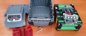
A screwdriver is one of the most versatile power tools. Many people have seen this from their own experience.
However, even such a wonderful tool has its drawbacks. One of them is the charger. If it breaks, it can be difficult to find one suitable for the model you need. And even if there is one, the price is high, and it’s easier to buy a new screwdriver. Another problem can be slow battery charging.
Many users decide to make their own charger. In this article you will learn what is needed for this and how to make such a device for 12 and 18 volts.
Charging a screwdriver without a charger
Restoring a battery without the help of a charger is not difficult, but many people have no idea how. You can charge the screwdriver battery without a charger using any constant voltage power supply. Its value should be equal to or slightly greater than the voltage of the battery being charged. For example, for a 12V battery, you can take a rectifier to charge a car. Using terminal clamps and wires, connect them to each other for about thirty minutes, observing the polarity, while monitoring the temperature of the battery.
You can also modify power devices with higher voltages using a simple integrated stabilizer. The LM317 chip allows you to control an input signal up to 40 volts. You will need two stabilizers: one is switched on according to the voltage stabilization circuit, and the second - on the current. This scheme can also be used when converting a charger that does not have charging process control units.
The scheme works quite simply. During operation, a voltage drop is formed across resistor R1; it is enough for the LED to light up. As it charges, the current in the circuit drops. After some time, the voltage on the stabilizer will be low and the LED will go out. Resistor Rx sets the highest current. Its power is selected to be at least 0.25 watts. When using this scheme, the battery will not be able to overheat, since the device automatically turns off when the battery is fully charged.
Originally posted 2018-04-06 09:06:40.
Conversion from a computer power supply
The AT power supply standard is suitable for conversion. The average output voltage is 14 V, and the average power does not exceed 400 W. These values are ideal for a 14V screwdriver power supply. You can take it from an old computer. The computer power supply comes with a built-in fuse and cooler. The main disadvantage is the dimensions of the PC component.
computer power supply
Power supplies for ATX standard computer system units are not suitable. They are more complex and creating a power supply for a screwdriver from them requires thorough knowledge of electronics. PSUs of the ATX standard require significant intervention in the design so that they can be built into a screwdriver. To remake an AT standard power supply, you should:
- Disassemble the computer system unit.
- Disconnect the power supplied by the green wire.
- Unsolder the black and green wires.
- Connect the black wire to black and the green wire to yellow.
- Solder one end of the green wires to the soldered black socket.
- Connect the second end of the green wire to the contacts of the screwdriver power supply.
If there is a red wire in the computer power supply, then it should be unsoldered. It is needed to control the load on the +5 V bus. Next, the incoming voltage is checked. If there is a value of 14 Volts, then the modified power supply is assembled. After this, the block is connected to the black and yellow wires. A screwdriver will be connected to it. When soldering, it is important to observe polarities. The black wire is on “-”, and the yellow wire is on “+”.
It is important to ensure that the power cord and wires do not get twisted during the remodeling process.
Types of chargers
This section describes typical electrical circuits. Select a suitable charger for a screwdriver taking into account the following factors:
- battery type;
- number of cells;
- possibility of careful control of the charging process;
- availability of skills and knowledge for high-quality assembly (adjustment) of a certain design;
- additional requirements for weight, dimensions, and other individual criteria.
Analog with built-in power supply
The popularity of such engineering solutions is explained by their comparative simplicity and low cost. The device shown in the following drawing provides stable voltage maintenance for charging a 12-volt unit with a sufficiently high current.
Analog charger
Explanations for the electrical diagram:
- the KR142EN microcircuit performs the main function - stabilization;
- for the example given (at 12V), the modification with the index “8B” in the designation is suitable;
- this element heats up, so it is mounted on a metal radiator with a dispersion area of 20-25 cm2;
- transformer windings (conductor cross-section) are calculated based on the required output current;
- capacitor C1 removes residual ripples after rectification by a diode bridge;
- The completion of the charging cycle is indicated by the extinguished LED (HL1), there is no automatic shutdown.
Analog with external power supply
The circuit diagram in this embodiment is similar to the considered example. The main difference is the separate design of the rectifier block:
- transformer;
- diode bridge;
- capacitor.
Electrical circuit of the charger control unit
Such a device can be made miniature. It can be connected to a standard, fairly powerful rectifier (this is a power supply for a laptop, tablet, or other equipment). Assembly instructions:
- the KT 818 transistor dissipates a lot of power, so it is installed on an efficient radiator (area from 35 to 45 sq. cm);
- using a tuning resistor, the optimal output current is adjusted taking into account the characteristics of the battery;
- as in the previous version, the end of the procedure is the LED going out.
Pulse
Previous devices are capable of restoring the functionality of a standard screwdriver battery in 4-6 hours. The scheme presented below will perform a similar task much faster (45 minutes - 1.5 hours). The main advantages are minimal size and lightness.
Pulse memory
This circuit is designed to charge advanced Ni-Cd batteries. They are equipped with a special contact, which is necessary for monitoring temperature indicators. Such a device reproduces the accelerated discharge cycle without additional commands. The user can set various combinations of output parameters using jumpers.
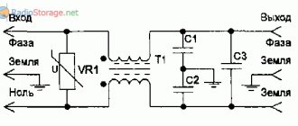
Typical power supply diagram for a screwdriver
The power supply consists of a power transformer, a capacitor and a rectifier. The presented circuit for powering a screwdriver from a network with a rated voltage of 220V is designed for 12-volt devices.
Circuit example
Transformers in a typical circuit are selected with a power of 300 W or more. The second winding has a voltage varying around 20-24V. The current strength should not be less than 15A. Diode bridges also depend on the voltage of winding II. The capacitor located at the output must have a capacity of at least 470 μF, and the input voltage must be at least 25V. The elements are installed in a board tightly fixed in a housing of the required size. After this, the screwdriver is connected to a 220V electrical network and checked with a multimeter to ensure that all parameters are met.
How to make a charger for a screwdriver
First, the general parameters of the project are clarified. The existing unit is used as a basis, which ensures that the battery is fixed in the correct position and reliable electrical contact. Specify the type of battery and the corresponding charger.
Diagram and order of assembly of the power supply
Analog circuits are simpler, but take up a lot of space. Pulse devices are compact and highly complex. Having chosen the appropriate option, they use wall mounting or create a printed circuit board taking into account the free space in the case. During manufacturing, ventilation holes are created to effectively cool powerful transistors and microcircuits. At the final stage, functionality is checked and assembly is completed.
How to use an electrical appliance
The charger is used taking into account a certain circuit design. The simplest models only signal the completion of the process, but do not turn off the mains power. Some types of batteries must be charged with careful temperature control. After a practical study of the assembly process, it will not be difficult to repair a failed product.
What tools and materials are needed for manufacturing
People who understand electrics recommend placing the power supply inside the screwdriver in place of the battery. This will protect it from moisture, dust and dirt, and the tool itself will last longer.
Note! To open the battery case, you can use a regular knife, running it along the seam.
In addition, you may need the following tools:
- knife;
- soldering iron;
- insulating tape.
Important! The list of materials depends entirely on what kind of power supply needs to be made and what circuit is used initially. You can work with car units, or you can simply take a power supply from a computer, but this option will be more cumbersome.
Preparing tools for connecting a homemade uninterruptible power supply
Homemade charging devices
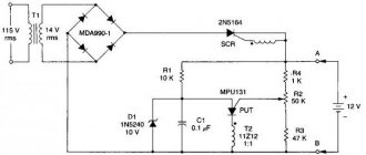
It’s quite simple to make a charger for a 12-volt screwdriver yourself, by analogy with the one used in the Interskol charger. To do this, you will need to take advantage of the ability of the thermal relay to break the contact when a certain temperature is reached.
In the circuit, R1 and VD2 represent a sensor for the flow of charge current, R1 is designed to protect the diode VD2. When voltage is applied, transistor VT1 opens, current passes through it and LED LH1 begins to glow. The voltage drops across the chain R1, D1 and is applied to the battery. The charging current passes through the thermal relay. As soon as the temperature of the battery to which the thermal relay is connected exceeds the permissible value, it is triggered. The relay contacts switch and the charging current begins to flow through resistance R4, the LED LH2 lights up, indicating the end of the charge.
Circuit with two transistors
Another simple device can be made using available elements. This circuit operates on two transistors KT829 and KT361.
The amount of charge current is controlled by the KT361 transistor to the collector to which the LED is connected. This transistor also controls the state of the KT829 component. As soon as the battery capacity begins to increase, the charging current decreases and the LED gradually goes out accordingly. Resistance R1 sets the maximum current.
The moment the battery is fully charged is determined by the required voltage on it. The required value is set with a 10 kOhm variable resistor. To check it, you will need to place a voltmeter on the battery connection terminals, without connecting the battery itself. Any rectifier unit designed for a current of at least one ampere is used as a constant voltage source.
Using a custom chip
Manufacturers of screwdrivers are trying to reduce prices for their products, often this is achieved by simplifying the charger circuit. But such actions lead to rapid failure of the battery itself. By using a universal chip designed specifically for the MAXIM MAX713 charger, you can achieve good charging performance. This is what the charger circuit for an 18-volt screwdriver looks like:
The MAX713 chip allows you to charge nickel-cadmium and nickel-metal hydride batteries in fast charge mode, with a current of up to 4 C. It can monitor battery parameters and, if necessary, reduce the current automatically. Once charging is complete, the IC-based circuit draws virtually no power from the battery. It can interrupt its operation due to time or when the temperature sensor is triggered.
HL1 is used to indicate power, and HL2 is used to display fast charge. The setup of the circuit is as follows. To begin with, the charging current is selected, usually its value is equal to 0.5 C, where C is the battery capacity in ampere hours. The PGM1 pin is connected to the positive supply voltage (+U). The power of the output transistor is calculated using the formula P=(Uin - Ubat)*Icharge, where:
- Uin – highest voltage at the input;
- Ubat – battery voltage;
- Icharge – charging current.
Resistance R1 and R6 is calculated using the formulas: R1=(Uin-5)/5, R6=0.25/Icharge. The choice of time after which the charging current turns off is determined by connecting the PGM2 and PGM3 contacts to different terminals. So, for 22 minutes PGM2 is left unconnected, and PGM3 is connected to +U, for 90 minutes PGM3 is switched to the 16th leg of the REF chip. When it is necessary to increase the charging time to 180 minutes, PGM3 is short-circuited with the 12th leg of the MAX713. The longest time of 264 minutes is achieved by connecting PGM2 to the second leg, and PGM3 to the 12th leg of the microcircuit.
General circuit and current consumption of 12, 14 and 18V screwdrivers
Block diagram of a screwdriver.
Screwdrivers from different manufacturers are built on different element bases, but the structural electrical circuit for all is approximately the same. The power tool consists of:
- removable battery;
- control boards;
- trigger switch combined with speed controller;
- frequency control range switch (may be missing);
- electric motor (commutator or brushless).
When making your own power source for a screwdriver, you need to pay attention to two parameters:
- voltage;
- rated output current.
With voltage, everything is simple - the new power source must have an output voltage equal to the rated supply voltage of the power tool . A decrease leads to a loss of torque, an increase leads to a decrease in resource. Operation of the control board at low voltage is not guaranteed; at high voltage, it is likely to fail.
The required operating current is more difficult to determine. Manufacturers of power tools rarely indicate current consumption. A little more often they indicate power in watts. But on the nameplates of screwdrivers you can find the following data:
- operating voltage (in volts);
- rotation speed (in revolutions per minute);
- torque (in newtons per meter).
These data seem sufficient to calculate the operating current.
Label with electrical characteristics of the DEKO DKCD20FU screwdriver.
In fact, not everything is so rosy. If you use data from a real screwdriver and try to calculate the rated current, you will get an absurd result.
First, the output power is calculated using the formula:
P=T*RPM/9550 , where:
- P – power, kW;
- T – torque, N/m;
- RPM – rotation speed, rpm;
- 9550 – a coefficient combining the conversion from one unit to another.
For the given data it turns out:
P=42*1350/9550=5.9 kW.
This developed power must be divided by the efficiency (approximately equal to 0.8), resulting in a power consumption of about 7 kW. At a voltage of 20 volts, the batteries must deliver a current of 350 A!!! With a capacity of 2 Ah, the battery will be discharged in 20 seconds (even if theoretically the battery provides such a current). This is the promised absurdity. The reason for this may be crafty declarations of revolutions or torque. Perhaps the greatest torque is produced only at a certain speed, but even if you know it, there will be little practical sense. After all, a screwdriver operates at different frequencies.
Therefore, you need to focus on the following figures obtained experimentally:
- idle speed – 1..2 amperes;
- average load – 4..6 A;
- maximum load – 8..11 A;
- current surges during full braking – up to 30 A.
You can clarify these figures for a specific screwdriver by measuring the actual current consumption in different modes, putting together a simple circuit for this, and driving the power tool under different loads.
Circuit for measuring current consumption.
Or you can not specify, but focus on the numbers indicated above. A power supply will be needed for a maximum current of 10 A (but not less than 5..6), preferably with overcurrent protection.
Types of batteries
A charger for a screwdriver is created taking into account the features of an autonomous power source. The following sections discuss popular rechargeable batteries
When studying the compatibility of functional components of a screwdriver, it is recommended to pay special attention to charge recovery modes
Nickel-cadmium
These batteries are different:
- reasonable cost;
- good energy indicators;
- long service life.
Unfortunately, big problems arise at the disposal stage. Harmful chemical compounds in Ni-Cd batteries cause great harm to the environment. For this reason, the use of such products is gradually being phased out in many countries.
If other data is not indicated by the manufacturer, select the operating mode along with a suitable electrical circuit diagram for the screwdriver according to the following data:
- to extend service life, it is recommended to “train” with 2-6 full work cycles before starting operation and subsequently every 6-8 months;
- long-term storage in a discharged state is permissible;
- pre-discharge voltage – from 0.9 to 1 V;
- the nominal capacity is maintained only at positive temperatures;
- overheating is unacceptable during the recovery process (not higher than +40°C);
- the completion of the cycle is indicated by a slight decrease in voltage;
- The charge current is calculated using the formula:
2*C.
Important! The letter “C” denotes the capacity indicated in the battery passport. If C=2.5 A*h, you can use a charge with a current of 5A = 2*2.5
Sulfuric acid batteries for screwdrivers
Products in this category are created on the basis of lead cells with an acid-type gel electrolyte. Advantages:
- simplicity;
- reasonable price;
- Possibility of use in any position.
The main disadvantages of sulfuric acid batteries are their significant dimensions and heavy weight. The cells are charged with a voltage of 1.8-2 V while maintaining a current of 0.1-0.15 * C.
Li-ion batteries for screwdriver
This is the most common modern solution. Batteries of a similar design are used in smartphones and laptops, and other household and professional equipment. Pros:
- better performance compared to the analogues discussed above in terms of energy storage per unit volume (weight);
- wide operating temperature range;
- long-term preservation of good operating parameters;
- no excessive recycling requirements.
One standard cell is charged with a voltage of 3.6V to a level of 4.2V. Exceeding the threshold set by the manufacturer will shorten the service life. A low level limits savings capabilities. The energy potential of batteries is restored with careful temperature control.
Revitalizing a nickel-cadmium battery
Screwdrivers equipped with nickel-cadmium batteries are practically a thing of the past. But they are still sold, found and even work, since Ni-Cd cells can “live” up to 20-25 years, although they can withstand about 900 charge/discharge cycles. Another feature of nickel-cadmium batteries is that they can be stored in a discharged state. So if you find your grandfather’s screwdriver with a Ni-Cd battery in the attic, then it makes sense to try to revive it.
Let's try to charge the battery. Any charger capable of providing the required voltage and current equal to half the battery capacity will do.
For Ni-Cd cells this charging current is normal. They can easily withstand a current equal to their capacity, and even twice as much.
We turn it on and try to charge it. If the battery takes charge, then we continue. If not and there is a hollow zero on it, we move on to plan “G” and “P” (see below).
As soon as the voltage on the battery reaches 1.37 V, multiplied by the number of batteries, we stop the process. But that's not all. It is not a fact that the battery is fully charged. Nickel-cadmium batteries suffer from the so-called memory effect. If they were constantly discharged, say, to 60%, and then put on charge, then they will get used to it and will continue to refuse to work when discharged to the same 60%. Therefore, we discharge our battery with approximately the same current as we charged it. We discharge to a value of 1 V, multiplied by the number of batteries. You can use car lamps or the screwdriver itself as a load.
After that, fully charge again. We repeat the “charge/discharge” operation 3-4 times. We fully charge and try to use a screwdriver. If even after all these manipulations the battery capacity is significantly lower than declared, then, unfortunately, we have on our hands a decrepit, outdated old man. He cannot be resuscitated.
Plan "Zh", push
Plan “G” is to “push” the battery with short (0.2-0.3 sec) high current pulses. Moreover, the current should be much (tens of times) greater than the battery capacity. It is better to “push” each battery separately. Therefore, we open the battery and find out where each battery has a plus and a minus. We will use a car battery as a pusher, but any other powerful source with a voltage of 10-15 V will do.
We connect the minus of our element to the minus of the “pusher”, connect one end of the wire to the plus of the “pusher”, and with the other end we briefly touch the positive terminal of the Ni-Cd element. The frequency of touches is 2-3 per second. As a result of such burning, the dendrites that caused microcircuits are eliminated, and the battery comes to life.
While touching, make sure that the wire does not weld to the battery terminal. In general, it is better to touch not with the wire, but, say, with the head of the screw on which the wire is screwed. And don't forget about safety glasses!
The operation is carried out within 5-6 seconds. We put it on charge. If the process has started, we eliminate the memory effect (see above). Let's try to use it.
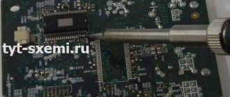
Operating principle of the charger
If a memory device fails, it makes sense to first try to restore it. To carry out repairs, it is advisable to have a charger circuit and a multimeter. The circuitry of many charging devices is based on the HCF4060BE microcircuit. Its switching circuit forms the delay of the charging time interval. It includes a crystal oscillator circuit and a 14-bit binary counter, making it easy to implement a timer.
The operating principle of the charger circuit is easier to understand using a real example. This is what it looks like in an Interskol screwdriver:
This circuit is designed to charge 14.4-volt batteries. It has an LED indication showing the connection to the network, LED2 is lit, and the charging process, LED1 is lit. The U1 HCF4060BE chip or its analogs: TC4060, CD4060 are used as a counter. The rectifier is assembled on power diodes VD1-VD4 type 1N5408. PNP transistor type Q1 operates in key mode; the control contacts of relay S3-12A are connected to its outputs. The operation of the key is controlled by controller U1.
When the charger is turned on, the alternating voltage of 220 volts is supplied through a fuse to a step-down transformer, at the output of which its value is 18 volts. Then, passing through the diode bridge, it is straightened and falls on a smoothing capacitor C1 with a capacity of 330 μF. The voltage across it is 24 volts. When connecting the battery, the relay contact group is in the open position. The U1 microcircuit is powered through a zener diode VD6 with a constant signal of 12 volts.
The SK1 button used works without fixing. When it is released, all power is supplied through the chain VD7, VD6 and limiting resistance R6. And also power is supplied to LED1 through resistor R1. The LED lights up, signaling that the charging process has begun. The operating time of the U1 chip is set to one hour of operation, after which power is removed from the transistor Q1 and, accordingly, from the relay. Its contact group breaks and the charging current disappears. LED1 goes out.
This charger is equipped with an overheat protection circuit. Such protection is implemented using a temperature sensor - thermocouple SA1. If during the process the temperature reaches more than 45 degrees Celsius, the thermocouple will work, the microcircuit will receive a signal and the charging circuit will be broken. After the process is completed, the voltage at the battery terminals reaches 16.8 volts.
This charging method is not considered intelligent; the charger cannot determine the state of the battery. Because of this, the battery life of the screwdriver will decrease due to the development of its memory effect. That is, the battery capacity decreases each time it is charged.
Benefits of cordless tools
The main advantage of power tools in this category is autonomy. The built-in rechargeable battery ensures the functionality of the equipment without connecting to a stationary power supply of 220 or 380V. This feature is used to carry out repairs in new buildings, in “camping” and other difficult conditions.
Other benefits:
- Without the interfering power supply cable, it is easier to carry out individual operations;
- Low battery voltage reduces the risk of electric shock;
- This tool is much quieter compared to an alternative autonomy solution based on a gasoline generator.
For your information. To be fair, it should be noted that adding a battery adds weight, cost and complexity.
Charge modes
Nickel-cadmium (sulfuric acid) cells are charged with a voltage of 1.2 (1.8-2) V, respectively, while maintaining a current of (0.1-0.15) * C. In lithium-ion models, the voltage is increased to 3.3 V A standard 18 volt screwdriver charger maintains the same level during charging. The end of the operation is controlled at level 21 V.
Important! Lithium cells are especially sensitive to overheating. A temperature increase of more than +60°C can cause not only structural destruction, but also fire
To eliminate dangerous situations, this parameter is carefully monitored.
Tags: machine, ampere, beat, sconce, type, harm, generator, , capacity, clamp, like, capacitor, , installation, power, multimeter, voltage, nominal, limiter, connection, polarity, potential, wire, project, manufacturer , start, , work, size, resistor, relay, repair, row, light, LED, network, connection, resistance, term, stabilizer, zener diode, circuit, ten, type, current, transistor, transformer, , shield, power tool, effect
How long does it take to fully charge
How long does it take to charge a screwdriver battery? It is necessary to clarify for what purpose it is being charged. Manufacturers are looking to speed up charging times to reduce interruptions and improve competitiveness. Therefore, the maximum permissible charging current values are set. It is common to sacrifice 10-20% of the charge capacity at the end of the charging cycle.
This can be seen on the lithium battery charge graph. Where in the first hour of charging 70% of the capacity is collected, in the second hour - another 20%, which is already 90%, and it takes another 1 hour to collect the last 10%, for a total of 3 hours. And a standard Bosch charger from China charges a lithium battery in just 30 minutes. Taking these subtleties into account, we can now answer the question asked.
To operate the tool, you only need to charge the battery once. If necessary, you don’t have to wait for the charging time to end, and start working after half the standard charging time. Undercharging of batteries in isolated cases does not have negative consequences.
To carry out training cycles, maximum battery charging is required, and even more so to restore its capacity. How to do this on a standard charger if it automatically turns off? After the voltage has stabilized, after 20–30 minutes you can again continue charging the battery on a standard device. He will take on more energy. The charge cycle should be carried out up to three times. This way the battery will be charged almost 100%. It is important that the entire electrolyte volume is used in the subsequent shock training cycle.
New Ni-Cd and Ni-MH cells are charged on a standard device from 1 to 8 hours, according to the data sheets of different manufacturers. This variation in time is caused by different settings of the charging current value, depending on the manufacturer’s position on this issue. In addition, chargers from even the same manufacturer can have a spread of up to 2 hours due to settings errors, because at the final stage of charging the current decreases extremely slowly. And there will always be a minimum current.
Expert opinion
Alexey Bartosh
Specialist in repair and maintenance of electrical equipment and industrial electronics.
Ask a Question
Advice! During long-term operation of the screwdriver, the actual capacity decreases. It is useful to measure the charging time of new batteries after training cycles and record them on the case. By comparing with the subsequent charging time after a year or two, you can understand how much capacity the battery has lost.
New lithium (Li) batteries take anywhere from 30 minutes to 120 minutes to charge. This also depends on each manufacturer's charger settings.