AC current means alternating electric current. The name is associated with the peculiarity of its flow in the electrical circuit. It is characterized by a change in direction of movement, magnitude - all characteristics opposite to constant voltage (AD).
Direction of movement of alternating current to the outlet Source imgsmail.ru
What is electricity
The appearance of electricity is a certain set of phenomena that are caused by the existence of electric charges with the “+” and “-” signs, their interaction with each other and the possibility of movement. Due to the fact that a set of charges can move along a conductor and have attractive and repulsive properties, the phenomenon of magnetism and electricity was discovered. Thales was one of the first to describe this, and later in 1600, the English physicist William Gilbert. Over time, knowledge about this phenomenon has only increased and progressed.
Types of current and their graphs relative to time
From the point of view of physics, electricity is the ordered movement of positively and negatively charged particles through a conductor-type material under the influence of an electric field. The particles are ions, protons, neutrons and electrons.
Directed particle movement
Sign and color marking of AP elements
In accordance with the requirements of GOST R 50462, conductors and buses of electrical networks with a grounded neutral must be marked “PE” with the addition of a dashed line of alternating yellow and green stripes at the end sections of the route. At the same time, the tires of the working “zero” are indicated in blue and marked as “N”.
In those circuits where neutral working conductors are used as a protective grounding element with a connection to a grounding device, blue color is used when designating them.
At the same time, they are labeled “PEN” and alternating yellow and green strokes are added to the end sections of the schematic symbols.
It should be noted that strict compliance with all provisions and requirements of GOST and PUE will allow the consumer to organize the safe operation of the equipment at his disposal.
What is alternating (AC) and direct (DC) current?
AC from English “alternating current” means alternating current, and DC “direct current” means direct current.
AC alternates the direction of current, but DC flows in only one direction.
Welding machines and electrodes marked DC have a constant polarity, while those marked AC change polarity 120 times per second with a current frequency of 60 hertz.
Decoding the symbols 20k and 20m on a multimeter
Next to the numbers indicating the measurement range, you can see letters such as µ, m, k, M. These are so-called prefixes, which indicate the multiplicity and fractionality of units of measurement.
- 1µ (micro) – (1*10-6 = 0.000001 from unit);
- 1m (millies) – (1*10-3 = 0.001 from unit);
- 1k (kilo) – (1*103 = 1000 units);
- 1M (mega) – (1*106 = 1,000,000 units);
For example, to check the same heating elements, it is better to take a tester with a megometer function. I had a case where a malfunction of the heating element in a dishwasher was detected only by this function. For radio amateurs, of course, more complex devices are suitable - with the function of measuring frequencies, capacitor capacity, and so on. Nowadays there is a very large selection of these devices; the Chinese don’t do anything.
{SOURCE}
Origin of alternating and direct current
A magnetic field near a wire causes electrons to flow in one direction along the wire because they are repelled by the negative side of the magnet and attracted to the positive side. Thus, the battery-powered DC power source was born, primarily thanks to the work of Thomas Edison.
Alternators gradually replaced Edison's DC battery system because alternating current is safer to carry over longer distances around town and can provide more power. Instead of constantly applying magnetism along a wire, scientist Nikola Tesla used a rotating magnet. When the magnet was oriented in one direction, electrons flowed toward the positive, but when the magnet's orientation was reversed, the electrons also turned.
comparison table
Comparison chart of AC and DC
Alternating current Direct currentAmount of energy that can be carried Cause of direction of electron flow frequency direction Current Electron flow Derived from Passive Parameters Force Factor Types
| Safe to carry long distances around town and can provide more power. | DC voltage cannot travel very far before it begins to lose energy. |
| A rotating magnet along a wire. | Stable magnetism along the wire. |
| The AC frequency is 50Hz or 60Hz depending on the country. | The DC frequency is zero. |
| It changes direction as it flows in a circle. | It flows in one direction in the circuit. |
| This is a quantity that changes over time | This is a constant current. |
| The electrons continue to switch directions - forward and backward. | Electrons move steadily in one direction or "forward". |
| Alternator and network. | Cell or battery. |
| Resistance. | Only resistance |
| Lies between 0 and 1. | it's always 1. |
| Sine, Trapezoidal, Triangular, Square. | Clean and pulsating. |
Alternating and direct current. The horizontal axis is time and the vertical axis represents voltage.
D.C
The international symbol for this DC voltage is Direct Current (direct current), and the symbol on electrical diagrams is “—” or “=”. The magnitude and polarity of this type of voltage are unchanged, and the current strength changes only when the load changes. This type of electric current is produced by batteries, batteries and elements of solar power plants.
The engines of trams, trolleybuses and other electric vehicles operate from the DC network. These electric motors have better traction characteristics than AC motors.
Information! Most electronic circuits operate on DC voltage, but they are powered by AC power through a built-in or external power supply with a rectifier.
Alternating current
The international designation for this AC voltage is Alternating Current, and the symbol on electrical diagrams is “~” or “≈”.
The magnitude and polarity of alternating current in the network changes all the time. The frequency of these changes is 50Hz in Europe and some other countries and 60Hz in the USA. Most household and industrial electrical appliances are manufactured to be powered by alternating voltage.
Almost all electricity used in everyday life and industry is variable. For transmission over long distances, it is increased using transformers, and at the end point of the line it is reduced to the required value. This allows you to reduce the cost of power lines and losses. In order to eliminate voltage fluctuations, stabilizers are installed for critical devices.
With increasing voltage and constant transmitted power, the current strength and cross-section of the wires decrease proportionally. If the voltage is not increased, then large cross-section cables must be used to supply electricity to the consumer, and transmission over long distances will be impossible. That's why the outlet has AC current.
There are two contacts in a home socket - phase and neutral. In some cases, a grounding cable is added to them. This single-phase voltage is part of a three-phase system. It includes three identical networks. The voltage in these networks is phase shifted by 120° relative to each other.
At first this system was six-wire. Nikola Tesla invented it in this form. Later, M. O. Dolivo-Dobrovolsky improved this scheme and proposed transmitting three-phase voltage over three or four wires (L1, L2, L3, N). He also showed the advantages of a three-phase power supply system over schemes with a different number of phases.
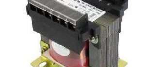
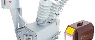
Transformer device
In accordance with GOST 16110 −82, the definition of a transformer is as follows: a transformer is an electromagnetic device of a static type, which is equipped with two or more inductively coupled windings and is designed to convert one or more alternating current systems into one or more other systems.
This electromagnetic product has a simple design consisting of the following elements: magnetic core (magnetic system), windings, winding frames, insulation (not in all transformers), cooling system. additional elements. In practice, manufacturers use one of three basic concepts to produce transformers:
- Rod. The windings are wound on the outermost rods.
- Armored. The side walls remain without windings.
- Toroidal. It has a ring shape with uniform winding around the entire circumference.
Magnetic system
Magnetic cores for a transformer have a certain geometric shape and are made from a number of materials, which include electrical steel, permalloy, ferrite or other material with ferromagnetic properties. Depending on the material and design, the magnetic circuit can be assembled from plates, pressed, wound from a thin tape, or assembled from two, four or more “horseshoes”.
The rods act as a frame for placing the main windings. They can have different spatial arrangements, depending on which several types of systems are distinguished.
- A flat magnetic system with the longitudinal axes of rods and yokes located in the same plane.
- A spatial system where the longitudinal axes of the rods are located in different planes.
- A symmetrical system equipped with identical rods that have the same relative position in relation to the yokes.
- An asymmetrical system consisting of rods, some of which may differ in shape, design and size, with different relative positions in relation to the yokes.
Winding design
The winding is the main element of the transformer. It is a multi-turn structure made of one or more copper (less often aluminum) wires of various diameters. As a rule, power transformers use conductors with a square cross-section, which allows more efficient use of available space, thereby increasing the fill factor (K).
To prevent short circuits, each winding is insulated. Special paper or enamel varnish can be used as an insulating material. By the way, if two separately insulated and parallel-connected wires were used to make the winding, then they can be equipped with a common paper insulation.
Fuel tank
The tank is one of the most important additional elements of the transformer. It is a container designed to store transformer oil, as well as provide physical protection to the active component. In addition, the tank body is designed for mounting auxiliary equipment and a control device.
One of the internal elements of the tank is a high-current resonator. It is subject to rapid and frequent overheating when the rated power and transformer currents increase. To reduce the risk of overheating, inserts made of non-magnetic materials are installed around the resonators.
The internal coating of the tank is made of conductive shields that do not allow magnetic fluxes to pass through the walls of the tank. Sometimes there is a coating that is made of a material with low magnetic resistance. This coating option absorbs internal flows before approaching the walls of the tank.
Electrical voltage is divided into two types:
- constant (dc)
- variable (ac)
The designation for direct current is (—), for alternating current the designation is (~). The abbreviations ac and dc are well-established and are used along with the names “constant” and “variable”. Now let's look at what is their difference. The fact is that constant voltage flows only in one direction, which is where its name comes from. And a variable, as you already understood, can change its direction. In particular cases, the direction of the variable may remain the same. But, in addition to the direction, its magnitude can also change. In a constant, neither magnitude nor direction changes. The instantaneous value of alternating current is its magnitude, which is taken at a given moment in time.
In Europe and Russia, the accepted frequency is 50 Hz, that is, it changes its direction 50 times per second, while in the USA, the frequency is 60 Hz. Therefore, equipment purchased in the United States and in other countries may burn out with different frequencies. Therefore, when choosing equipment and electrical appliances, you should carefully ensure that the frequency is 50 Hz. The higher the frequency of the current, the greater its resistance. You can also notice that in the sockets in our house it is AC that flows.
In addition, alternating electric current is divided into two more types:
- single-phase
- three-phase
For single-phase, a conductor is required that will conduct voltage and a return conductor. And if we consider a three-phase current generator, it produces an alternating voltage with a frequency of 50 Hz on all three windings. A three-phase system is nothing more than three single-phase electrical circuits, out of phase relative to each other at an angle of 120 degrees. Through its use, it is possible to simultaneously provide energy to three independent networks, using only six wires that are needed for all conductors: forward and reverse, to conduct voltage.
And if you, for example, have only 4 wires, then there will be no problems either. You will only need to connect the return conductors. By combining them, you get a conductor called neutral. It is usually grounded. And the remaining external conductors are briefly designated as L1, L2 and L3.
But there is also a two-phase one, it is a complex of two single-phase currents, in which there is also a direct conductor for conducting voltage and a reverse one, they are shifted in phase relative to each other by 90 degrees.
How is resistance indicated on multimeters?
One of the main measurements taken by a multimeter is resistance. It is designated by a horseshoe symbol: Ω, Greek omega. If there is only such an icon on the multimeter body, the device measures the resistance automatically. But more often there is a range of numbers nearby: 200, 2000, 20k, 200k, 2000k. The letter " k " after the number denotes the prefix "kilo", which in the SI corresponds to the number 1000.
What is the designation for direct and alternating voltage?
Direct voltage or current is abbreviated DC, which stands for Direct current. On diagrams and electrical devices, it is also customary to indicate constant voltage with a simple straight line (—).
The alternating voltage icon is written in the form of a slightly different abbreviation ( – AC. If you decipher it, you get “Alternating current”. On the terminals of electrical appliances and switchboards, as well as on diagrams, it can be depicted as a wavy line (
Important! If the network is designed to carry both types of electricity, it is marked as “AC/DC” and is indicated on the diagram by a double line (the upper line is straight and solid, and the lower line is straight and dotted).
Designations on diagrams and devices
It is generally accepted that the direction of electricity goes from a contact with a plus sign to a contact with a minus sign.
Places with high potentials are called “positive pole” and are indicated by a + (plus) sign. Points with lower potentials, accordingly, are called the “negative pole” and are designated by the sign - (minus).
Initially, it was accepted that the electrical insulation of positive wires is red, while wires with a minus sign are painted blue or black.
Symbols on electrical appliances: - or =. Unidirectional electricity (including constant electricity) is denoted by the Latin alphabet DC, or the Unicode symbol is used - U+2393.
The abbreviations AC and DC are firmly rooted in everyday use and are used along with the usual names “variable” and “constant”:
- designation of direct voltage (—) or DC (Direct Current);
- AC sign (
) or AC (Alternating Current) - designation of alternating current.
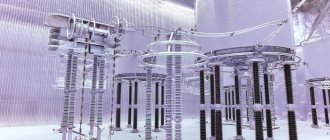
Sources of electrical energy
World electricity production is based on the operation of power plants. The basic principle of operation of the stations is that the turbines of the electric generators installed in them rotate using other types of energy. They got their name according to the type of energy used:
- thermal (TPP) – organic fuels are used as raw materials: coal, gas, fuel oil and others;
- hydroelectric power plants (HPP) - turbine blades are rotated by falling water, which is also used to cool the working surfaces of generators;
- nuclear power plants (NPPs) are one of the types of thermal power plants, where heat released as a result of a nuclear reaction is used to produce steam that rotates a turbine.
AC generator
The placement of certain types of power plants depends on the regional distribution of raw materials, the geographical location of rivers and the selection of suitable sites for the construction of nuclear power plants.
Attention! The main share of world electricity production is still taken by thermal power plants. The dangers during the operation of nuclear power plants are still a limiting factor for a complete transition to this powerful type of electricity production.
The uneven population density on the planet does not allow such energy sources to be brought as close as possible to places of consumption. Therefore, it is necessary to transmit the generated electricity over long distances. Since both consumption and receipt of energy occur in real mode, energy systems have been created that connect power plants with each other. In addition, the systems themselves are organized into more powerful energy systems. This was done to create a reserve of operating power and the ability to regulate the supply of electricity to consumers in an uninterrupted manner.
The difference in time zones, seasonal fluctuations in consumption - all this loads some stations and underloads others. Power grids allow stations to feed each other in case of overload.
In addition to traditional power plants, alternative sources have proven themselves: wind generators and solar panels. With their help, they solve problems of providing power to consumers in individual cases.
As for direct current sources, they can be divided into two types:
- chemical - galvanic cells that use oxidation reactions, and electrolytic cells that generate energy through electrolysis;
- electromechanical - direct current generators that convert rotational energy into its electrical form.
Galvanic cells (batteries) have a finite service life. They are designed so that after the oxidation reaction is completed, the generation of electricity stops. Electrolytic cells (batteries) have a periodic operating mode. After discharge, they can be charged by applying a charge current to their poles and used again.
Electricity sources
Edison's ideas
Modern life cannot be imagined without electricity. In order for it to serve civil and industrial purposes, it must not only be produced, but also delivered to the consumer. The first who decided to produce electricity in large quantities and transport it to factories, offices and households was the American entrepreneur Thomas Edison, one of the most influential inventors in the world.
To implement his idea, he designed and tested DC steam generators, electricity meters and distribution network elements. Carrying out the first electrification of lighting was not easy at that time. The owners of gas companies viewed Edison as a dangerous competitor who could jeopardize the existence of their enterprises. But nothing could stop the inventor. Neither the colossal cost of laying cables in the sidewalks, nor accidents during testing prevented him from launching the first lighting network of five thousand lamps in September 1882.
https://youtube.com/watch?v=dwaSF3W4TxU
After 5 years, more than 50 Edison power plants were already operating. Despite his great success, the inventor was unable to expand the geography of his electrical networks throughout the world. Residents of the areas where the power plants were located complained about smoke and soot, and forced the closure of Edison's production facilities. Thus, the first generation of coal-fired power plants eventually ceased operation, giving way to thousands of new ones generating AC.
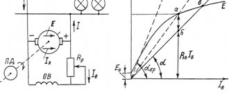
Electromotive force and electrical voltage [edit | edit code ]
The potential difference between points between which direct current flows can be characterized by electromotive force and electric voltage.
Electromotive force
Each primary source of electrical energy creates an external electric field. In electrical machines (DC generators), an extraneous electric field is created in the metal conductors of the armature rotating in a magnetic field, and in galvanic cells and batteries - at the point of contact of the electrodes with the electrolyte (solutions of salts or acids) during their chemical interaction.
An external electric field present in a direct current source of electrical energy continuously interacts with the electric charges of conductors forming a closed circuit with it, and creates a constant electric current in it.
By moving electric charges along a closed circuit, the forces of an external electric field overcome the resistance of opposing forces, for example, material particles of conductors. This leads to the fact that the forces of an external electric field do work due to the energy of this field. As energy is consumed, the external electric field replenishes it with mechanical or chemical energy.
As a result of the work of the forces of an external electric field, the energy of this field is transformed in an electrical circuit into some other types of energy, for example, into thermal energy in metal conductors, thermal and chemical energy in electrolytes, thermal and light energy in electric lamps, and so on.
For the sake of brevity, the expression “work of external electric field forces” of a source of electrical energy is usually replaced by the expression “work of a source of electrical energy.”
If the work done by a source of electrical energy when moving a single electric charge throughout a closed electrical circuit is known, then it is easy to determine the work done by it when transferring a certain electric charge Q{displaystyle Q} along this circuit, since the amount of work is proportional to the amount of charge.
A quantity numerically equal to the work done by a source of electrical energy when transferring a unit of positive charge throughout a closed circuit is called electromotive force E{displaystyle E}.
Consequently, if a source of electrical energy, when transferring charge Q{displaystyle Q} throughout a closed circuit, has done work A{displaystyle A}, then its electromotive force E{displaystyle E}
is equal to E=AQ{displaystyle E={frac {A}{Q}}} .
In the SIM International System of Units (the unit of measurement of electromotive force is one volt (v, V){displaystyle (~v,~V~)}. The unit is named after the Italian physicist and physiologist Alessandro Volta.
The electromotive force of a source of electrical energy is equal to one volt if, when moving one coulomb of electricity throughout a closed circuit, it performed work equal to one joule:
1 volt=1 joule1 coulomb{displaystyle 1~volt={frac {1~joule}{1~coulomb}}} .
For example, if the electromotive force of any source of electrical energy is E=220 volt{displaystyle E=220~volt}, then this must be understood in such a way that the source of electrical energy, moving one coulomb of electricity throughout the closed circuit, will do work A=220 joule {displaystyle A=220~joule} , since E=AQ=220 joule1 coulomb{displaystyle E={frac {A}{Q}}={frac {220~joule}{1~coulomb}}} .
From the formula E=AQ{displaystyle E={frac {A}{Q}}} it follows that A=EQ{displaystyle A=EQ} , that is, the work of an electrical energy source when transferring its electric charge throughout a closed circuit is equal to the product of the electromotive force E {displaystyle E} it by the amount of transferred electric chargeQ{displaystyle Q} .
Electrical voltage
If a source of electrical energy transfers electric charge Q{displaystyle Q} throughout a closed circuit, then it does some work A{displaystyle A} . It performs part of this work A0{displaystyle A_{0}} when transferring charge Q{displaystyle Q} along the internal section of the circuit (a section inside the source of electrical energy itself), and the other part A1{displaystyle A_{1}} when transferring charge Q {displaystyle Q} along the external part of the circuit (outside the source).
Therefore, A=A0+A1{displaystyle A=A_{0}+A_{1}} , that is, the work A{displaystyle A} performed by a source of electrical energy when transferring electric charge Q{displaystyle Q} throughout the entire closed circuit is equal to the amount of work performed by it when transferring this charge along the internal and external sections of this circuit.
If we divide the left and right sides of the equality A=A0+A1{displaystyle A=A_{0}+A_{1}} by the unit charge Q{displaystyle Q} , we get the work per unit charge: AQ=A0Q+A1Q{ displaystyle {frac {A}{Q}}={frac {A_{0}}{Q}}+{frac {A_{1}}{Q}}} .
The work done by a source of electrical energy when transferring a single charge throughout a closed circuit is numerically equal to its electromotive force, that is, E=AQ{displaystyle E={frac {A}{Q}}} , where E{displaystyle E} is the electromotive force power source of electrical energy.
The quantity A0Q{displaystyle {frac {A_{0}}{Q}}} , numerically equal to the work done by a source of electrical energy when transferring a unit charge along the internal section of the circuit, is called the voltage drop (voltage) on the internal section of the circuit, that is, U0= A0Q{displaystyle U_{0}={frac {A_{0}}{Q}}} , where U0{displaystyle U_{0}} is the voltage drop in the internal section of the circuit.
The quantity A1Q{displaystyle {frac {A_{1}}{Q}}} , numerically equal to the work done by a source of electrical energy when transferring a unit charge Q{displaystyle Q} along the external section of the circuit, is called the voltage drop (voltage) on the external section of the circuit , that is, U1=A1Q{displaystyle U_{1}={frac {A_{1}}{Q}}} , where U1{displaystyle U_{1}} is the voltage drop on the external section of the circuit.
Therefore, the equality AQ=A0Q+A1Q{displaystyle {frac {A}{Q}}={frac {A_{0}}{Q}}+{frac {A_{1}}{Q}}} can be given this form : E=U0+U1{displaystyle E=U_{0}+U_{1}}, that is, the electromotive force of a source of electrical energy that creates a current in an electrical circuit is equal to the sum of the voltage drops on the internal and external sections of the circuit.
From the equality E=U0+U1{displaystyle E=U_{0}+U_{1}} it follows that U1=E−U0{displaystyle U_{1}=E-U_{0}}, that is, the voltage drop on the external section of the circuit is less than the electromotive force of the source of electrical energy by the amount of voltage drop in the internal section of the circuit.
Consequently, the greater the voltage drop inside the electrical energy source, the lower, all other things being equal, the voltage drop at the terminals of the electrical energy source.
Since the voltage drop has the same dimension as the electromotive force, that is, it is expressed in joules per coulomb, or, otherwise, in volts, one volt is taken as the unit of measurement for the voltage drop (electrical voltage).
The electrical voltage at the terminals of an electrical energy source (voltage drop across the external portion of the circuit) is equal to one volt if the electrical energy source does one joule of work in transferring an electric charge of one coulomb along the external portion of the circuit.
The voltage in sections of the circuit is measured by a voltmeter; it is always connected to those points in the circuit between which it must measure the voltage drop, that is, in parallel.
Kirchhoff's first rule
Kirchhoff's first rule describes the passage of current through any point (node) in the circuit:
The algebraic sum of the currents in a node is equal to zero. In this case, the current entering the node is considered positive, and the current leaving the node is considered negative: $I_1+I_2+... =0$.
Simply put, all electricity that comes to a circuit node (and to any point on it) must leave it. In this case, the total number of currents in the node does not matter; there can be many of them. But the sum of incoming currents will always be equal to the sum of outgoing currents.
Rice. 1. Kirchhoff's first rule.
Kirchhoff's first rule is a natural consequence of the Law of Conservation of Energy.
Why is alternating current better than direct current?
Direct current has fewer losses than alternating current, because when it is used, power losses are caused by a voltage drop only across the active resistance, and with alternating current, through the active and reactive ones.
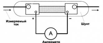
Measuring instruments and electrical equipment
On electrical measuring instruments you can see the same symbols as on electrical circuits. In this case, they say what kind of voltage or current the measuring device can operate with. For those devices that are designed to operate in a narrow area, symbols of the type of current or voltage can be located directly on the pointer (dial indicator). Universal measuring devices are equipped with a switch for the type and range of measurements, so all symbols are located near the corresponding positions.
Combined meter
Common digital testers have the following designations:
- ACA or ≈A – alternating current measurement mode;
- DCA or =A – direct current measurement mode;
- ACV or ≈V – alternating voltage measurement mode;
- DCV or =V – DC voltage measurement mode.
For electrical equipment, the type of power supply is indicated on a nameplate or tag. Devices with combined power supply have an alternating current sign on the tag in the form of a sine wave segment and one horizontal line.
Mixed current designation
English-speaking manufacturers use the abbreviation AC/DC to designate mixed or combined power supply.
Almost always, next to the voltage or current symbol, its value is indicated: separately for alternating current and separately for direct current.
Special symbols can be seen on the nameplate of AC motors. There, in addition to its type, the connection circuit (star or triangle) and the value of the supply voltage for each option are also indicated.
In addition, motors are characterized by power (current consumption) and the COSϕ value, which characterizes the reactive power of the consumer. This data is also present on the product tag.
Information on the meaning and type of power supply is important for the safety and proper functioning of the devices. To eliminate erroneous and unintentional activation of devices, mechanical protection is added to inappropriate power supplies, in addition to symbols. Thus, the power cord plugs of equipment using alternating current have a different pin shape than for direct current, which prevents the possibility of incorrect connection.
Kirchhoff's second rule
Kirchhoff's second rule applies to a closed loop in a circuit. A closed circuit is any sequence of connected elements within a branched electrical circuit such that the first and last elements are also connected.
The algebraic sum of the voltages when bypassing the circuit on the elements is equal to the algebraic sum of the EMF in the sources present in the circuit. If the direction of the EMF or voltage coincides with the direction of bypass, it is considered positive, if it does not coincide, it is considered negative: $U_1+U_2+... =mathscr{E}_1+mathscr{E}_2+...$.
Rice. 2. Kirchhoff's second rule.
This rule means that, firstly, the sources of the potential difference in the circuit are the sources of EMF, and secondly, when bypassing the circuit, the potential, while changing, still returns to its original value.
Application
Because DC only flows in one direction, its use is usually limited to low-energy-dense media, such as found in regular batteries, batteries for low-power appliances such as flashlights or phones, and batteries that use solar energy. But a constant source is needed not only for charging small batteries; high-power direct current is used to operate electrified railways, aluminum electrolysis or arc welding, as well as other industrial processes.
To generate direct current of such strength, special generators are used. It can also be obtained by converting an alternating variable; for this, a device is used that uses an electron tube, it is called a kenotron rectifier, and the process itself is referred to as rectification. A full-wave rectifier is also used for this. It, unlike a simple tube rectifier, contains electronic tubes that have two anodes - dual-anode kenotrons.
If you don’t know how to determine which pole direct current flows from, remember: it always flows from the “+” sign to the “-” sign. The first sources of direct current were special chemical elements, they are called galvanic. Later, people invented batteries.
AC is used almost everywhere, in everyday life, for the operation of household electrical appliances powered from a home outlet, in factories and factories, on construction sites and many other places. Electrification of railway tracks can also be done on DC voltage. So, the voltage goes through the contact wire, and the rails are the return electrical conductor. About half of all railways in our country and the CIS countries operate according to this principle. But, in addition to electric locomotives that operate only on constant and only alternating current, there are also electric locomotives that combine the ability to operate on both one type of electricity and another.
Alternating current is also used in medicine
For example, darsonvalization is a method of applying electricity at high voltage to the outer integument and mucous membranes of the body. Through this method, patients' blood supply improves, the tone of the venous vessels and metabolic processes of the body improves. Darsonvalization can be either local, in a specific area, or general. But local therapy is more often used.
Thus, we learned that there are two types of electric current: direct and alternating, otherwise they are called ac and dc, so if you say one of these abbreviations, you will definitely be understood. In addition, the designation of direct and alternating current in the diagrams looks like (—) and (~), which makes them easier to recognize. Now, when repairing electrical appliances, you will no doubt say that they use alternating voltage, and if you are asked what current is in the batteries, you will answer that it is constant.
Why is there a hold button in a multimeter and what is it for?
Data hold button , which the multimeter has, is considered useless by some, while others, on the contrary, use it often. It means data retention. If you press the hold button, the data displayed on the display will be fixed and will be displayed continuously. When pressed again, the multimeter will return to operating mode.
This function can be useful when, for example, you have a situation where you alternately use two devices. You have carried out some kind of standard measurement, displayed it on the screen, and continue to measure with another device, constantly checking with the standard. This button is not available on all models; it is intended for convenience.
Measuring direct and alternating current with a multimeter is also its main function, as is measuring resistance. You can often find the following designations on the device: V and V
- constant and alternating voltage, respectively. On some devices, constant voltage is designated DCV, and alternating voltage ACV.
Again, it is more convenient to measure current in automatic mode, when the device itself determines how many volts, but this function is available in more expensive models. In simple models, direct and alternating voltage during measurements must be measured with a switch depending on the range being measured. Read about this in detail below.