How to get a non-standard voltage that does not fit into the standard range?
Standard voltage is the voltage that is very commonly used in your electronic gadgets. This voltage is 1.5 Volts, 3 Volts, 5 Volts, 9 Volts, 12 Volts, 24 Volts, etc. For example, your antediluvian MP3 player contained one 1.5 Volt battery. The TV remote control already uses two 1.5 Volt batteries connected in series, which means 3 Volts. In the USB connector, the outermost contacts have a potential of 5 Volts. Probably everyone had a Dandy in their childhood? To power Dandy, it was necessary to supply it with a voltage of 9 volts. Well, 12 Volts are used in almost all cars. 24 Volt is already used mainly in industry. Also, for this, relatively speaking, standard series, various consumers of this voltage are “sharpened”: light bulbs, record players, amplifiers, etc.
But, alas, our world is not ideal. Sometimes you just really need to get a voltage that is not from the standard range. For example, 9.6 Volts. Well, neither this way nor that... Yes, the power supply helps us out here. But again, if you use a ready-made power supply, then you will have to carry it along with the electronic trinket. How to solve this issue? So, I will give you three options:
Power supply for screwdriver
All modern screwdrivers are battery operated. To ensure that it always remains charged, a power supply is required. Chargers from different manufacturers can vary significantly. Firstly, the blocks are equipped with different elements, and secondly, their voltage can be 12, 14 or 18 volts.
12 V chargers use transistors with a capacity of up to 4.4 pF, while the conductivity is at the level of 9 microns. To level the clock frequency indicators, capacitors are used. In chargers using this voltage, field-effect resistors are most often installed.
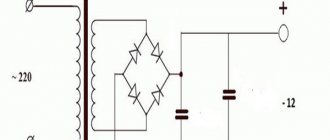
12V power supply circuit
The 14 V blocks already use 5 transistors and pulse capacitors. A four-channel type current conversion microcircuit is used. The resistor capacitance does not exceed 6.3 pF.
14V charger circuit
18 V chargers use only transition type transistors. A grid trigger is installed to normalize the maximum frequency. The current conductivity is in the region of 5.4 microns. There are 3 capacitors on the chip. A tetrode is located together with the diode bridge. Some models use chromatic resistors. Dipole transistors are sometimes used. 18V charger circuit
Batteries
Noticing that my parents had a pack of fresh round batteries, the idea of assembling a circuit immediately came to mind. It consisted of connecting batteries together. As a rule, regular batteries come with a voltage of 1.5 volts. And so, to get 12 volts, you had to take exactly 8 batteries. In general, it all looks like this:
Source rentps3.ru
Connecting the battery terminals requires a sequence: you need to connect the “+” of the previous element to the “-” of the next one. If everything is connected correctly, 12 volts will appear on the first and last terminals.
True, I doubted whether the assembled circuit would have enough power to recharge the screwdriver’s battery, so I put this method aside in case something more significant was not found.
DIY power supply for a screwdriver
The standard charger uses a three-channel chip. Depending on the voltage, a different number of transistors are placed on it, for example, 4 transistors are installed in a 12-volt charger. To reduce the negative effects of clock frequency, capacitors are installed in the blocks. They are of impulse or transient type. To minimize the consequences of electrical network overloads, thyristors are used in chargers.
Standard screwdriver charging circuit
This is important: in different models, not only different numbers of transistors are installed - they differ significantly in their capacity.
Power supply for a screwdriver from an energy-saving lamp In order to make a UPS from an energy-saving lamp, it is necessary to slightly change the electronic choke contained in each lamp by placing a jumper, and then connect it to a pulse transformer and rectifier. For low-power power supplies (from 3.7 V to 20 watts), you can do without a transformer. To do this, you simply need to add a few turns of semiconductor to the magnetic circuit of the inductor located in the lamp ballast, if there is room for this. The winding can be done directly over the factory one. To do this, it is better to use a wire with fluoroplastic insulation.
Power supply for screwdriver from charger
One of the cheapest ways to make a power bank is to use a regular smartphone charger. Every home now has two or more of them, and if you don’t have any extra, you can buy them for 50–100 rubles.
This is what the insides of a smartphone charger look like
The charging modification is carried out in the following sequence:
• Using a small diameter enamelled conductor, one turn of the winding must be added. After that, turn on the charger and connect the screwdriver to the battery. Using an oscilloscope, we measure the amplitude of the pulses and determine the voltage created by one turn of the additional winding. • Unsolder the USB connector, remove the test turn and wind the required number of turns until the required voltage is obtained. The new winding is soldered to the factory one in series. • We replace the standard capacitor and zener diode with new ones that correspond to the required voltage.
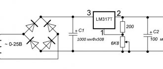
DIY switching power supply for a screwdriver
A suitable microcircuit is selected for the pulse unit, and assembly is carried out in the following sequence:
• Diode bridges and a thermistor are placed at the input. • Two capacitors are installed. • Drivers are used to synchronize the operation of the gates of field-effect transistors. • When installing transistors, the flanges are not short-circuited. They are attached to the radiator using insulating washers and gaskets. • Diodes are installed at the output.
Power supply for a screwdriver made from an electronic transformer
To adapt the transformer to the charger of your tool, it needs to be modified. To do this, you need to connect a capacitor at the output of the rectifier bridge. Capacitance is determined as follows - 1 µF per 1 W. The capacitor voltage must be at least 400 V. A thermistor must be installed in the gap of one network cable to limit the inrush current. A diode bridge is installed to rectify voltage with a frequency of 30 kHz. For normal operation of the device, a smooth start is required. Throttle L1 copes with this perfectly.
Setting up
To set it up, you should assemble the circuit on a breadboard; I strongly advise against assembling a working structure right away. Too large a spread in transformer parameters may require additional solutions.
First launch
For the first switching on, instead of the jumper “P”, an incandescent lamp 220V 100W is connected. Also, you need to connect a 20-30W lamp, a car lamp or a 12V halogen lamp to the output. Before starting, C15 is desoldered. A correctly assembled unit begins to work immediately: when turned on, the halogen light at the output glows (voltage about 14V), the protective lamp glows faintly. When turned on without a load, a faint squeak is heard in transformer Tr1 - these are attempts to start VS1. The protective lamp should not flash when turned on; without a load at the output of the unit, the lamp does not even smolder.
No-load operation
If everything matches what was described, we can continue; if not, we look for installation errors or faulty components. Next, you need to determine the need for OS voltage - you should connect a screwdriver to the output. When you turn on the shur, it should start, the protective lamp should flash. Perhaps the starting pulses will not be enough to start the screwdriver electronics. A voltmeter is connected to the output and the voltage is monitored; it should be in the working area. With a voltage of 2-3V, you should reduce the resistance of R8 so that a stable 13-15V appears at the output. Resistor R8 should not get warm, at most a little warm; for less heating, you can increase its power dissipation. If you manage to select a resistor and the shurik works without additional load, you don’t need a voltage feedback system and you won’t need C15 at all. When the unit is turned on and the screwdriver button is not pressed, a faint squeak is heard from the unit.
When operating on a halogen lamp, the transistors practically do not heat up; when operating without a load, there is no heating. The maximum that should heat up in the entire circuit is the snubber resistor R3, but this is not important for now.
If, nevertheless, the screwdriver does not start due to low initial voltage and selecting R8 did not give anything, within reason, without heating, you will have to do an OS by voltage. You should connect the circuit with C15, and turn on the unit without load. The output voltage should be 13-14V (with the specified secondary winding data). If the unit does not want to start, the C15 capacity should be increased. You should also try swapping the terminals of winding 3 of the power trance. As a result, you need to achieve a stable start without load with a minimum capacity of C15. When switched on, the protective lamp should not flash or even smolder. A disadvantage of the OS voltage may be a slight heating of the transistors at idle. You need to run the block for 5-10 minutes to determine whether the heating is acceptable.
An alternative for idle starting can be a choke from an energy-saving LDS, connected in parallel with the primary winding of the power transformer. This method is highly stable, but I have not tested it for heating.
The result of the adjustments should be a stable start of the unit (with OS, for example) or attempts to start with an output voltage sufficient to start the button electronics. At idle, nothing should get hot, or only slightly warm. An exception may be the snubber resistor R3, but this is the next step.
Screwdriver voltage
The winding data of the secondary winding 8+8 turns are designed for a 12V screwdriver. I can say with confidence that this winding is suitable for professional 14.4V models. I connected the unit to my working 14.4V screwdriver on a lithium battery, which easily screws 4X80 mm screws into raw wood without pre-drilling. Of course, I didn’t tighten such screws from the block, but I tore off the skin trying to stop the shaft.
If your voltage differs from 12V, then you should adjust the winding data of winding 2. When winding or unwinding the turns, you need to measure the voltage with a load - a 30W halogen lamp; without a load, the voltage will be slightly higher. I was guided by the supply voltage (12V) + 1V for drawdown (can be ignored). In general, if the screwdriver is 14.4V, you should not immediately wind extra turns; perhaps everything will work with the proper power without adding turns. I would also like to note 18V screwdrivers - despite the inscriptions on the case, they often have 12V motors. About power tests a little lower.
You also need to keep in mind that without a load the unit can develop a slightly higher voltage, so it would be a good idea to look for data shields for the button and the maximum voltage of its PWM. The most important thing is that the voltage at idle does not exceed this maximum. By the way, the voltage on the screwdriver battery without load is also slightly higher than the nominal voltage; for a 14.4V battery it is a little over 16 volts. However, due to the difficulty of selecting the winding voltage accurately, the unit may produce slightly more or less than the battery. In general, everything here is selected experimentally and with the head, and if you have assembled a prototype block, the head works.
Working start
Now you should remove the protective lamp and replace it with a jumper or 3-4A fuse. I'm not sure that the fuse is of any use, I installed it for peace of mind. Try starting with halogen at the output, idling - everything should be stable and without overheating.
Now you can connect the screwdriver and evaluate the rotation power. My green Bosch worked in such a way that probably with the new battery there was less power, but it did not overheat. To protect the screwdriver from too high currents, you can insert a limiting shunt into the open circuit, and at the same time measure the currents. I did not create protection on the field-effect transistor, and I don’t see any sense in it: the voltage drops in proportion to the increase in current, the current pulses when the button is pressed weakly are huge (albeit very short) and will force the protection to turn on.
It is necessary to check the capacitor accordion at the output for heating under heavy loads. I recorded the heaviest load at the moment of weakly pressing the button, when the engine beeps. In this case, the legs of a single capacitor were burned.
I couldn't stop the screwdriver with my hand! But I did get some decent calluses! Still, a limiting shunt will not interfere in the working unit; here you should be guided by the feeling of the rotational force, and not by measurements, and control the heating of the engine. I didn't put the shunt in the final version, it takes up too much space. Approximately, a shunt that limits a current of 20A is: 12V (in fact it will drop lower)/20A = 0.6 Ohm. Take a 0.6 Ohm shunt and, focusing on the rotation power, adjust it downwards until excessive heating appears.
Using a Chinese multimeter and a shunt, I measured the maximum current somewhere between 15 and 20A, this is when braking, as much as my strength and hands were enough. When the button was pressed weakly, when the engine beeped before starting, the currents were more than 20A. It is worth noting that the measurements are very approximate and may differ greatly from reality - a digital multimeter is not able to adequately measure the ripple voltage on the shunt. If you are a complete beginner and don’t know how to measure high current with a shunt and a multimeter, there will be a short review about this, but for now... Why do you need it?
Snubber
As I wrote above, the C5R3 chain can get very hot, or rather the resistor. And even if there is no heating at idle or low loads, at heavy loads the resistor can really stink. This is explained by an increase in the conversion frequency with an increase in the output current, therefore, the resistance of the capacitor decreases. Initially, C5 should be taken at 3.3 nanofarads (3300 pF) and selected according to the heating of the resistor, reducing the capacitance. I settled on 1000 pF. Please note that you should touch the parts with the unit turned off and capacitor C2 discharged. The rectified and filtered mains voltage is about 310V!
You should not reduce the capacitance of the capacitor by a margin so that there is no heating at all! Then it will be of little use. Heat should be tolerable for long-term use.
DIY screwdriver straightener
A rectifier is needed to convert AC to DC. It operates using semiconductor diodes, which act as converters. An oscilloscope is used to analyze the operation of the device. The main thing in the manufacture of a rectifier is the correct choice of diodes. For use in a power supply, elements with reverse current ratings of up to 10 amperes are suitable. The number of diodes is 4, and they should be installed as a bridge type. If the circuit is used on one semiconductor, the useful effect of the unit is halved.
This is important: it is prohibited to work with live electrical components. Before performing any manipulations, you need to make sure that the device is disconnected from the network.
Why remake a cordless screwdriver?
Why remake a screwdriver and when does the need arise?
If you are reading this article, you have probably already appreciated all the convenience of this tool. Without unnecessary wiring and at any time, you can use it even in the most inaccessible places, until the battery runs out. This is the first drawback of the screwdriver. The cheaper the tool, the faster its battery will exhaust its charging cycles.
Here is the second drawback. And you must understand that the manufacturer saves just as much as you do, and there is nothing unusual about it. Buying a new battery in terms of costs is practically no different from buying a screwdriver, but there is a way out, and now we will look at options for converting a screwdriver from battery to mains power.
There are several ways to convert a screwdriver from a cordless one to a mains one:
- using a laptop charger;
- using a PC power supply;
- using a car battery;
- using a power supply from halogen lamps;
- using a Chinese 24V power supply board.
Transformer block for powering a screwdriver
Transformer power supplies are devices that contain a transformer that reduces the input voltage. In addition to it, such blocks contain a diode rectifier and a filter capacitor. The capacitor smoothes out the output voltage ripple. In fact, the transformer produces the same type of voltage as in a 220-volt network, or rather, sinusoidal. When operating from uninterrupted sources, its shape may be completely non-sinusoidal. The shape of the rectified voltage is not constant over time, so it is necessary to install an element that maintains a constant output voltage, which is done on a smoothing capacitor.
Advantages of transformer blocks:
• Simplicity and reliability. • The components are easy to find commercially. • No parts that create radio wave interference.
Power supply for screwdriver
In order to power a screwdriver with your own hands from a household electrical outlet, you will need a failed battery, a battery charger, stranded wire, electrical tape, solder, a soldering iron and acid. First of all, you need to solder an electrical wire with a plug to the contacts of the charger. Since the block uses brass terminals and the wire has copper strands, in order to solder them, you must use acid as a connector. The functioning of the entire device directly depends on the quality of this connection. At the second stage, work is carried out with a failed tool battery. The battery should be disassembled and the internal parts removed. During this operation, you need to use personal protective equipment, and it is recommended not to throw the internal filling into household waste, but to dispose of it in a place safe for people. At the final stage, it is necessary to solder the charger wires to the battery terminals, which are located in the inside of the case.
When making a homemade power supply for a screwdriver, you must carefully observe safety precautions when working with electricity. Before starting work, you need to carefully weigh the pros and cons (how much time it will take, what the cost of materials and spare parts will be), sometimes it will be easier and cheaper to take the charger to a specialized workshop or purchase a new unit.
Conversion instructions
Let's take a closer look, step by step, at how you can convert a cordless screwdriver to a corded one.
Step 1: Disassemble the battery
In order to convert the instrument to a mains one, receiving voltage from the original charger or from the computer's power supply, you need to follow simple steps.
First, we disassemble the old battery. Unscrew the mounting screws. An important condition will be the preservation of all terminals.
Step 2: Pull out the insides
We take out the batteries and carefully release the terminals. Then a wire with a cross-section that can withstand the operating current is soldered to these terminals. The wire must be selected with a cross-section of at least 2.5 mm² and a length required for comfortable operation of the screwdriver. We remember what color wires we solder the negative and positive terminals to.
Step 3: Connect the wires
We disassemble the computer power supply housing. We take out the board and solder the wires on the power cable. To the wires coming out of the power supply, instead of the yellow and black wires, we solder the wires with the terminals from the battery. The black wire is the negative contact, the yellow wire is the positive contact.
You can increase the power that the power supply produces by connecting the black wire to black and yellow to yellow. This will improve the performance of the screwdriver because losses will be reduced.
To start the computer power supply, you need to short-circuit the green wire from the 20-pin connector to the black one. This can be done directly on the power supply board. For convenience, you can connect a switch to the green and free black wire.
For ease of use, you can solder a special connector to the wires, allowing them to be disconnected. Polarity must be observed, otherwise the screwdriver may be damaged. To do this, the connector must have a key (a special protrusion on the housing that prevents it from being connected incorrectly).
Step 4. Put everything back together and connect the screwdriver to a 220V network
It is necessary to assemble a “modified” battery. We insert the terminals with wires into it and bring them out through the drilled hole. It is recommended to place a capacitor with a capacity of 10,000 uF at 16 V or 25 V inside the body of the former battery and connect it to the terminals in parallel. You need to select a capacitor for a voltage that is 1.5 or 2 times the rated voltage of the tool.
Such a capacitor will compensate for the high starting current. If you do not install it, the likelihood of the power supply being turned off by the built-in protection will increase significantly. It is also recommended to place a weight inside to ensure the balance of the tool. This will reduce the strain on your hand while working.
Important! Before assembly, all wires must be properly secured to prevent them from being torn off.
We assemble the computer's power supply together and connect the screwdriver to a 220 V network. If, upon inspection, it turns out that the tool does not have enough power, you can replace the low-voltage power cord.