| Megaohmmeter in Wiktionary |
Megohmmeter
(from megaohm and
-meter
; outdated name -
megohmmeter
) is an electrical measuring instrument designed for measuring large resistance values. It differs from an ohmmeter in that when measuring resistance, a relatively high voltage is applied to the circuit being measured (in most models - 100, 500, 1000 or 2500 volts).
Megohmmeter is an outdated name for megohmmeter. In accordance with GOST 2.105, the use of colloquial speech, technicalisms, and arbitrary word formations is not allowed in documents.
In instruments of early designs, to obtain test high voltages, a built-in electromechanical constant voltage generator with a manual drive from a handle is usually used; the generator operates on the principle of a dynamo. Currently, megaohmmeters use an electronic inverter with a rectifier, powered from batteries built into the device or replaceable galvanic cells, as a source of constant high test voltage.
Pointer ratiometers were used as an indicator in megohmmeters of early designs.
Typically, a megohmmeter is used to measure the insulation resistance of high-voltage power cables.
The megohmmeter is also used to measure the high resistance of insulating materials (dielectrics) of wires and cables, electrical connectors, interwinding resistance of transformers, windings of electrical machines and other devices, as well as to measure the surface and volume resistance of insulating materials. Based on the measured resistances, the absorption (humidity) and polarization (insulation aging) coefficients are calculated.
About megohmmeters and megaohmmeters
Instead of a preface: Megger or megaohmmeter and measure For myself, I set the following gradation: Megger
- the brainchild of the Uman plant, region-DP and other switches, with a handle and an error of 15% (for example, ESki, Fki)
Megger
- originally an English electronic craft, with a small range measurements, for example up to 2-3 GOhm, test voltage is usually up to 1000 V - essentially a tester (Megger, Metrel, Sonel MPI-501, Chinese crafts)
Megohmmeter
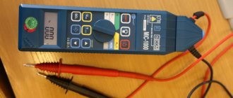
- a device that can measure tens and hundreds of gigaohms (that is, a meter at 2500V) and gives specific numbers.
(E6-24, PSI-2500, MIC-2500 series) Only a megohmmeter can detect poor insulation of a motor, transformer, cable when it still seems
to be working normally, but there is already a risk that it will “shoot” if this continues.
If the insulation resistance is more than 500 kOhm, you can turn it on without drying, but it is better to control drying with a megohmmeter. And the insulation value of a serviceable motor and cable can only be obtained by it. A very useful function that is sometimes necessary is the breakdown voltage and leakage voltage at 100 mA of the arrester, but this is not directly related to the measurement of insulation resistance. However, this is my personal “expert opinion”; according to the technical documentation, everything can be measured, and with verification, everything that is above the minimum is excellent... Although what is “excellent” if the cable insulation resistance is 2-3 MOhm?!
I had a broken ES0202/2-G 2002 lying around. They said that they had plugged it under voltage, but it turned out that the display meter was mechanically broken (the top extension was torn).
I bought a display meter and stretchers on Avito, it cost 690 with delivery by mail. I recommend! But they take a long time to travel (relatively - less than a week, the post office again worked better than SDEK), and my hands were itching... Therefore, I found from an ad for 500 rubles the same non-working ES, but from 1995 in Yubileiny, I went, picked it up and assembled one of the two. And then I looked through the ads and found E6-24 for 1000 (thousand!) rubles. According to the seller's description, it is fully functional, only without an adapter and converted to a lithium battery. Sent by SDEK from the Stavropol Territory on the 9th, arrived in Mytishchi on the 14th. However, Avito delivery takes the longest, so Russian Post rules...
Source
Megaohmmeter - purpose, how to choose
A megohmmeter is a device for measuring insulation integrity.
First of all, the device is capable of measuring large resistance values. Specifically, expressed in units of megohms, which gives it its name. But it should not be confused with an ohmmeter, which also measures resistance. However, it does not have its own high voltage source.
One of the most popular megaohmmeters today is the E6-24 model. The average price of E6 24 is in the range of 24,000 – 25,000 rubles. The measurement range is from 10 kOhm to 300 GOhm.
Features of using the device
- The device will produce high voltage that is dangerous to the lives of others. It is used with extreme caution.
- The circuits that will be tested should be de-energized before starting work.
- If measurements are taken in an apartment, then the circuit breakers located in the distribution panel are turned off. It is worth unplugging all appliances from the outlets.
- If you are checking the lighting circuit, you need to unscrew the light bulbs from all lighting fixtures.
You should work with megaohmmeters with extreme caution, observing safety precautions.
Source: evmaster.net
Megaohmmeter - purpose
The device is used to test the insulation resistance of electrical circuits. For this purpose, the device generates preset test voltages. Commonly used are 100, 500, 1000 and 2500 Volts.
By the way, previously the device was called a megometer, which did not fully reveal the essence of the device. Almost all modern models use a battery-powered voltage conversion circuit. The devices can take measurements in different periods of time (1-10 minutes or more).
Typically, a megohmmeter is used to measure the insulation resistance of cables. Although the device can measure the resistance of dielectrics of wires, transformers, connectors, windings, etc. Also used for measuring volumetric and surface resistances of insulating materials.
Based on the measurements, the polarization and absorption coefficients of the material are calculated. These indicators are of great importance in work. For example, while observing safety precautions for using electrical appliances. And also to prevent insulation breakdown, equipment failure, leakage or short circuit.
Effect of Induced Voltage
Electrical energy passing through power line wires creates a significant magnetic field. It changes in accordance with the sinusoidal law and contributes to the induction of secondary electromotive force and current I2 in metal conductors. In the case of a long cable length, the induced voltage reaches a significant value.
This factor has a significant impact on the accuracy of the measurements. The fact is that in this case the magnitude and direction of the electric current flowing through the measuring device is unknown. This current appears under the influence of the induced voltage and its value is added to the megohmmeter’s own readings obtained through the calibrated voltage of the generator. As a result, the sum of two unknown current quantities is formed, and this metrological problem becomes unsolvable. Therefore, measuring the insulation resistance of networks in the presence of any voltage is a completely pointless exercise.
Close attention to induced voltage is explained by the real possibility of electrical injury. Therefore, all employees must strictly adhere to established safety rules.
Megaohmmeter - how to choose?
Measuring insulation with a megohmmeter is a necessary procedure. For this reason, almost all industries should take care of purchasing a megohmmeter. Especially those who have a full-time electrician and use voltages over 500V for equipment.
Of course, you can buy any megaohmmeter in an online store. But before purchasing, it is better to familiarize yourself with several principles for choosing a device. When choosing, you should consider:
Insulating materials can have different resistances. However, there is a nominal resistance that certain insulating materials must meet. For example:
The device should be selected according to the specified parameters. As a rule, work with a megohmmeter should be carried out by a specialist. However, once a year the megohmmeter must be verified. In particular, to identify errors and the possibility of further operation of the device.
Source
Currently, on the market of measuring instruments, there are many different megohmmeters , or, as they are also called, insulation resistance meters. They all differ in their parameters, as well as in their price category. We have prepared this table for you to make choosing a megohmmeter a little easier. The table is compiled from the main technical characteristics. Let's look at each of them.
The test voltage generated by the device can vary from 50 to 10,000 volts. The only megohmmeter that covers the entire range of test voltages is MI 3200 . Other devices generate a certain voltage range.
The principle of generating test voltage : megohmmeters : - With a built-in mechanical generator
— Battery powered
-Battery power supply.
All types have both their pros and cons. Let's look at them:
Megaohmmeters with a built-in generator have a big advantage, such as operation at very low temperatures and for any amount of time, because voltage is generated manually. The disadvantage of this type of power supply is the accuracy of the measurement; rotating the generator handle at the same speed will make it difficult to maintain a stable voltage.
When using battery-powered megohmmeter, The disadvantage of this power supply is the constant need for batteries (AA batteries can be replaced) and poor performance at negative temperatures.
Battery power supply – high-capacity batteries supplied with the megohmmeter are used. One of the advantages is that it can work in autonomous mode for quite a long time; there is no need to constantly buy additional AA batteries. Cons: poor performance at sub-zero temperatures, need to be charged from an industrial network from time to time.
Measuring range of megohmmeters: The measuring range depends on the voltage. The higher the voltage that the megohmmeter , the greater the resistance the device can measure. Measurements range from 0 ohm to 10 tom.
Information output: There are two types of information output. Analog (A) and Digital (D).
Additional functions of the megohmmeter: There are several of them, but in our table we included only two functions - Measurement of absorption coefficient (DAR) and polymerization coefficient (PI), as well as communication with a PC
Megaohmmeter price: The price of the device depends on the parameters of the device itself. The higher the parameters, the higher the price.
order megaohmmeters by calling or sending us a request by email: This email address is being protected from spambots. Javascript must be enabled in your browser to view the address. You can also find out more about placing an order on our website.
Source
Manufacturer country
Almost a decade ago, it was believed that Chinese products should not be trusted. Low cost of products indicates poor quality. It is better to suspend your choice of European brands. There was a similar attitude towards producers from the CIS countries (the Commonwealth of Independent States is a regional international organization (international treaty) designed to regulate cooperative relations between states that were formerly part of the USSR)
.
At the moment everything has changed. When purchasing a product, we advise you to check with the manager where the assembly was carried out and where the parts were made. Almost all successful global brands have long employed Chinese employees due to the low cost of their work. In other words, the part can be made in Europe, but the device will be assembled in China. There is nothing disgusting about this; you can safely receive such products.
For almost all consumers, cost is the most important factor when choosing, but there is literally no point in saving. The operating time of your equipment may depend on the correctness of the measurements. There is no need to allow errors in electronics, as they can lead to disastrous results. The principle “The miser pays twice” literally works here. Therefore, it is better to choose a more expensive model.
Which megohmmeter is better to choose?
To protect people from electric shock when the insulation in consumer electrical installations is damaged, periodic monitoring of the insulation condition of electrical wiring, cables, electrical installations, etc. is necessary.
Insulation resistance and absorption coefficient are measured using a megohmmeter (megohmmeter).
A megohmmeter is a device that measures the direct current resistance of insulation. Until recently, the source of direct current was a generator with permanent magnets built into the megohmmeter, rotated by hand or by an electric drive. With the development of technology, digital megohmmeters began to be equipped with electronic converters, powered by an adapter or battery (for example, TsS0202, etc.), which led to a reduction in the size of the device.
Which megaohmmeter should you choose? The choice of megohmmeter type can be divided into several criteria.
APPLICATION
EASY TO USE
What type of display: pointer dial (ES0202, ES0210, M419, F4106), digital liquid crystal (TSS0202) or LED display, auxiliary devices: backlight, equipment (all megohmmeters from the Uman Megohmmeter plant).
OPERATING MODE
What are the climatic operating conditions (TSS0202-2 for the north)?
Should this device always be at hand?
Power source: magnetic-electric generator (available only in megohmmeters produced by the Uman Megohmmeter plant), rechargeable battery, battery?
What other measurements will need to be performed: current, voltage, absorption coefficient (TsS0202 measures)?
We recommend:
One of the main types of protection is the use of various types of insulation of live parts. The simplest, but very effective method of monitoring its condition is to measure the insulation resistance using a megohmmeter.
With this method of assessing the quality of insulation, the reliability of the readings comes to the fore, which consists of the basic error of the device, its resolution and additional error due to ambient temperature, humidity, etc., and for devices with dial indication also the parallax error vision.
Digital megohmmeters TsS0202-1 and TsS0202-2 developed and produced by Umansky measure the voltage at the facility, insulation resistance, and calculate the absorption coefficient. Megaohmmeters TsS0202-1 and TsS0202-2 automatically remember the last 10 values of RХ, R60 and R15, and also calculate the absorption coefficient.
All these parameters in the TsS0202-1 and TsS0202-2 megohmmeters can be displayed on the display by pressing one button. A wide operating temperature range (-30°C to +55°C) is achieved through the use of a vacuum-illuminescent display. All this will allow you to obtain reliable readings in almost any operating conditions.
The TsS0202-1 and TsS0202-2 devices are powered from a rechargeable battery, or from an alternating current network through an adapter, which also serves to charge the battery. Megohm meters TsS0202-1 and TsS0202-2 are equipped with a battery condition monitoring system. The built-in stabilizer protects the battery from overcharging. Also, the TsS0202-1 and TsS0202-2 megaohmmeters automatically switch to energy-saving mode 1 minute after the end of measurements (inactivity).
TsS0202 megohmmeters have better performance in most parameters compared to the E6-24 and E6-24/1 megohmmeters that appeared on the Russian market.
Comparative table of technical characteristics of TsS0202-2 and E6-24/1, E6-24:
Source
What is a megger? Operating principle of a megohmmeter
Devices used to directly measure insulation resistance are called ohmmeters. Depending on the measurement limits, they are usually called ohmmeters
, kiloohmmeters, meggers (meggers).
In Fig. Figure 1 shows a diagram of a portable megohmmeter. The resistance being measured is connected to terminals A and B. The moving system of the device is formed by two coils 1 and 2, mounted on the same axis and rigidly connected to each other at an angle of 90°. Coils 1 and 2 are placed in the field of a permanent magnet (not shown in the drawing). Coil 1 is connected in series with the measured resistance and has an internal resistance r0, coil 2 with additional resistance r is connected in parallel with the measured resistance.
The device is designed in such a way that when current flows, the torques arising in the coils are directed towards each other and the reading of the device depends only on the ratio of the currents in the coil, and not on the applied voltage. Consequently, the reading of the device does not depend on the speed of rotation of the device handle, which drives the rotor of the generator that powers the coils. This generator is built into the megger housing.
Megohmmeters
are manufactured in two types, which differ from each other in operating voltage and measurement limits: megohmmeters of the first type with an operating voltage of 500 V and with an upper measurement limit of up to 500 MΩ and of the second type with 1,000 V and 1,000 MΩ.
On marine vessels with DC installations, the insulation resistance of the live electrical network is usually measured using a special high-impedance voltmeter (the winding resistance of which is significantly higher than the winding resistance of a normal voltmeter). Using this voltmeter you can measure the voltage:
a) between the positive pole of the network and the hull of the ship Up; b) between the negative pole of the network and the ship’s hull Uо; c) between the positive and negative poles of the network, i.e. the voltage (U) operating in the ship's network.
These three voltmeter readings make it possible to determine the insulation resistance between each pole of the network and the ship's hull and the total insulation resistance between the network and the ship's hull.
in which r is the resistance of the voltmeter winding; hp is the resistance between the positive pole of the network and the ship’s hull; xo is the resistance between the negative pole of the network and the ship’s hull; x is the total insulation resistance between the network and the ship’s hull.
To facilitate calculations using these formulas, auxiliary tables are compiled and posted in the immediate vicinity of high-resistance voltmeters.
Compared to measuring insulation resistance with a megger, measuring with a high-impedance voltmeter gives less accurate results.
To measure the insulation resistance of ship's AC networks under voltage, a megohmmeter with an additional device is used, the circuit diagram of which is shown in Fig. 2.
Measuring device a is a magnetoelectric voltmeter with a scale graduated in ohms.
Additional device b consists of a step-down transformer
T; rectifier B; a smoothing filter (inductive coil L and capacitance C) and resistance R, from the terminals of which a direct current is taken, which is used to measure the insulation resistance of the network.
The DC circuit starts from the upper resistance terminal R (+). Through point 1 of phase C, the current enters the windings of generator G, where it branches out across all three phases of the network. Passing through the insulation resistance of all three phases (Riz) into the ship's hull, the direct current is again summed up into a total current going through the meter coil to the lower terminal of the resistance R of the additional device (—).
As you can see, the device shows the total insulation resistance of three phases without dividing the resistance into individual phases.
Source: www.electroengineer.ru
Design and principle of operation
The question of how to test a cable with a megohmmeter arises due to the impossibility of correctly measuring this indicator using a conventional multimeter. The latter does not make it possible to assess the presence of damage to the cable insulating layer and violations of its integrity: even in the case of a sufficiently high rated voltage, the leakage current is too small to be measured with a multimeter.
A megohmmeter makes it possible to determine the resistance of the insulating material separating cable cores, electric motor windings, and other structures in power tools.
Important! These devices are available in different versions. To choose which meter to purchase, you should rely on the features of their functioning, as well as take into account estimates and prices
Electromechanical megohmmeter
This is the earliest configuration of this device. It includes a current generator powered by rotating a handle, a resistance, an ammeter with a scale, as well as terminals to which the wiring is connected when determining the required parameters: grounding, line and screen. The apparatus can be described as having a simple design and not depending on external current sources. There are also a number of disadvantages: high scale error, the need to keep the instrument body motionless in order to obtain the most accurate measurements.
Electronic megohmmeter
In such devices, the test voltage is generated by an electrical circuit, and measurement is carried out using an analog type meter. This way you can check the resistance without having to turn the knob. It also allows you to measure the absorption index, which describes the moisture content of the insulating material.
Microprocessor megohmmeters
The main advantages of such devices are their compact design and the presence of a digital display. This allows you to combine different functions (assessment of grounding resistance, phase-neutral loop, and others) in one case, which eliminates the need to carry many devices with you.
User manual
The insulation resistance is checked on de-energized equipment or cable lines or electrical wiring. Remember that the device generates high voltage and if the safety precautions for using a megohmmeter are violated, electrical injuries are possible, because Measuring the insulation of a capacitor or long cable line can cause a dangerous charge to accumulate. Therefore, the test is carried out by a team of two people who have an understanding of the dangers of electric current and have received safety clearance. During testing of the object, no unauthorized persons should be nearby. Remember about high voltage.
Each time the device is used, it is inspected for integrity, for the absence of chips and damaged insulation on the measuring probes. Trial testing is carried out by testing with open and closed probes. If tests are carried out with a mechanical device, then it must be placed on a horizontal, flat surface so that there is no error in the measurements. When measuring insulation resistance with an old-style megohmmeter, you need to rotate the generator handle at a constant frequency, approximately 120-140 rpm.
If you measure resistance relative to the body or ground, two probes are used. When testing the cable cores relative to each other, you need to use the “E” terminal of the megohmmeter and the cable screen to compensate for leakage currents.
Insulation resistance does not have a constant value and largely depends on external factors, so it can vary during measurement. The check is carried out for at least 60 seconds, starting from 15 seconds the readings are recorded.
For household networks, tests are carried out with a voltage of 500 volts. Industrial networks and devices are tested with voltages in the range of 1000-2000 volts. You need to find out exactly what measurement limit to use in the operating instructions. The minimum permissible resistance value for networks up to 1000 volts is 0.5 MOhm. For industrial devices, no less than 1 MOhm.
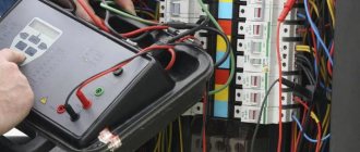
As for the measurement technology itself, you need to use a megohmmeter according to the method described below. As an example, we took the situation with measuring insulation in a switchboard (power panel). So, the procedure is as follows:
We remove people from the part of the electrical installation being tested. We warn about the danger and post warning posters. We remove the voltage, completely de-energize the shield and input cable, and take measures against erroneous voltage supply. We hang up a poster - DO NOT TURN ON, PEOPLE ARE WORKING. We check that there is no voltage. Having previously grounded the terminals of the test object, we install the measuring probes, as shown in the megohmmeter connection diagram, and also remove the grounding. This procedure is carried out with each new measurement, since nearby elements can accumulate a charge, introduce an error in the readings and pose a danger to life. Installation and removal of probes is carried out using insulated handles while wearing rubber gloves.
Please note that the insulating layer of the cable must be cleaned of dust and dirt before checking the resistance.
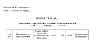
We check the insulation of the input cable between phases A-B, B-C, C-A, A-PEN, B-PEN, C-PEN. The results are recorded in the measurement protocol
We turn off all automatic devices, RCDs, turn off lamps and lighting fixtures, disconnect the neutral wires from the neutral terminal. We measure each line between phase and N, phase and PE, N and PE. The results are entered into the measurement protocol. If a defect is detected, we disassemble the measured part into its component elements, look for the fault and fix it.
At the end of the test, we use portable grounding to remove the residual charge from the object, by short-circuiting, and from the measuring device itself, discharging the probes among themselves. According to these instructions, you need to use a megohmmeter when measuring the insulation resistance of cable and other lines. To make the information more clear to you, below we have provided videos that clearly demonstrate the order of measurements when working with certain models of devices.
Danger of overvoltage of the device
When working with a megohmmeter, there are specific features that you should pay close attention to. This is primarily due to the increased voltage of the device. The built-in generator has an output power sufficient not only to test insulation, but also to cause serious electrical injury. Therefore, in accordance with electrical safety rules, only trained and qualified specialists with at least 3rd tolerance group can use a megohmmeter.
During the measurement process, increased voltage covers the area being tested, as well as the terminals and connecting wires. Protection against this is provided by probes having a reinforced insulated surface. They are designed for installation on test leads. The ends of the probes are limited to a restricted area using safety rings. This prevents exposed parts of the body from touching them.
Read also: Fastening the corrugation in the groove
To perform measurements on the measuring probes, a special working area is provided, which you can safely handle with your hands. Direct connection to the circuit is made using alligator clips with good insulation. The use of other types of wires and probes is prohibited. When performing measurement work, there should be no people in the entire area being tested. This issue is especially relevant in cases where the insulation resistance is measured in long cables, up to several kilometers long.
SAFETY INSTRUCTIONS FOR WORKING WITH A MEGGER.
At numerous requests from our customers, we have developed and published “Safety Instructions for Working with a Megger.” We believe that such instructions, or similar ones, should be in every enterprise that uses a megohmmeter in their work.
1. General safety requirements.
1.1. All work that is carried out using a megohmmeter in existing electrical installations must be carried out according to an order or order drawn up in writing. 1.2 To carry out work on measuring insulation resistance with a megohmmeter in existing electrical installations above 1000 V, it must be carried out by at least two workers: one with group IV, the other with group III .Measurement of insulation resistance with a megohmmeter in electrical installations up to 1000 V and in inactive electrical installations is allowed to be carried out by one worker with group III.
1.3. Conductors used to connect the megger to live parts must be certified and have appropriate insulation and insulating holders to ensure the safety of measurements.
1.4. When measuring insulation resistance, the megger must be installed on a solid insulated support. 1.5 The worker carrying out measurements with the megger must know the safety instructions and operating instructions for the device.
1.6. It is prohibited to take measurements with a megger: 1.6.1. if one of the circuits of double-circuit lines has a voltage above 1000 V, if the second circuit is energized;
1.6.2. on a single-circuit line, if it runs in parallel with a working line with a voltage above 1000 V; 1.6.3. during a thunderstorm or as it approaches.
2.Safety requirements before starting work.
2.2. If necessary, remove the charge from live parts by first grounding them.
2.3.Connect the megohmmeter to live parts using connecting wires with insulating holders. In electrical installations above 1000 V, in addition, it is necessary to use dielectric gloves or mats.
2.4 Before starting measurements, make sure that there are no people working on that part of the electrical installation to which the megohmmeter is connected, and also prohibit those nearby from touching live parts, and if necessary, set up security.
3.Safety requirements when taking measurements with a megger.
3.1.When working with a megger, you must follow the operating instructions for the megger and strictly follow the sequence of actions when taking measurements.
3.2. It is prohibited to touch the megger terminals and live parts to which it is connected.
3.3. The use of non-certified conductors and clamps used when taking measurements with a megger is prohibited.
3.4. After carrying out measurements with a megger, it is necessary to remove the residual charge from current-carrying parts by briefly grounding them. The worker grounding live parts must wear dielectric gloves, safety glasses and stand on an insulating base.
When putting a cable into operation, during and after repair work, in case of problems with wiring - in all these cases it is necessary to check the condition of the cable insulation. A regular multimeter can only indicate that there is a problem. And its specific scale can only be determined using a special device - a multimeter. This device is classified as professional, but modern devices can have several functions (measurement of other parameters of electrical networks). So some owners of houses, cottages, and garages prefer to have their own. How to take measurements, how to use a megohmmeter, and we’ll talk further.
The mechanism of operation of an electromechanical megohmmeter
The task of any megohmmeter is to draw the voltage of the value chosen for measurement at the measuring terminals and measure the current passing through the measured circuit.
At first, constant current electromechanical machines were used to generate voltage. Their rotors were rotated using the handle of a megohmmeter. In order for the generator to produce the rated voltage during measurements, the rotation frequency was kept within 2 revolutions per second .
Megaohmmeter M4100
M4100 megohmmeters , but are also used at the moment - in ESO 202 . The advantage of these devices is one: they do not require a network connection, nor batteries or batteries. But there are many more shortcomings:
- It is difficult to keep the device body motionless during measurements . Together with the body, the needle also twitches, which reduces the accuracy of measurements.
- The device readings depend on the rotation speed .
- In places where the device wires have to be held with your hands during measurements (using dielectric gloves, of course), two people are involved in the measurements . One ensures contact of the wires with the measurement object, the other turns the megohmmeter handle.
- With a larger number of measurements required, the process is slower than when using electrical devices.
The measuring system of electromechanical devices is analog, the results are read on a scale with a pointer indicator . An additional drawback of the measuring system is that the scale is nonlinear and the accuracy class is small .
Megaohmmeter ESO 202
The difference between the modern ESO 202 device and the M4100 is the presence of a switch for voltages output by a megohmmeter. This is convenient when taking measurements on objects that contain electrical equipment, the insulation resistance of which is determined at various voltages. For example, cables with a voltage of 380 V (insulation measured at 1000 V) and electric motors (500 V). Otherwise, the devices are identical, only the switching of measurement ranges for the M4100 is done at the terminals of the device, and for the ESO 202 - with a switch.
How to connect a megohmmeter?
For each model of devices for this purpose, the output voltage value is determined, so in order to effectively test the insulation or measure its resistance, you need to choose the right megohmmeter.
Watch this video on YouTube
To check the cable insulation with a megohmmeter, a so-called extreme case is created, in which a voltage higher than the rated one is applied to the test section, but within the permissible standards specified in the technical documentation.
For example: a megohmmeter generator can produce:
Accordingly, the voltage supply should be an order of magnitude greater.
The duration of the measurement process usually does not exceed 30 seconds or minutes; this is necessary for more accurate detection of defects, as well as to eliminate their subsequent appearance during voltage surges in the network.
The basis of the technological process of measuring resistance is: preparation for the process, its implementation and the final stage. Each of them includes a certain list of manipulations necessary to achieve the goal without harm to others and, first of all, to oneself.
When preparing for work, you should organize your actions, study the electrical installation diagram to eliminate possible breakdowns, and also ensure your safety.
When starting work, you should first check the device for serviceability. To do this, the leads are connected to the measuring leads. Then their ends are connected to each other in an attempt to short-circuit. After applying voltage, the measurement readings are taken (they should be equal to zero). The next stage involves re-measuring. If there are no malfunctions, the reading should differ from the previous one.
Then they connect the portable grounding to the earth circuit, check and ensure that there is no voltage in the area, install the portable grounding, assemble the measuring circuit of the device, remove the portable voltage, remove the residual charge, disconnect the connecting wire, remove the portable voltage.
The final stage involves restoring the disassembled circuits, removing shunts and short circuits, as well as preparing the circuit for operating mode. The obtained results of measuring the resistance of the insulating layer are documented in the insulation verification report.
Effect of residual charge
A working megohmmeter generator produces voltage, so the earth circuit forms different potential values, thanks to which a semblance of a capacitance is created that has a certain charge. After measurements are taken, some part of the capacitive charge remains in the wire. As soon as a person touches this area, electrical injury is guaranteed, so the constant use of additional safety measures will not be superfluous, namely:
- portable grounding;
- insulated handle;
- Before connecting the device to the circuit under test, you should check the presence of voltage in it, as well as the residual charge using a voltmeter.
Where is it used?
Insulation, like any material, deteriorates and wears out over time and due to weather conditions. To promptly detect an insulation defect, a megohmmeter is used. It is needed to measure the insulation resistance of a power cable, electrical connector, transformer interwinding, or electrical machine. It is also necessary to measure surface and bulk dielectrics. The advantage of the device is complete autonomy, independence from power sources and automatic calculation of the absorption and resistor processes.
Application in industrial conditions as the main area
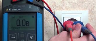
Insulation resistance: how to measure correctly
Before measuring resistance, you need to carefully study the electrical installation diagram, prepare protective equipment and the device itself is in good condition. The area being tested must be taken out of operation in advance.
Checking the serviceability of the megohmmeter is as follows. The test leads are shorted together. After this, voltage is supplied to them from the generator. If the device is working properly, the measurement results of the shorted circuit are zero. Next, the ends of the wires are disconnected, moved to the sides, after which a repeat measurement is made. Normally, the scale displays an infinity symbol, indicating the insulation resistance in the air gap between the measuring ends.
Direct measurement of insulation resistance is performed in a strictly defined sequence. First of all, the portable ground must be connected to the circuit. There should be no voltage in the area being tested. Next, the measuring circuit of the device is assembled, and the portable grounding is removed.
A calibrated voltage is applied to the circuit until the capacitive charge is equalized. Next, the countdown is recorded, after which the voltage is removed. To remove the residual charge, a portable grounding is applied. At the end of the measurements, the connecting wire is disconnected from the circuit, and the grounding is removed.
To measure insulation resistance with a megohmmeter, the highest MΩ limit is used. If this value is not enough, you need to use a more accurate range. All further chains of measurements must be performed in the same sequence. Some megaohmmeter designs can operate in intermittent mode. In this case, voltage is applied for one minute, after which there is a pause for two minutes.
If there is a dial indicator in the measuring instruments, the horizontal orientation of the body is used for all measurements. Violation of this requirement leads to additional errors. Modern digital megohmmeters can operate in any position.
Measuring insulation resistance with a megohmmeter
How to use a multimeter step by step instructions
How to use a voltmeter
How to use a multimeter
Measuring the insulation resistance of electrical wiring
How to use a megger
Where will you work (operating conditions)
We are talking about the temperature regime and the location of the measurements: indoors or outdoors. If the insulation resistance measurement will take place in the cool season outside of a warm room, then it is not permissible to obtain a model with a digital display. It is simply not designed for such conditions.
Choose non-volatile models with analogue display. They can be battery-powered or have an integrated mechanical generator. By the way, analogue options are noticeably more expensive, and they differ in the highest accuracy.
Device and principle of operation
A megohmmeter is a device for checking insulation resistance. There are two types of devices - electronic and pointer. Regardless of the type, any megohmmeter consists of:
Probes, through which voltage from the device is transmitted to the object being measured.
In pointer instruments, the voltage is generated by a dynamo built into the housing. It is driven by a meter - it rotates the handle of the device with a certain frequency (2 revolutions per second). Electronic models take power from the mains, but can also run on batteries.
The operation of the megohmmeter is based on Ohm's law: I=U/R. The device measures the current that flows between two connected objects (two cable cores, core-ground, etc.). Measurements are made with a calibrated voltage, the value of which is known; knowing the current and voltage, you can find the resistance: R=U/I, which is what the device does.
Approximate diagram of a magaohmmeter
Before testing, the probes are installed in the appropriate sockets on the device, and then connected to the object being measured. During testing, a high voltage is generated in the device, which is transmitted to the object being tested using probes. Measurement results are displayed in mega ohms (MΩ) on a scale or screen.
Measurements with a megohmmeter
When starting to check the cable insulation with a megohmmeter, you need to determine what type of wire you are testing. The description of the sequence of work for different types of cables is similar, but for each group there are certain nuances.
Measuring high voltage lines
This includes wires with voltages of more than a thousand volts. According to standards, the insulation of such products must have a resistance exceeding 1000 MOhm. The device used for measurements must be designed for 2500 V (similarly for low-voltage cables).
Testing of low voltage cables
For such cables, the indicator should be at least 0.5 MOhm. First, the device is placed between the phase conductors, then - between the phases and zero, after that (if the wire has five conductors) - between the phases and grounding, at the very end - between the grounding and neutral conductors (the latter must be disconnected from the bus before this).
Testing of control cable systems
Devices of 500-2500 V are used here. The final result should be more than 1 MOhm. The output of the device is placed on one core, the remaining ones are connected and placed on the ground. The second output is placed on any core that is not subject to measurement at the moment. Having made the measurements, the vein is placed with the others and the next one begins to be tested.
Preparing for work
Before you check the resistance of any cable, you must make sure that there is no voltage on it. For high-voltage lines, a high-voltage indicator is used, for low-voltage lines, protective means are used for manipulations in electrical installations. Warning posters must also be posted.
Line connection
The standard package includes three probes with different characteristics and structures. One of them has two tips and is designed to combat leakage currents. On the top side of the device there are three sockets for connecting probes. Each of them is characterized by a corresponding letter marking:
- Z - for connecting protection grounding.
- L is the line that is being measured.
- E - screen (intended to eliminate leakage currents).
You may be interested in this Mathematical notation of the Joule-Lenz law and its application
There are no other options, except for cases with shielded wiring. However, in private buildings such methods are not used, since the installation of cables with a screen is practically useless here. However, if you have this type of cable, you need to minimize the risk of leakage currents by using a probe with a split end. The wires of the shielding braid must be twisted into a bundle, adding to the general bundle of wires.
Measuring cable insulation resistance with a megohmmeter
The procedure is as follows (CABLE DE-energized):
If we have a three-core cable, then we must obtain the phase-to-zero and phase-to-phase insulation resistance values. Total 6 measurements. In reality, they do not make three measurements, but one - they combine three wires and apply voltage from the megohmmeter to them. If the insulation resistance value is satisfactory, then everything is fine. If Rx is unsatisfactory, then each core is measured separately.
Record readings at 15 and 60 seconds to determine the absorption coefficient (Ka). This coefficient is numerically equal to the ratio of resistance values R60/R15. Shows the degree of moisture. There is also the concept of polarization coefficient or polarization index (PI) - it is equal to the ratio R600/R60 and characterizes the degree of aging of the insulation. The standards define the following values:
The limit value indicates that the cable is unsuitable for use. The polarization index is measured on cables with impregnated paper insulation along with Ka. For cables with plastic, PVC, or cross-linked polyethylene insulation, there is no need to determine the polarization index.
Now there are various digital and electronic megohmmeters. In digital ones you can immediately see after measuring the values of the absorption coefficient, R60, R15; separate devices allow you to measure PI. In addition, for sonel models you can press the start button, then use another button to lock it and not hold your finger on the button for a minute. The devices operate on batteries. It makes life easier.
In pointer instruments, the source of constant voltage (and tests with a megohmmeter are tests with constant voltage) is based on either a generator or a button (ESO models).
Here you will either have to turn the handle of the device at a speed of 2 rps, or look for an outlet. And besides this, you still need to count down the stopwatch and record the results. The scales of individual instruments also cause difficulties. But megaohmmeters from various manufacturers are the topic of a separate large article.
In general, do not forget to discharge the cable after testing, removing the accumulated charge by grounding. And only then remove the end of the device from the core being tested. And the longer the cable, the longer you keep it grounded.
Cable insulation resistance measurement
The insulation resistance of electrical wiring is measured at two points in the electrical installation, which characterize leakage when voltage is applied to the network. The result is an indicator expressed in megaohms. The measurement is carried out using a megohmmeter, which examines the current leakage that occurs when regularly supplied voltage to an electrical installation.
Modern megohmmeters provide different voltage levels to test different equipment. As a result, a mandatory part of testing a circuit is studying the insulation resistance.
The principle of measuring the indicator
Types of testers
When operating electrical devices, digital megohmmeters of the model: F4101/4102 from 100.0 to 1000.0 V are widely used. Installers still work with tester brands M4100/1, 4100/5 and MS-05 m from 100.0 to 2500.0 V. The choice of megger size is based on rated resistance of the device under test: power cables and transformers, machines and insulators. To determine the state of insulation in electrical installations up to 1000.0 V, it is allowed to use megohmmeters from 100.0-1000.0 V, and in installations over 1000.0 V - 1000.0-2500.0 V.
Devices are also classified by the voltage generated and resistance limits in megohms:
Additional Information. The devices also differ in accuracy classes. The popular M4100 model has an error of no more than 1%, and the F4101 brand has an error of up to 2.5%. The selection of electrical installation testing devices is carried out taking into account acceptable performance indicators.
Electronic meter
Electronic meter
A digital or electronic tester is a modern type of equipment, equipped with a powerful generator with field-effect transistors. Measurements are made by comparing the voltage drop in a reference circuit with a fixed resistance. The results are shown on the panel. The test results saving function accumulates data for subsequent analysis. This model differs from analog devices in its compact size and light weight. Advantages of a digital tester:
Disadvantages of the electronic type megger:
Electromechanical meter